DELTA DORE DRIVER 620, DRIVER 610 Installation Guide
- Installation manual (4 pages) ,
- User manual (2 pages)
Advertisement
Introduction
- Carefully read these instructions prior to installation.
- The unit must be installed in compliance with current standards.
- Always switch off the mains before installing or servicing the unit.
- Do not attempt to repair the unit yourself; an after-sales service is available.
- Check that the fastenings are suited to the surface to which the unit will be attached (plasterboard, brick, etc.).
- The diagrams provided are simplified for greater clarity. Protections and other accessories required by standards are not illustrated. Standard NF C15-100 and good practice must be complied with. Connected or nearby units must not generate excessive interference (directive 2004/108/EC).
Because of changes in standards and equipment, the characteristics given in the text and the illustrations of this document are not binding unless confirmed by our services.
Technical characteristics
- 230 V, 50 Hz power supply, ±10%
- Consumption: 2 VA
- Class II insulation
- 1 or 2 pilot wires output 0.1A / 230V
- Clock backup in the event of a blackout: 2 hours (per capacitor)
- Dimensions: WxHxD = 80 x 103 x 16 mm
- Protection index: IP 30
- Installation in an environment with normal pollution levels
- Storage temperature: -10°C to +70°C
- Operating temperature: 0°C to +40°C
Room unit mounting

The room unit must be installed at a height of approximately 1.5 m, so that it is within arm's reach for ease of use. To attach the unit to the wall, you must separate it from its base. To do so, unlock the casing.

Unscrew the terminal box cover and lift it up as high as it will go to block it, then position the base on the wall running the wires out through the hole in the cover. Secure the base using suitable screws and screw anchors or fit onto a flush-mounted box (distance between centres 60 mm).
Connect the control wires. Close the box and tighten the terminal box cover screw.
Connection
 Put all of the installation's convectors on Comfort (with the set-point on its maximum setting). When the unit is switched on, a test lasting about 1 minute 30 seconds checks that the outputs are correctly connected. If the display remains "normal", this means there are no problems. If a problem exists, the DRIVER displays Pb - -.
Checking the pilot wire connections

Put all of the installation's convectors on Comfort (with the set-point on its maximum setting).
When the unit is switched on, a test lasting about 1 minute 30 seconds checks that the outputs are correctly connected.
If the display remains "normal", this means there are no problems.
If a problem exists, the DRIVER displays Pb - -.
Output 2 test underway.

Repeat the operations for zone 1.
Check the incorrect connections.
To exit test mode, press the init button.
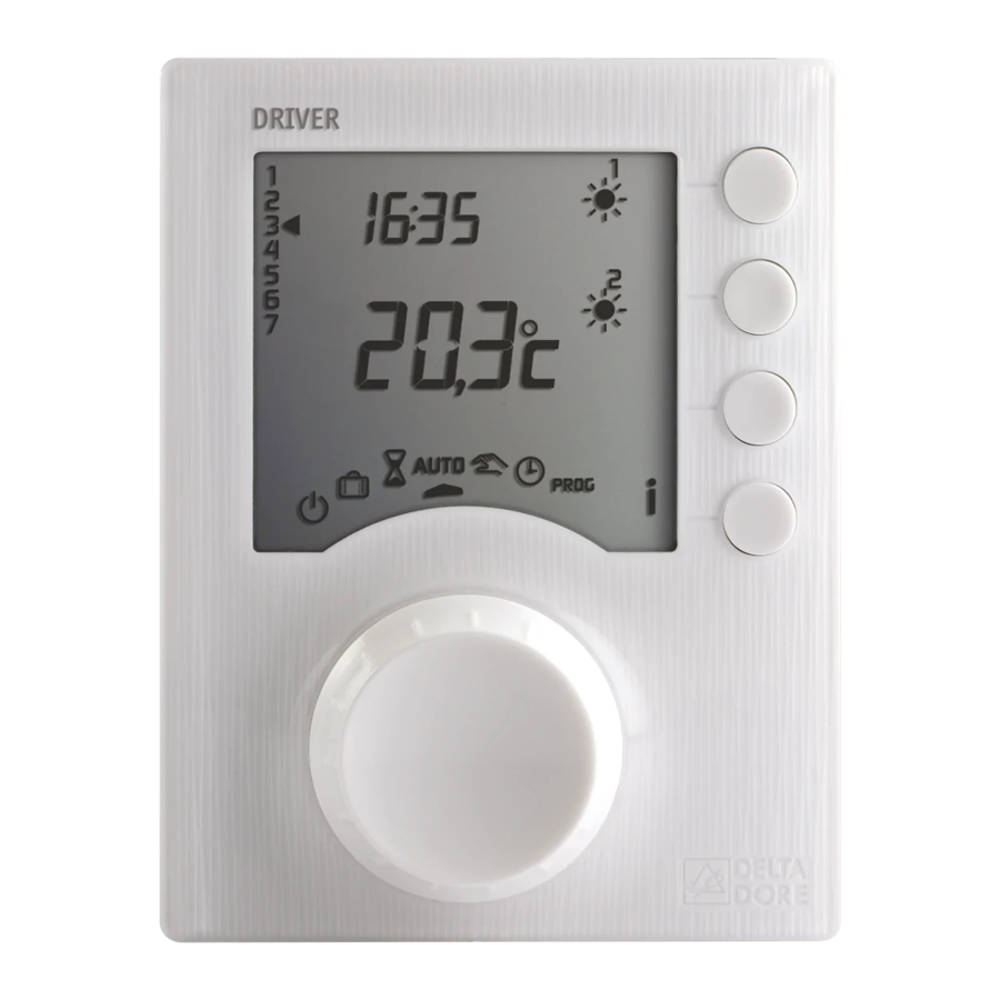
Time setting

The first time you activate the unit, you must set the clock. Turn the selector dial to  The days flash.
Press + or - to set the day, then OK to confirm and go to the next setting. Repeat these steps for the other menus. To exit the "time setting" mode, turn the selector selector dial.
Basic configurations (menu 1)

To enter the configuration menus, turn the selector dial to  , then press and hold the i button for 5 seconds. The unit will propose 2 configurations to choose.
After each menu has been configured, the unit returns to the choice of menus.
Advanced configurations (menu 2)
")
If there is a difference between the actual temperature (taken with a thermometer) and the temperature measured and displayed by the unit, function 2-02 can be used to compensate for the difference by changing the way the sensor takes measurements.
Example : If the temperature displayed by the unit is 19°C and the temperature measured is 20°C, add 1°C to the display and confirm by pressing OK.
Reset

The factory settings may be restored for each of the menus.
Turn the selector dial to ![]() , then press and hold the i button for 5 seconds.
, then press and hold the i button for 5 seconds.
Repeat these steps for the other menus.
To exit the mode, turn the knob to another mode.
Troubleshooting
Nothing is displayed on the room unit screen.
There is no power supply.
Check the circuit breaker.
Pb — is displayed on the screen.
Problem with the connection on a Pilot Wire output.
Contact our technical department.
The i symbol flashes.
A fault is detected on the installation.
Press the button to view the fault(s).
The device displays: dEF and a number
There is a fault with the unit which requires a return to our after-sales service.
Contact our technical department.


Documents / Resources
References
Download manual
Here you can download full pdf version of manual, it may contain additional safety instructions, warranty information, FCC rules, etc.
Download DELTA DORE DRIVER 620, DRIVER 610 Installation Guide
Advertisement


Need help?
Do you have a question about the DRIVER 620 and is the answer not in the manual?
Questions and answers