Table of Contents
Advertisement
Quick Links
Installation guide
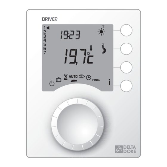
DRIVER
Pilot wire programmer
DRIVER 610 - 1 projecting zone
DRIVER 620 - 2 projecting zones
DRIVER
DELTA DORE
Bonnemain - 35270 COMBOURG - France
E-mail : deltadore@deltadore.com
Unit compliant with the requirements of directives:
2004/108/EC (Electromagnetic Compatibility)
and 2006/95/EC (Low-Voltage Safety)
Because of changes in standards and equipment, the characteristics
given in the text and the illustrations in this document are not binding
unless confirmed by our services.
Warning
• Carefully read these instructions prior to
installation.
• The unit must be installed in compliance with cur-
rent standards.
• Always switch off the mains before installing or ser-
vicing the unit.
• Do not attempt to repair the unit yourself; an after-
sales service is available.
• Check that the fastenings are suited to
the surface to which the unit will be attached (plas-
terboard, brick, etc.).
• The diagrams provided are simplified for greater cla-
rity. Protections and other accessories required by
standards are not illustrated.
Standard UTE NF C15-100 and good practice must
be complied with. Connected or nearby units must
not generate excessive interference (directive
2004/108/EC).
Checking the pilot wire connections
Put all of the installation's convectors on Comfort (with
the set-point on its maximum setting).
When the unit is switched on, a test lasting about 1
minute 30 seconds checks that the outputs are cor-
rectly connected.
If the display remains "normal", this means there are
no problems.
If a problem exists, the DRIVER displays Pb - - .
Exit and relaunch
text mode
Launch the test
output by output
Choose the output to test
Approve and restart the test
for the chosen output
Example: test for output 2
Room unit mounting.
The room unit must be installed at a height of approxi-
mately 1.5 m, so that it is within arm's reach for ease
of use.
To attach the unit to
the wall, you must
separate it from its
base. To do so,
unlock the casing.
Unscrew the terminal box cover
and lift it up as high as it will go to block it, then position
the base on the wall
running the wires out through
the hole in the cover.
Secure the base using suitable
screws and screw anchors or fit
onto a flush-mounted box
(distance between centres 60
mm).
Connect the control wires.
Close the box and tighten the
terminal box cover screw.
Output 2 test underway.
OR
The output's number
The output's
becomes fixed
number disappears
Connection of output
Connection of output
2 incorrect
2 correct
Repeat the operations for zone 1.
Check the incorrect connections.
To exit test mode, press the
init button.
Connection
DRIVER 610
DRIVER 620
Convectors
Convectors
terminal 3
zone 1
zone 1
Convectors
terminal 4
NC
zone 2
DRIVER 610
DRIVER 620
Zone 2
Pilot Wire
Convectors
N
L
NC
N
L
Zone 1
Pilot Wire
Convectors
Zone 1
Pilot Wire
Convectors
Activation
The first time you activate the unit, you must set
the clock.
Minutes
Days
(1: Monday ...
7: Sunday)
Hours
Turn the knob to
.
The days flash.
Press + or - to set the day, then OK to confirm and go
to the next setting.
Repeat these steps for the other menus.
To exit the "time setting" mode, turn the selector knob.
Advertisement
Table of Contents

Subscribe to Our Youtube Channel
Related Manuals for DELTA DORE DRIVER 610


Summary of Contents for DELTA DORE DRIVER 610
-
Page 1: Installation Guide
Convectors terminal 4 rent standards. zone 2 separate it from its DRIVER 610 - 1 projecting zone base. To do so, • Always switch off the mains before installing or ser- DRIVER 620 - 2 projecting zones unlock the casing. - Page 2 Configuration Basic configurations (menu 1) Advanced configurations (menu 2) To enter the configura- Press button Press button Correction possible from -5°C to + 5°C tion menus: in increments of 0.1°C. - Turn the knob to Correcting Press the + or – buttons to modify, the temperature then press and hold and press the OK button to confirm.
-
Page 3: User Guide
This unit is used to program the Comfort or Economy Pilot Wire Room VER 611 or 621. mode of the heating for 1 zone (DRIVER 610 or 611) or Setting on the heat emitter order temperature 2 zones (DRIVER 620 or 621),... - Page 4 Programming Example: Comfort from 6:00 to 8:00 and from 17:00 to 23:00 Check your program Turn the knob to PROG 00:00 6:00 8:00 17:00 23:00 00:00 The default program is a Comfort period from 6:00 to Press the button repeatedly to check the accuracy 23:00.
Need help?
Do you have a question about the DRIVER 610 and is the answer not in the manual?
Questions and answers