Table of Contents
Advertisement
Quick Links
Advertisement
Table of Contents

Subscribe to Our Youtube Channel
Related Manuals for SVS-Vistek HR Series


Summary of Contents for SVS-Vistek HR Series
- Page 1 Manual HR series hr16050, hr16070, hr25, hr29050, hr49, hr65, hr120...
-
Page 2: Table Of Contents
Content Company information Standards Disclaimer Copyright notice Legal information USA and Canada Europe The HR camera series Focusing on details Camera Link features 4I/O adds light and functionality Getting started Contents of camera set Connect the camera Camera status LED codes Software 4.4.1 SVCapture 2... - Page 3 6.1.1 Global shutter 6.1.2 Rolling shutter 6.1.3 Exposure 6.1.4 Exposure speed 6.1.5 Acquisition and processing time 6.1.6 Auto exposure 6.1.7 Bit depth 6.1.8 Gain 6.1.9 Resolution 6.1.10 Offset 6.1.11 Color 6.1.12 Flip image 6.1.13 Binning 6.1.14 Decimation 6.1.15 GenICam 6.1.16 Trigger modes 6.1.17 Shutter modes...
- Page 4 hr49*CL hr65*CL hr120*CL Appendix I/O driver circuit schematics...
-
Page 5: Company Information
The product in your possession has been produced with great care and has been thoroughly tested. Nonetheless, in case of any complaint, please contact your local SVS-VISTEK distributor. You will find a list of distributors in your area www.svs-vistek.com 1 Company information... -
Page 6: Copyright Notice
Copyright notice Forwarding and duplicating of this document, as well as using or revealing its contents are prohibited without written approval. All rights reserved with regard to patent claims or submission of design or utility patent. 1 Company information... -
Page 7: Legal Information
Customers, integ- rators and end users of SVS-Vistek products might sell these products and agree to do so at their own risk, as SVS-Vistek will not take any liability for any damage from improper use or sale. -
Page 8: The Hr Camera Series
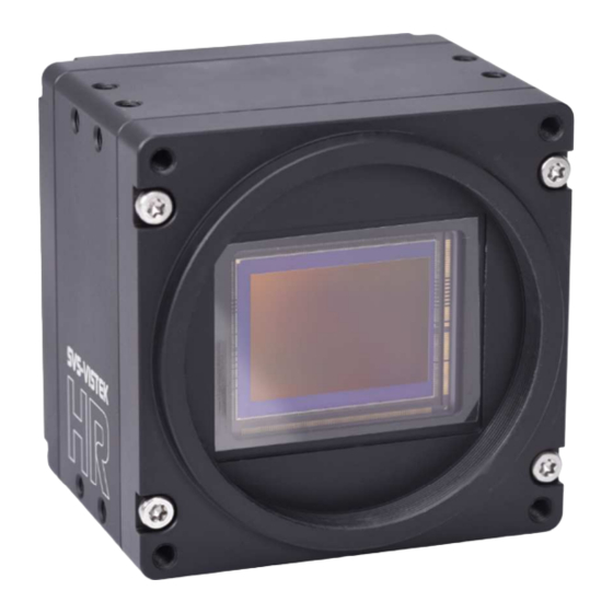
The HR camera series Focusing on details The SVCam HR series is a series of industrial machine vision cameras fea- turing especially on very high image resolutions and interface high speed without compromising on image quality. Camera sensors and interfaces are built to deliver maximum sensor and interface bandwidth. -
Page 9: O Adds Light And Functionality
4I/O adds light and functionality Fig.: 3-1: Illustration of 4I/O concept of switching LEDs Your SVS-Vistek camera is equipped with the innovative 4I/O-interface allowing full light control, replacing external strobe controllers. Each of the outputs can be individually configured and managed using pulse width modulation. With its high current output, the camera is able to drive LED lights directly without external light controller. -
Page 10: Getting Started
Fig.: 4-1: Camera status LED codes Software Further information, documentations, release notes, latest software and applic- ation manuals can be downloaded in the download area on SVS-Vistek down- load area. Depending on the type of camera you bought, several software packages apply. -
Page 11: Svcapture 2
Refer to the SVCam Kit Quick Guide for details. You will find this document in the download area as well. Generally, any GenICam based software package should be able to run a SVS-Vistek camera (GigE Vision, USB3, Camera Link). NOTICE It is recommended to uninstall the existing version of SVCam Kit or SVCap- ture before installing the new version. -
Page 12: Camera Link Viewer Software
1. Run Multicam Studio. 2. Add a new “source” to the application. 3. Select “Camera Link industrial Camera…” 4. Click “Next”. 5. In the list of camera vendors select “SVS-VISTEK“ and the camera you want to view. 4 Getting started... - Page 13 6. Select the frame grabber and connector. 7. For “Topology” values refer to the Euresys documentation. For start, select “Mono” for topology. 8. Choose your connector configuration 9. Click “Finish”. According to your GenICam configuration, the camera image is displayed. INFO For further information on Euresys Multicam Studio refer to the Euresys doc- umentation.
-
Page 14: Firmware Update
“Firmware Update Tool.exe” and the firmware file (download it from website, login area) matching your camera model. Execute firmware update Download the GigE firmware tool and the firmware file from the SVS-Vistek website. Unpack everything into any folder, e.g. “C:\temp”. -
Page 15: Connectors
Connectors Cameras from SVS-Vistek feature a combined I/O and power supply connector (Hirose) and a data connector. Camera Link™ To use Camera Link a frame grabber is needed. INFO Frame grabbers can be purchased at SVS-VISTEK, too. 5.1.1 Camera Link connector... -
Page 16: Camera Link Pinout
5.1.2 Camera Link pinout 5 Connectors... - Page 17 Pinout Signal Descrip- Signal Name Direction tion - 1 - GND / 12 V Shield 1 / 12 V power* Camera to - 2 - Data - 3 - Camera to Data Camera to - 4 - Data - 5 - Xclk- Camera to Transmitter Clock...
- Page 18 Pinout Signal Descrip- Signal Name Direction tion (RS232) - 21 - SerTFG+ Camera to Camera Control (RS232) FG to Cam- - 22 - CC1+ Exsync - 23 - CC2- FG to Cam- Prin (not used) FG to Cam- External Camera - 24 - CC3+ Clock...
- Page 19 Fig.: 5-1: Camera Link pinout & communication 5 Connectors...
-
Page 20: Input / Output Connectors
Input / output connectors NOTICE Make sure your external power supply meets specifications. Voltage must not exceed 25 V. 5 Connectors... -
Page 21: Hirose I/O Connector
5.2.1 Hirose I/O connector The Hirose™ connector provides power, input and output signal access. Max power out is 2 Amperes peak. Fig.: 5-2: I/O Hirose connector layout Inputs and outputs connect via 4I/O-matrix in the GenICam software tree to the appropriate actions. -
Page 22: Feature Description
This chapter covers features of SVCam cameras. Not every feature might be supported by your specific camera model. For information about the features of your specific model, please refer to the specifications area of our website with your exact model. https://www.svs-vistek.com/en/industrial-cameras/svs-svcam-searchresult.php Basic features 6.1.1 Global shutter The shutter is describing the functionality of exposing the light sensitive pixels of the sensor to light for a limited time. - Page 23 Light control with rolling shutter As being said, not all sensor lines are sensitive to light at the same time. Make sure your light is ON as long any pixel are going to e exposed. An exo183xGE i.e. needs about 62ms of minimal scanning time. An exo183xCL i.e. needs about 120ms of minimal scanning time.
-
Page 24: Exposure
Rolling shutter limitations Due to the principles of rolling shutter, some standard features of SVS-Vistek cameras are not applicable. External exposure control (expose while trigger signal active) does not make sense with rolling shutter ROI with rolling shutter: With rolling shutter the whole sensor has to be read out –... -
Page 25: Exposure Speed
6.1.4 Exposure speed Frames per second, or frame rate describes the number of frames output per second (1/ frame time). Especially GigE and USB cameras cannot guarantee predictable maximum frame rates with heavy interface bus load. Maximum frame rate might depend on: Pixel clock Image size Tap structure... -
Page 26: Bit Depth
image to next image will result in a swing of the control loop. Therefore it is not recommended to use the auto-luminance function in such cases. 6.1.7 Bit depth Values of brightness are internally represented by numbers. The number of bits for brightness representation is limiting the number of color values that can be represented. -
Page 27: Resolution
add 6 dB double ISO value 6 dB 400 ISO 12 dB 800 ISO 18 dB 1600 ISO 24 dB 3200 ISO Table: 6-1: Table of dB and corresponding ISO value NOTICE Gain also amplifies the sensor’s noise. Therefore, gain should be last choice for increasing image brightness. -
Page 28: Offset
6.1.10 Offset For physical reasons the output of a sensor will never be zero, even the camera is placed in total darkness or simply closed. Always there will be noise or ran- domly appearing electrons that will be detected as a signal (dark noise: noise generated without light exposure). -
Page 29: Color
6.1.11 Color Color cameras are identical to the monochrome versions. The color pixels are transferred in sequence from the camera, in the same manner as the mono- chrome, but considered as “raw”-format. Fig.: 6-5: Sensor with Bayer pattern The camera sensor has a color mosaic filter called “Bayer” filter pattern named after the person who invented it. -
Page 30: Flip Image
6.1.12 Flip image Images can be mirrored horizontally or vertically. Image flip is done inside the memory of the camera, therefore not increasing the CPU load of the PC. Fig.: 6-6: Original image Fig.: 6-7: Horizontal flip 6 Feature description... -
Page 31: Binning
Fig.: 6-8: Vertical flip 6.1.13 Binning Binning provides a way to enhance dynamic range, but at the cost of lower res- olution. Binning combines electron charges from neighboring pixels directly on the chip, before readout. Binning is only used with monochrome CCD Sensors. For reducing resolution on color sensors refer to "Decimation"... -
Page 32: Decimation
Horizontal binning Accumulates horizontal pixels. Fig.: 6-10: Horizontal binning 2×2 Binning A combination of horizontal and vertical binning. When DVAL signal is enabled only every third pixel in horizontal direction is grabbed. Fig.: 6-11: 2x2 binning 6.1.14 Decimation For reducing width or height of an image, decimation can be used. Columns or rows can be ignored. - Page 33 Fig.: 6-12: Horizontal decimation Fig.: 6-13: Vertical decimation Decimation on color sensors The Bayer pattern color information is preserved with 1/3 horizontal and vertical resolution. The frame readout speed increases approx. by factor 2.5. Fig.: 6-14: Decimation on color sensors 6 Feature description...
-
Page 34: Genicam
With your SVCam, the GenICam tree does have some hardware related exten- sions, especially in the I/O sector. See the Quick guide install for a short intro- duction into the SVS-Vistek GenICam tree. The GenICam properties are organized in views. The recommended way to view and adjust is by using SVCapture. -
Page 35: Trigger Modes
Default input is Input1 for trigger. At the rising edge of the trigger the camera will initiate the exposure. The software provided by SVS-Vistek allows the user to set exposure time e.g. from 60 μs to 60 sec (camera type dependent). - Page 36 Exposure time can be changed during operation. No frame is distorted during switching time. If the configuration is saved to the EEPROM, the set exposure time will remain also when power is removed. Details of external trigger mode Diagrams below are equivalent for CCD and CMOS technique. 6 Feature description...
- Page 37 6 Feature description...
-
Page 38: Shutter Modes
6.1.17 Shutter modes CCD and CMOS area cameras consist of pixels, ordered in lines and columns. All pixel are exposed to light and then read out to camera electronics. There is a difference of reading out the sensor between global and rolling shutter. Espe- cially flashing and moving objects might need more attention with rolling shut- ter. - Page 39 interface). Nonetheless, the maximum achievable frame rate with applied ROI will be the maximum frame rate of the sensor reading the full sensor area (internal full sensor speed), please refer to relating sensor specs. Artifacts All pixel show same artifacts Deformed image of moving objects Exposure with flash Fig.: 6-15: flash control with rolling shutter...
- Page 40 Light control with rolling shutter As being said, not all sensor lines are sensitive to light at the same time. Make sure your light is ON as long any pixel are going to e exposed. An exo183xGE i.e. needs about 62ms of minimal scanning time. An exo183xCL i.e. needs about 120ms of minimal scanning time.
- Page 41 Rolling shutter limitations Due to the principles of rolling shutter, some standard features of SVS-Vistek cameras are not applicable. External exposure control (expose while trigger signal active) does not make sense with rolling shutter ROI with rolling shutter: With rolling shutter the whole sensor has to be read out –...
- Page 42 Global reset release mode is a special mode to operate rolling shutter sensors. With the exception of the hr120, all rolling shutter cameras from SVS-Vistek GmbH can be operated in Global Reset Release mode. Global reset release shows advantages when operating light sources in non-constant light situ- ations.
- Page 43 Global reset release mode setup make sure of no external (constant) light source use flash only for object illumination set camera to global reset release mode start exposure time together with flash (flash strobe in darkness) When flashing in global reset mode, the flash time will define the exposure time. Thus, an very time-stable flash control is essential.
-
Page 44: Camera Features
Camera features The camera features of the HR series are defined by the combination of its elec- tronics and firmware features. Firmware features can be upgraded with new firmware releases. 6 Feature description... -
Page 45: Basic Capture Modes
6.2.1 Basic capture modes The camera has 2 basic operation modes. Free run (timed) run: The camera will expose and deliver images on a fixed schedule. Triggered: The camera will wait for an external signal and start exposure after receiving the external trigger signal. - Page 46 At the rising edge of the trigger the camera will initiate the exposure. The software provided by SVS-Vistek allows the user to set exposure time e.g. from 60 μs to 60 sec (camera type dependent). Exposure time of the next image can overlap with the frame readout of the cur- rent image (trigger pulse occurs when FVAL is high).
- Page 47 When the rising edge of trigger signal occurs after frame readout has ended (FVAL is low), the start of exposure time is not synchronized to LVAL and expos- ure time starts after a short and persistent delay. Exposure time can be changed during operation. No frame is distorted during switching time.
-
Page 48: System Clock Frequency
Fig.: 6-23: Mode 1: External trigger with pulse width exposure control (overlap) Fig.: 6-24: Mode 1: External trigger with programmable exposure time (non-overlap) Fig.: 6-25: Mode 1: External trigger with programmable exposure time (overlap) 6.2.2 System clock frequency Default system clock frequency in almost every SVCam is set to 66.6 MHz. To validate your system frequency refer to: specifications. -
Page 49: Temperature Sensor
INFO Use multiples of 15 ns to write durations into camera memory. 6.2.3 Temperature sensor A temperature sensor is installed on the main board of the camera. To avoid overheating, the temperature is constantly monitored and read. Besides soft- ware monitoring, the camera indicates high temperature by a red flashing LED (see flashing LED codes). - Page 50 Fig.: 6-27: Detailed view of LVAL signal timing on Camera Link > (1920 / 2) × (1/85MHz) px in line / sent at CL_clock once (1/85e × ≈ 11,29 µs Table: 6-2: Example calculation > 3 × (1/85MHz) (3/85e ≈ 35,3 ns time between two valid line data packages...
-
Page 51: Look-Up Table
6.2.5 Look-up table The look-up table feature (LUT) lets the user define certain values to every bit value that comes from the ADC. To visualize a LUT a curve diagram can be used, similar to the diagrams used in photo editing software. - Page 52 Historically gamma correction was used to correct the illumination behavior of CRT displays, by compensating brightness-to-voltage with a gamma value between 1,8 up to 2,55. The gamma algorithms for correction can simplify resolution shifting as shown seen below. Input & output signal range from 0 to 1 Gamma Output-signal = Input-signal Fig.: 6-29: Several gamma curves comparable to a LUT...
-
Page 53: Roi / Aoi
6.2.6 ROI / AOI In partial scan mode or Area-Of-Interest (AOI) mode (or Region-Of-Interest (ROI) mode) only a certain region of the sensor will be read. Fig.: 6-30: AOI on area sensor Selecting an AOI will reduce the number of horizontal lines being read. This will reduce the amount of data to be transferred, thus increasing the maximum speed in terms of frames per second. - Page 54 White balance gets much more difficult. Con- trast is lower. INFO SVS-VISTEK recommends IR cut filter for high demands on sharpness with monochrome or color sensors. Spectral impact of IR cut filters IR cut filter do influence the spectral sensitivity of the sensor. The spectral graph below shows the wavelength relative impact of the SVS-VISTEK stand- ard filter.
-
Page 55: I/O Features
With your SVCam, the GenICam tree does have some hardware related exten- sions, especially in the I/O sector. See the Quick guide install for a short intro- duction into the SVS-Vistek GenICam tree. The GenICam properties are organized in views. The recommended way to view and adjust is by using SVCapture. -
Page 56: Assigning I/O Lines - Iomux
NOTICE All modfications in the GenICam tree will have immediate effect. 6.3.2 Assigning I/O Lines – IOMUX The IOMUX is best described as a switch matrix. It connects inputs, and outputs with the various functions of SVCam I/O. It also allows combining inputs with Boolean arguments. - Page 57 LineSelector Translation Line18 Pulse0 Line19 Pulse1 Line20 Pulse2 Line21 Pulse3 Line22 Uart2 In The input and output lines for Strobe and Trigger impulses can be arbitrarily assigned to actual data lines. Individual assignments can be stored persistently to the EPROM. Default setting can be restored from within the Camera. INFO Refer to pin-out in input / output connectors when physically wiring.
- Page 58 Input vector to switch matrix Name Description io_in(0) trigger input 0 – 24 Volt / RS-232 / opto * io_in(1) trigger input 0 – 24 Volt / RS-232 / opto * io_in(2) trigger input 0 – 24 Volt / RS-232 / opto * io_in(3) trigger input 0 –...
- Page 59 Output vector from switch matrix Name / register Description io_out(0) output open drain io_out(1) output open drain io_out(2) output open drain * io_out(3) output open drain * io_txd output, when debug='0' rxd_to_uart1 output (uart_in) trigger output sequenzer_hw_trigger input to module iomux_sequenzer_0 debounce input input to module iomux_dfilter_0 prescale input...
- Page 60 Example of an IOMUX configuration Fig.: 6-33: Example of an IOMUX configuration The trigger signal comes in on line 0 Debounce it. connect line 0 to 8: 1000000000000000000000000 signal appears again on line 15 – debouncer out Use the prescaler to act only on every second pulse. connect line 16 to 9.
- Page 61 Inverter The inverter enabled at a certain line provides the reverse signal to or from a module. Set to “1” With set to “1” enabled in a certain line, this line will provide a high signal no mat- ter what signal was connected to the line before. Set to “1”...
- Page 62 6.3.3 During Pulse Width Modulation (PWM), a duty cycle is modulated by a fixed fre- quency square wave. This describes the ratio of ON to OFF as duty factor or duty ratio. Why PWM? Pulse width modulation is an extremely efficient way (in terms of power dis- sipation) to provide/regulate electrical power to consumers as long as they do not need uninterrupted supply (such as diodes or LEDs).
- Page 63 Fig.: 6-34: PWM intensity Examples of PWMs The integrals over both periods are equal. An equal amount of Photons will be emitted. The intensity of light is the same. The periods are equal in length. 6 Feature description...
- Page 64 Fig.: 6-35: Example: 25% PWM load Fig.: 6-36: Example: 50% PWM load 6 Feature description...
- Page 65 Fig.: 6-37: Example: 75% PWM load The PWM module Fig.: 6-38: The PWM module 6 Feature description...
-
Page 66: Led Strobe Control
6.3.4 LED strobe control The SVCam 4I/O concept contains an integrated strobe controller. Its controls are integrated into the GenICam tree. With LED lights attached to the outputs, this enables the user to control the light without external devices. Being con- trolled via GenICam, any GenICam-compliant 3 party software is able to con- trol the light as well. - Page 67 Total power ( 2,75 W Power at LEDs ( 3,25 W Power loss at resistor ( Table: 6-5: Example Calculation “No Flash” (CW Mode) LEDs in flash mode Most LED lights can cope with currents higher than specs. This gives you higher light output when light is ON.
-
Page 68: Sequencer
6.3.5 Sequencer The sequencer is used when different exposure settings and illuminations are needed in a row. Values to set Description Sequencer interval Duration of the interval Exposure start Exposure delay after interval start Exposure stop Exposure stop related to interval Start Strobe start Strobe delay after interval start Strobe stop... - Page 69 I/O matrix 4 images to be taken (RGBW) result in 4 sequences RGB PWM change with different intensities (duty cycle) taking care for dif- ferences in spectral response of the camera sensor PWM change 0-2 is connected to out 0-2 Seq pulse A is driving the exposure (trigger) Seq pulse B is driving the strobe Seq pulse B in WHITE sequence is reduced down to 33% as light intens-...
- Page 70 Values to set in GenICam prop- Interval 0 Interval 1 Interval 2 Interval 3 erties (RED) (GREEN) (BLUE) (WHITE) Sequencer Interval 66666667 tic 66666667 tic 66666667 tic 66666667 tic (1000 ms) (1000 ms) (1000 ms) (1000 ms) 0 tic 0 tic 6666667 tic 0 tic Seq pulse A start...
- Page 71 Sequencer setup with SVCapture Starting with SVCapture 2.5.2, there is a sequencer assistant, providing easy setup of the sequencer settings. The assistant will help you to setup timings for start exposure and lighting and so on. The PWMs are connected to the physical outputs (e.g.
- Page 72 Feature name Feature value Acquisition Control - Continuous Acquisition Mode Acquisition Control – Trigger Selector - Trigger Mode Acquisition Control – Line 1 Trigger Selector - Trigger Source Acquisition Control – Trigger Selector – Trigger Width Exposure Mode Enhanced IO – PWMEnable Enhanced IO –...
-
Page 73: Optical Input
If your camera trigger is in the ms range or slower, we recommend to use the optical input. An optical input needs some current for operation. The SVS-Vistek optical input is specified to 5-24 V, 8 mA. Fig.: 6-41: Optical input The optocoupler galvanically separates electrical circuits by emitting light on one side and interpreting light in the other. - Page 74 Do it in the GenICam tree The logic function always combines the values of Digital IO InputA/LogicA and InputB/LogicB. In case of the Trigger enable logic function, LogicB is the trigger enable signal and will be combined with LogicA value. NAND XNOR A B Y...
-
Page 75: Serial Data Interfaces
6.3.8 Serial data interfaces (ANSI EIA/) TIA-232-F RS-232 and RS-422 (from EIA, read as Radio Sector or commonly as Recom- mended Standard) are technical standards to specify electrical characteristics of digital signaling circuits. Serial connection might be used to control SVCams. These signals are used to send low-power data signals to control exposure, light or lenses (MFT). -
Page 76: Trigger-Edge Sensitivity
6.3.9 Trigger-edge sensitivity Trigger-edge sensitivity is implemented by a “Schmitt trigger”. Instead of trig- gering to a certain value, the Schmitt trigger provides a threshold. Fig.: 6-43: Schmitt trigger noise suppression 6 Feature description... -
Page 77: Debouncing Trigger Signals
6.3.10 Debouncing trigger signals Bounces or glitches caused by a switch can be avoided by software within the SVCam. Fig.: 6-44: Bounces or glitches caused by a switch Therefore the signal will not be accepted until it lasts at least a certain time. >... - Page 78 Input 1 debounce time here is about 1ms. The debouncer module Fig.: 6-46: The debouncer module 6 Feature description...
-
Page 79: Prescale
6.3.11 Prescale The Prescale function can be used for masking off input pulses by applying a divisor with a 4-bit word, resulting in 16 unique settings. Reducing count of interpreted trigger signal Use the prescale function to ignore a certain count of trigger signals. Divide the amount of trigger signals by setting a divisor. -
Page 80: Dimensions
Dimensions INFO All length units in mm. Find the technical drawings in the web download area at https://www.svs-vistek.com/en/support/svs-support-download-center.php CAD step files available with valid login at SVS-VISTEK.com M58 mount Diameter 58 mm Thread pitch 0.75 mm Back focus distance from sensor to flange of the camera: 11.48 mm Distance from sensor surface to lens differs depending on lens spe- cifications and how far the lens is screwed in. -
Page 81: Hr16050*Cl, Hr16070*Cl, Hr29050*Cl
hr16050*CL, hr16070*CL, hr29050*CL 7 Dimensions... - Page 82 7 Dimensions...
- Page 83 7 Dimensions...
-
Page 84: Hr25*Cl
hr25*CL 7 Dimensions... - Page 85 7 Dimensions...
- Page 86 7 Dimensions...
- Page 87 hr49*CL 7 Dimensions...
- Page 88 7 Dimensions...
- Page 89 7 Dimensions...
- Page 90 hr65*CL 7 Dimensions...
- Page 91 7 Dimensions...
- Page 92 7 Dimensions...
- Page 93 hr120*CL INFO The HR120 can be ordered with different mount options. The most general approach is M58, as outlined in the drawing below. Additional mounts (Birger mount, Moritex mount) on request. 7 Dimensions...
- Page 94 7 Dimensions...
- Page 95 7 Dimensions...
- Page 96 Appendix I/O driver circuit schematics Camera power supply and power supply for PWM out is 25V max. Power for PWM out has to be supplied via Hirose connector. The open drain outputs are ledged to ground, that means you connect your LED on the positive side to your (light-)power source, the negative LED connector goes to the camera out.
Need help?
Do you have a question about the HR Series and is the answer not in the manual?
Questions and answers