Table of Contents
Advertisement
Quick Links
Advertisement
Table of Contents

Related Manuals for SVS-Vistek HR 10GigE


Summary of Contents for SVS-Vistek HR 10GigE
- Page 1 Manual HR 10GigE hr387, hr342, hr455, hr51...
-
Page 2: Table Of Contents
Content Company information Standards Disclaimer Copyright notice Legal information USA and Canada Europe The HR camera series Focusing on details 10 GigE Vision Speed is king Optimized network adapter tuning 4I/O adds light and functionality Use of Canon lenses Connectors GigE IP Setup 4.1.1 Automatic camera detection... - Page 3 5.3.1 Power safety 5.3.2 Connect the camera Camera status LED codes Software and firmware 5.5.1 SVCapture 2.x 5.5.2 Software development kit 5.5.3 Firmware update Feature description Basic features 6.1.1 Gain 6.1.2 Resolution 6.1.3 Offset 6.1.4 Color 6.1.5 Flip image 6.1.6 Binning 6.1.7 Decimation...
- Page 4 6.3.5 Sequencer 6.3.6 Optical input 6.3.7 PLC / Logical operation on inputs 6.3.8 Serial data interfaces 6.3.9 Trigger-edge sensitivity 6.3.10 Debouncing trigger signals 6.3.11 Prescale 6.3.12 Trigger modes Camera features Dimensions M58 mount hr387XGE hr342XGE hr51XGE hr455XGE hr65XGE Appendix I/O driver circuit schematics IP protection classes...
-
Page 5: Company Information
The camera in your possession has been produced with great care and has been thoroughly tested. Nonetheless, in case of any complaint, please contact your local SVS-VISTEK distributor. You will find a list of distributors in your area on www.svs-vistek.com... -
Page 6: Copyright Notice
Copyright notice Forwarding and duplicating of this document, as well as using or revealing its con- tents are prohibited without written approval. All rights reserved with regard to pat- ent claims or submission of design or utility patent. 1 Company information... -
Page 7: Legal Information
Customers, integ- rators and end users of SVS-Vistek products might sell these products and agree to do so at their own risk, as SVS-Vistek will not take any liability for any damage from improper use or sale. -
Page 8: The Hr Camera Series
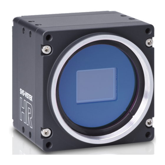
The HR camera series Focusing on details The SVCam HR series is a series of industrial machine vision cameras featuring especially on very high image resolutions and interface high speed without com- promising on image quality. Camera sensors and interfaces are built to deliver maximum sensor and interface bandwidth. -
Page 9: O Adds Light And Functionality
4I/O adds light and functionality Fig.: 3-1: Illustration of 4I/O concept of switching LEDs Your SVS-Vistek camera is equipped with the innovative 4I/O-interface allowing full light control, replacing external strobe controllers. Each of the outputs can be individually configured and managed using pulse width modulation. With its high current output, the camera is able to drive LED lights directly without external light controller. -
Page 10: Connectors
For finding and accessing your camera, start SVCapture on your computer. As soon as the camera has booted, all SVS-Vistek GigE cameras are showing up in the main window. Select the camera you want to connect to and press ok. - Page 11 Manual IP configuration will permit you to Assign a new IP address (make sure the new address is unique and valid in the current subnet) Save a specific address as a permanent address to the camera (Persistent) Save automatic address mode or the manually configured address to the camera For saving an persistent IP configuration (configuration will survive power off) you need to check the „Persistent IP address“.
-
Page 12: Gige Vision
GigE Vision 4.2.1 Network (TCP/IP) Address Assignment By default, the camera does not have a persistent IP address. When forcing an IP address by using the PC internal network dialog, changes are only valid until the next restart of the Camera. For a peer-to-peer connection of a GigE camera to a PC a network address assign- ment based on LLA (Local Link Address) is recommended. - Page 13 Fig.: 4-3: Connecting multiple cameras on multi NICs Multiple cameras connected by a switch To connect multiple cameras by a switch, the switch must be managed. It might also be necessary to operate the cameras in an “inter packet delay” applying a smother image data stream.
-
Page 14: Xml Files
camera and distributes it to multiple destinations in this mode. Since a GigE camera always needs a single controlling application, there will be only one master application. The controlling master application has to open a cam- era in multicast mode (IP 232.x.x.x for local multicast groups) in order to allow other applications to connect to the same image data stream. -
Page 15: 10Gige Limitations And Issues
Special NICs support 100% connections without frame drops. 4.3.3 Recommended setup It is recommended to use a 10GigE Ethernet card with grabber capabilities. All SVS-Vistek certification setups are using this kind of cards. Contact sales@svs-vistek.com for details and more recommendations. -
Page 16: Hirose I/O Connector
Hirose I/O connector The Hirose™ connector provides power, input and output signal access. Max power out is 2 Amperes peak. Fig.: 4-6: I/O Hirose connector layout Inputs and outputs connect via 4I/O-matrix in the GenICam software tree to the appropriate actions. For detailed information about switching lights with the power outputs via GenICam, refer to "LED strobe control"... -
Page 17: Getting Started
Power supply For safety reasons, for protection of the camera and users, use certified power supplies only. Please refer to specifications for your camera model. Appropriate power supplies can be ordered at SVS-VISTEK GmbH. 5.3.1 Power safety The camera does not have a power switch. The camera is powered on as soon power is available to the camera. -
Page 18: Camera Status Led Codes
Generally external power supply for USB3 Vision, CoaXPress (if PoCXP enabled) or PoE cameras is not needed. Nonetheless, you might want to use a separate power on the Hirose connector to reduce load on the data port. The external power on the Hirose connector is the preferred power source. The power up is defined as follows: Power over USB3, CoaXPress port or GigE port (with PoE) or on the Hirose connector will power on the camera... -
Page 19: Software And Firmware
C/C# programming libs and interface SVCapture 2.x is a GenICam/XML based software tool provided for free. It is cre- ated to show the capabilities of your SVS-Vistek camera and to show/modify val- ues to your cam. Get control of exposure timing, trigger delay, image correction etc. or control up to 4 LED lights connected to the SVCam directly via "GenICam"... - Page 20 3. Choose destination folder and select necessary modules / drivers. The TLxxx modules are the GenTL drivers, necessary as well if you want to use SVS-Vistek driver with third party software. 4. In case of system warnings regarding modification of USB3 drivers or GigE/10GigE filter drivers: The specified performance is possible only with these highly optimized drivers.
- Page 21 Initialization First launch 1. Connect the camera to your computer. In case of a new USB3 camera driver hardware installation notice will pop up. 2. Start SVCapture. SVCapture will try to discover your camera. 3. Click on the camera being found and you’re connected. Depending on your interface type, with TL Settings you are able to adjust which interface types should be included in the camera discover process.
- Page 22 NOTICE If you have installed third-party GenTL drivers (e.g. Euresys CoaXPress or Camera Link drivers), they should be selectable as well. This works only if thir-party software has been installed before SVCapture. 4. Find and adjust your camera features in the GenICam tree. Click and adjust items by number (1.) or slider (2.) and start grabbing images from the camera.
-
Page 23: Software Development Kit
C:\Program Files\SVS-VISTEK GmbH\SVCam Kit\SDK INFO Refer to the “Getting started with SDK” manual for first steps in programming your SVS-Vistek camera. This document should be included in the docs section of your installation. The following platforms are supported: X86 (Windows, Linux, MacOS support on request) -
Page 24: Firmware Update
“Firmware Update Tool.exe” and the firmware file (download it from website, login area) matching your camera model. Execute firmware update Download the GigE firmware tool and the firmware file from the SVS-Vistek website. Unpack everything into any folder, e.g. “C:\temp”. - Page 25 Fig.: 5-3: Firmware update 5 Getting started...
-
Page 26: Feature Description
For information about the features of your specific model, please refer to the specifications area of our website with your exact model. https://www.svs-vistek.com/en/industrial-cameras/svs-svcam-searchresult.php Basic features This section covers basic functionality of area sensor cameras. -
Page 27: Gain
6.1.1 Gain Setting gain above 0 dB (default) is a way to boost the signal coming from the sensor. Especially useful for low light conditions. Setting gain amplifies the signal of individual or binned pixels before the ADC. Referring to photography adding gain corresponds to increasing ISO. -
Page 28: Offset
The amount of dark current in these areas is used to adjust the offset (see "Off- set" below). For calculating image sizes, the maximum camera resolution is determining max- imum image resolution, refer to the specifications of the camera model). 6.1.3 Offset For physical reasons the output of a sensor will never be zero, even the camera is... -
Page 29: Color
6.1.4 Color Color cameras are identical to the monochrome versions. The color pixels are transferred in sequence from the camera, in the same manner as the mono- chrome, but considered as “raw”-format. Fig.: 6-3: CCD with Bayer pattern The camera sensor has a color mosaic filter called “Bayer” filter pattern named after the person who invented it. - Page 30 Fig.: 6-4: Original image Fig.: 6-5: Horizontal flip 6 Feature description...
-
Page 31: Binning
Fig.: 6-6: Vertical flip 6.1.6 Binning Binning provides a way to enhance dynamic range, but at the cost of lower res- olution. Binning combines electron charges from neighboring pixels directly on the chip, before readout. Binning is only used with monochrome CCD Sensors. For reducing resolution on color sensors refer to "Decimation"... -
Page 32: Decimation
Horizontal binning Accumulates horizontal pixels. Fig.: 6-8: Horizontal binning 2×2 Binning A combination of horizontal and vertical binning. When DVAL signal is enabled only every third pixel in horizontal direction is grabbed. Fig.: 6-9: 2x2 binning 6.1.7 Decimation For reducing width or height of an image, decimation can be used. Columns or rows can be ignored. - Page 33 Fig.: 6-10: Horizontal decimation Fig.: 6-11: Vertical decimation Decimation on color sensors The Bayer pattern color information is preserved with 1/3 horizontal and vertical resolution. The frame readout speed increases approx. by factor 2.5. Fig.: 6-12: Decimation on color sensors 6 Feature description...
-
Page 34: Genicam
With your SVCam, the GenICam tree does have some hardware related exten- sions, especially in the I/O sector. See the Quick guide install for a short intro- duction into the SVS-Vistek GenICam tree. The GenICam properties are organized in views. The recommended way to view and adjust is by using SVCapture. -
Page 35: Trigger Modes
Default input is Input1 for trigger. At the rising edge of the trigger the camera will initiate the exposure. The software provided by SVS-Vistek allows the user to set exposure time e.g. from 60 μs to 60 sec (camera type dependent). - Page 36 Exposure time can be changed during operation. No frame is distorted during switching time. If the configuration is saved to the EEPROM, the set exposure time will remain also when power is removed. Details of external trigger mode Diagrams below are equivalent for CCD and CMOS technique. 6 Feature description...
- Page 37 6 Feature description...
-
Page 38: Shutter Modes
6.1.10 Shutter modes CCD and CMOS area cameras consist of pixels, ordered in lines and columns. All pixel are exposed to light and then read out to camera electronics. There is a difference of reading out the sensor between global and rolling shutter. Especially flashing and moving objects might need more attention with rolling shutter. - Page 39 Nonetheless, the maximum achievable frame rate with applied ROI will be the maximum frame rate of the sensor reading the full sensor area (internal full sensor speed), please refer to relating sensor specs. Artifacts All pixel show same artifacts Deformed image of moving objects Exposure with flash Fig.: 6-13: flash control with rolling shutter Flash strobe on whole exposure time...
- Page 40 Light control with rolling shutter As being said, not all sensor lines are sensitive to light at the same time. Make sure your light is ON as long any pixel are going to e exposed. An exo183xGE i.e. needs about 62ms of minimal scanning time. An exo183xCL i.e. needs about 120ms of minimal scanning time.
- Page 41 Rolling shutter limitations Due to the principles of rolling shutter, some standard features of SVS-Vistek cameras are not applicable. External exposure control (expose while trigger signal active) does not make sense with rolling shutter ROI with rolling shutter: With rolling shutter the whole sensor has to be read out –...
- Page 42 Global Reset Release Mode Global reset release mode is a special mode to operate rolling shutter sensors. All rolling shutter cameras from SVS-VISTEK GmbH can be operated in Global Reset Release mode. Global reset release shows advantages when operating light sources in non-constant light situations.
-
Page 43: Exposure
Fig.: 6-16: strobe control in global reset mode In Global Reset Mode flash is starting together with exposure, all CMOS lines are sensitive to light. Flash time has to be shorter than exposure time. Exposure time is determined by flash time. INFO Strobe control jitter might be visible in the image as brightness instabilities. - Page 44 6 Feature description...
-
Page 45: Acquisition And Processing Time
6.1.13 Acquisition and processing time The camera has to read the sensor, process the data to a valid image and transfer this to the host computer. Some of these tasks are done in parallel. This implies the data transfer does not end immediately after end of exposure, as the image has to be processed and transferred after exposure. -
Page 46: Bit Depth
6.1.15 Bit depth Values of brightness are internally represented by numbers. The number of bits for brightness representation is limiting the number of color values that can be represented. Bit depth defines the max- imum unique colors or gray levels in an image. bit depth No of gray values = 2 All SVCam models support 8-bit format. -
Page 47: Camera Features
NOTICE Unpacking has to be done manually, this is not a GenTL function. Thus, image acquisition in packed formats won’t be supported by most 3 party software products. Camera features The camera is embedded in its electronics and firmware feature. 6.2.1 Glass filter The camera is equipped with a glass filter for sensor protection reasons (dust). - Page 48 In the host computer: significant loss of dynamic range In the camera, digital: better (smoother) shading than on computer, still loss of dynamic range In the camera, analog: set gain/offset locally direct on sensor to get optimum shading correction with only small changes in dynamic range It is important to have in mind that shading correction might reduce dynamic range of the images taken.
- Page 49 Fig.: 6-18: Shading control disabled 2. With SVCapture load these reference images. 3. See shading in the preview 4. Generate the shading map 5. Save map to disk. This file can be used in programmed environments via SDK as well. 6.
-
Page 50: Defect Pixel Correction
The amount of hot pixels is proportional to exposure time and temperature of the sensor. By default, all known defect pixels or clusters are corrected by SVS-VISTEK as a factory default. Under challenging conditions or high temperature environments defect pixel beha- viour might change. - Page 51 Fig.: 6-19: Illustration of a defect pixel Procedure of pixel correction SVCapture is the tool to generate pixel correction maps. The pixel correction assistant provides everything to create, load, enable and restore defect pixel cre- ation maps. Defect pixel correction is possible with certain models only. See camera specs whether your model does support this.
- Page 52 For easy image processing, it is recommended to have pixel correction activ- ated Pixel correction maps can be saved and loaded The std factory map can be selected any time Generate your own custom map Select your own defect pixel map The procedure to create a std map is pretty straight forward.
- Page 53 1. Load black images (16 images minimum) into generator 2. Generate map 3. Save map to file for later usage 4. Upload the map to the camera. Make sure pixel correction is activated. Procedure of pixel correction SVCapture is the tool to generate pixel correction maps. The pixel correction assistant provides everything to create, load, enable and restore defect pixel cre- ation maps.
- Page 54 For easy image processing, it is recommended to have pixel correction activ- ated Pixel correction maps can be saved and loaded The std factory map can be selected any time Generate your own custom map Select your own defect pixel map The procedure to create a std map is pretty straight forward.
-
Page 55: Look-Up Table
6.2.4 Look-up table The look-up table feature (LUT) lets the user define certain values to every bit value that comes from the ADC. To visualize a LUT a curve diagram can be used, similar to the diagrams used in photo editing software. - Page 56 Historically gamma correction was used to correct the illumination behavior of CRT displays, by compensating brightness-to-voltage with a gamma value between 1,8 up to 2,55. The gamma algorithms for correction can simplify resolution shifting as shown seen below. Input & output signal range from 0 to 1 Gamma Output-signal = Input-signal Fig.: 6-21: Several gamma curves comparable to a LUT...
-
Page 57: Roi / Aoi
6.2.5 ROI / AOI In partial scan mode or Area-Of-Interest (AOI) mode (or Region-Of-Interest (ROI) mode) only a certain region of the sensor will be read. Fig.: 6-22: AOI on area sensor Selecting an AOI will reduce the number of horizontal lines being read. This will reduce the amount of data to be transferred, thus increasing the maximum speed in terms of frames per second. -
Page 58: Basic Capture Modes
6.2.6 Basic capture modes The camera has 2 basic operation modes. Free run (timed) run: The camera will expose and deliver images on a fixed schedule. Triggered: The camera will wait for an external signal and start exposure after receiving the external trigger signal. - Page 59 Exposure time of the next image can overlap with the frame readout of the current image (rising edge of trigger pulse occurs when FVAL is high). When this hap- pens: the start of exposure time is synchronized to the falling edge of the LVAL signal.
-
Page 60: Trigger Modes
Default input is Input1 for trigger. At the rising edge of the trigger the camera will initiate the exposure. The software provided by SVS-Vistek allows the user to set exposure time e.g. from 60 μs to 60 sec (camera type dependent). - Page 61 Exposure time can be changed during operation. No frame is distorted during switching time. If the configuration is saved to the EEPROM, the set exposure time will remain also when power is removed. Details of external trigger mode Diagrams below are equivalent for CCD and CMOS technique. 6 Feature description...
-
Page 62: Read-Out Control
6.2.8 Read-out control Read-out control defines a delay between exposure and data transfer. Read-out control is used to program a delay value (time) for the readout from the sensor. With more than one camera connected to a single computer, image acquisition and rendering can cause conflicts for data transfer, on CPU or bus system. -
Page 63: Predefined Configurations (User Sets)
6.2.11 Predefined configurations (user sets) The camera starts with default values for all features when turned on. Settings made during operation will expire when the camera is turned off. All preset adjustments are located in the GenICam tree in the “User Set Control” property. -
Page 64: Burst Mode
(not applicable to USB cameras) INFO As soon as the internal memory buffer is filled up, frames will be dropped. Due to this, SVS-Vistek cameras provide up to 512 MB image buffer memory. 6 Feature description... -
Page 65: I/O Features
With your SVCam, the GenICam tree does have some hardware related exten- sions, especially in the I/O sector. See the Quick guide install for a short intro- duction into the SVS-Vistek GenICam tree. The GenICam properties are organized in views. The recommended way to view and adjust is by using SVCapture. -
Page 66: Assigning I/O Lines - Iomux
6.3.2 Assigning I/O Lines – IOMUX The IOMUX is best described as a switch matrix. It connects inputs, and outputs with the various functions of SVCam I/O. It also allows combining inputs with Boolean arguments. Fig.: 6-27: "IN0" connected to "debouncer" Now the debounced signal can be taken from Debouncer (line 8) in the next mod- ule as source. - Page 67 LineSelector Translation Line20 Pulse2 Line21 Pulse3 Line22 Uart2 In The input and output lines for Strobe and Trigger impulses can be arbitrarily assigned to actual data lines. Individual assignments can be stored persistently to the EPROM. Default setting can be restored from within the Camera. INFO Refer to pin-out in input / output connectors when physically wiring.
- Page 68 Input vector to switch matrix Name Description io_in(0) trigger input 0 – 24 Volt / RS-232 / opto * io_in(1) trigger input 0 – 24 Volt / RS-232 / opto * io_in(2) trigger input 0 – 24 Volt / RS-232 / opto * io_in(3) trigger input 0 –...
- Page 69 Output vector from switch matrix Name / register Description io_out(0) output open drain io_out(1) output open drain io_out(2) output open drain * io_out(3) output open drain * io_txd output, when debug='0' rxd_to_uart1 output (uart_in) trigger output sequenzer_hw_trigger input to module iomux_sequenzer_0 debounce input input to module iomux_dfilter_0 prescale input...
- Page 70 Example of an IOMUX configuration Fig.: 6-28: Example of an IOMUX configuration The trigger signal comes in on line 0 Debounce it. connect line 0 to 8: 1000000000000000000000000 signal appears again on line 15 – debouncer out Use the prescaler to act only on every second pulse. connect line 16 to 9.
- Page 71 Inverter The inverter enabled at a certain line provides the reverse signal to or from a module. Set to “1” With set to “1” enabled in a certain line, this line will provide a high signal no mat- ter what signal was connected to the line before. Set to “1”...
- Page 72 6.3.3 During Pulse Width Modulation (PWM), a duty cycle is modulated by a fixed fre- quency square wave. This describes the ratio of ON to OFF as duty factor or duty ratio. Why PWM? Pulse width modulation is an extremely efficient way (in terms of power dis- sipation) to provide/regulate electrical power to consumers as long as they do not need uninterrupted supply (such as diodes or LEDs).
- Page 73 Fig.: 6-29: PWM intensity Examples of PWMs The integrals over both periods are equal. An equal amount of Photons will be emitted. The intensity of light is the same. The periods are equal in length. 6 Feature description...
- Page 74 Fig.: 6-30: Example: 25% PWM load Fig.: 6-31: Example: 50% PWM load 6 Feature description...
- Page 75 Fig.: 6-32: Example: 75% PWM load The PWM module Fig.: 6-33: The PWM module 6 Feature description...
-
Page 76: Led Strobe Control
6.3.4 LED strobe control The SVCam 4I/O concept contains an integrated strobe controller. Its controls are integrated into the GenICam tree. With LED lights attached to the outputs, this enables the user to control the light without external devices. Being controlled via GenICam, any GenICam-compliant 3 party software is able to control the light as well. - Page 77 Total power ( 2,75 W Power at LEDs ( 3,25 W Power loss at resistor ( Table: 6-3: Example Calculation “No Flash” (CW Mode) LEDs in flash mode Most LED lights can cope with currents higher than specs. This gives you higher light output when light is ON.
-
Page 78: Sequencer
6.3.5 Sequencer The sequencer is used when different exposure settings and illuminations are needed in a row. Values to set Description Sequencer interval Duration of the interval Exposure start Exposure delay after interval start Exposure stop Exposure stop related to interval Start Strobe start Strobe delay after interval start Strobe stop... - Page 79 I/O matrix 4 images to be taken (RGBW) result in 4 sequences RGB PWM change with different intensities (duty cycle) taking care for dif- ferences in spectral response of the camera sensor PWM change 0-2 is connected to out 0-2 Seq pulse A is driving the exposure (trigger) Seq pulse B is driving the strobe Seq pulse B in WHITE sequence is reduced down to 33% as light intensities...
- Page 80 Values to set in GenICam prop- Interval 0 Interval 1 Interval 2 Interval 3 erties (RED) (GREEN) (BLUE) (WHITE) Sequencer Interval 66666667 tic 66666667 tic 66666667 tic 66666667 tic (1000 ms) (1000 ms) (1000 ms) (1000 ms) 0 tic 0 tic 6666667 tic 0 tic Seq pulse A start...
- Page 81 Sequencer setup with SVCapture Starting with SVCapture 2.5.2, there is a sequencer assistant, providing easy setup of the sequencer settings. The assistant will help you to setup timings for start exposure and lighting and so on. The PWMs are connected to the physical outputs (e.g.
- Page 82 Feature name Feature value Acquisition Control - Continuous Acquisition Mode Acquisition Control – Trigger Selector - Trig- ger Mode Acquisition Control – Line 1 Trigger Selector - Trig- ger Source Acquisition Control – Trigger Selector – Trigger Width Exposure Mode Enhanced IO –...
-
Page 83: Optical Input
If your camera trigger is in the ms range or slower, we recommend to use the optical input. An optical input needs some current for operation. The SVS-Vistek optical input is specified to 5-24 V, 8 mA. Fig.: 6-36: Optical input The optocoupler galvanically separates electrical circuits by emitting light on one side and interpreting light in the other. - Page 84 Do it in the GenICam tree The logic function always combines the values of Digital IO InputA/LogicA and InputB/LogicB. In case of the Trigger enable logic function, LogicB is the trigger enable signal and will be combined with LogicA value. NAND XNOR A B Y...
-
Page 85: Serial Data Interfaces
6.3.8 Serial data interfaces (ANSI EIA/) TIA-232-F RS-232 and RS-422 (from EIA, read as Radio Sector or commonly as Recom- mended Standard) are technical standards to specify electrical characteristics of digital signaling circuits. Serial connection might be used to control SVCams. These signals are used to send low-power data signals to control exposure, light or lenses (MFT). -
Page 86: Trigger-Edge Sensitivity
6.3.9 Trigger-edge sensitivity Trigger-edge sensitivity is implemented by a “Schmitt trigger”. Instead of trig- gering to a certain value, the Schmitt trigger provides a threshold. Fig.: 6-38: Schmitt trigger noise suppression 6 Feature description... -
Page 87: Debouncing Trigger Signals
6.3.10 Debouncing trigger signals Bounces or glitches caused by a switch can be avoided by software within the SVCam. Fig.: 6-39: Bounces or glitches caused by a switch Therefore the signal will not be accepted until it lasts at least a certain time. >... - Page 88 Input 1 debounce time here is about 1ms. The debouncer module Fig.: 6-41: The debouncer module 6 Feature description...
-
Page 89: Prescale
6.3.11 Prescale The Prescale function can be used for masking off input pulses by applying a divisor with a 4-bit word, resulting in 16 unique settings. Reducing count of interpreted trigger signal Use the prescale function to ignore a certain count of trigger signals. Divide the amount of trigger signals by setting a divisor. -
Page 90: Trigger Modes
Default input is Input1 for trigger. At the rising edge of the trigger the camera will initiate the exposure. The software provided by SVS-Vistek allows the user to set exposure time e.g. from 60 μs to 60 sec (camera type dependent). - Page 91 Exposure time can be changed during operation. No frame is distorted during switching time. If the configuration is saved to the EEPROM, the set exposure time will remain also when power is removed. Details of external trigger mode Diagrams below are equivalent for CCD and CMOS technique. 6 Feature description...
- Page 92 6 Feature description...
-
Page 93: Camera Features
Camera features The camera is embedded in its electronics and firmware feature. 6 Camera features... -
Page 94: Dimensions
Dimensions INFO All length units in mm. Find the technical drawings in the web download area at https://www.svs-vistek.com/en/support/svs-support-download-center.php CAD step files available with valid login at SVS-VISTEK.com M58 mount Diameter 58 mm Thread pitch 0.75 mm Back focus distance from sensor to flange of the camera: 11.48 mm Distance from sensor surface to lens differs depending on lens specifications and how far the lens is screwed in. -
Page 95: Hr387Xge
hr387XGE 7 Dimensions... - Page 96 Fig.: 7-2: hr387*XGE right view 7 Dimensions...
-
Page 97: Hr342Xge
hr342XGE 7 Dimensions... - Page 98 7 Dimensions...
- Page 99 7 Dimensions...
-
Page 100: Hr51Xge
hr51XGE 7 Dimensions... - Page 101 7 Dimensions...
-
Page 102: Hr455Xge
hr455XGE 7 Dimensions... - Page 103 7 Dimensions...
- Page 104 7 Dimensions...
-
Page 105: Hr65Xge
hr65XGE 7 Dimensions... - Page 106 7 Dimensions...
- Page 107 7 Dimensions...
- Page 108 7 Dimensions...
-
Page 109: Appendix
Appendix I/O driver circuit schematics Camera power supply and power supply for PWM out is 25V max. Power for PWM out has to be supplied via Hirose connector. The open drain outputs are ledged to ground, that means you connect your LED on the positive side to your (light-)power source, the negative LED connector goes to the camera out. -
Page 110: Ip Protection Classes
IP protection classes 8 Appendix... - Page 111 IP Protection Classes is a classification system regarding the kind of environment influences which might do harm to your product. 8 Appendix...
- Page 112 First Second Digit Digit Brief description Definition Not protected Protected against A probing object, a ball of 50mm in dia- solid foreign meter, must not enter or penetrate the objects, enclosure 50 mm and larger Protected against A probing object, a ball of 12.5mm in solid foreign diameter, must not enter or penetrate objects, 12.5 mm...
- Page 113 First Second Digit Digit Brief description Definition Protected against Powerful water jets directed against powerful water the enclosure from any angle must jets not have any harmful effect Water must not enter the equipment Protected against in amounts that can have a harmful the effect of brief effect if the enclosure is briefly sub- submersion in...
- Page 114 SVS-VISTEK GmbH Mühlbachstr. 20 82229 Seefeld Phone: +49 (0) 81 52 9985-0 https://www.svs-vistek.com info@svs-vistek.com © March-2021...
Need help?
Do you have a question about the HR 10GigE and is the answer not in the manual?
Questions and answers