Advertisement
Quick Links
ITV2-TF2Z358EN
ORIGINAL INSTRUCTIONS
Instruction Manual
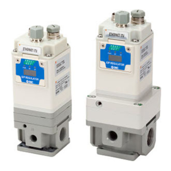
Electro-Pneumatic Regulator
PROFIBUS DP
ITV*0*0-RC**** Series
3
1
The intended use of the electro-pneumatic regulator is to control the flow
and pressure of fluid while connected to RS-232C communication.
1 Safety Instructions
These safety instructions are intended to prevent hazardous situations
and/or equipment damage. These instructions indicate the level of
potential hazard with the labels of "Caution," "Warning" or "Danger."
They are all important notes for safety and must be followed in addition
*1)
to International Standards (ISO/IEC)
, and other safety regulations.
*1)
ISO 4414: Pneumatic fluid power - General rules relating to systems.
ISO 4413: Hydraulic fluid power - General rules relating to systems.
IEC 60204-1: Safety of machinery - Electrical equipment of machines.
(Part 1: General requirements)
ISO 10218-1: Robots and robotic devices - Safety requirements for
industrial robots - Part 1: Robots.
Refer to product catalogue, Operation Manual and Handling
Precautions for SMC Products for additional information.
Keep this manual in a safe place for future reference.
Caution indicates a hazard with a low level of risk which, if
Caution
not avoided, could result in minor or moderate injury.
Warning indicates a hazard with a medium level of risk
Warning
which, if not avoided, could result in death or serious injury.
Danger indicates a hazard with a high level of risk which, if
Danger
not avoided, will result in death or serious injury.
Warning
Always ensure compliance with relevant safety laws and
standards.
All work must be carried out in a safe manner by a qualified person in
compliance with applicable national regulations.
This product is class A equipment intended for use in an industrial
environment. There may be potential difficulties in ensuring
electromagnetic compatibility in other environments due to conducted
or radiated disturbances.
Caution
Ensure that the air supply system is filtered to 5 microns.
Refer to the SMC website (URL:
https//www.smcworld.com)
information about Safety Instructions.
2 Specifications
2.1 General specifications
Model
ITV*010
ITV*030
Min. supply
(Set pressure) + 0.1 MPa
pressure
Max. supply
0.2 MPa
pressure
0.005 to
0.005 to
Set pressure range
0.1 MPa
0.5 MPa
Supply voltage
24 VDC ± 10%,
Current
0.12 A or less
consumption
10 bit / 10 bit
2
Input / output data
(data 1023 corresponds to 100% F.S.)
Linearity
±1% F.S. or less
Hysteresis
0.5% F.S. or less
Repeatability
±0.5% F.S. or less
Sensitivity
0.2% F.S. or less
Temperature
±0.12% F.S. / °C or less
characteristics
Ambient and fluid
0 to 50°C (no condensation)
temperature
Enclosure rating
Note 1) Excluding current consumption of communication line for PROFIBUS DP.
2.2 Size / Weight specifications
Model
ITV10*0
Size (mm)
50×50×109
Weight (no options)
320 g
2.3 Communication specifications
Item
Communication type
Master / Slave type
Synchronous type
Asynchronous type
Communication speed
Start bit
Data length
Stop bit
Parity bit
Flow control
Command end code
Character code
Warning
Special products (-X) might have specifications different from those
shown in this section. Contact SMC for specific drawings.
for more
3 Installation
3.1 Installation
ITV*050
ITV2090
(Set
Do not install the product unless the safety instructions have been read
pressure)
and understood.
This product is pre-set at the factory and must not be dismantled by
-13.3 kPa
the user. Contact your local SMC office for advice.
1.0 MPa
-101 kPa
Ensure, when installing this product, that it is kept clear of power lines
to avoid noise interference.
0.005 to
-1.3 to
Ensure that load surge protection is fitted when inductive loads are
0.9 MPa
-80 kPa
present (i.e. solenoid, relay etc.).
3.2 Environment
1)
Do not use in an environment where corrosive gases, chemicals, salt
water or steam are present.
Do not use in an explosive atmosphere.
Do not expose to direct sunlight. Use a suitable protective cover.
Do not install in a location subject to vibration or impact. Check the
product specifications.
Do not mount in a location exposed to radiant heat.
3.3 Piping
Before piping make sure to clean up chips, cutting oil, dust etc.
IP65
When installing piping or fittings, ensure sealant material does not
enter inside the port. When using seal tape, leave 1 thread exposed
on the end of the pipe/fitting.
Tighten fittings to the specified tightening torque.
ITV20*0
ITV30*0
3.4 Lubrication
50×50×131
66×66×152
420 g
720 g
Do not use a lubricator on the input side of this product. If lubrication
is required, place the lubricator on the 'output' side so that it does not
enter the product.
SMC products have been lubricated for life at manufacture, and do not
require lubrication in service.
Specification
If a lubricant is to be used in the system, refer to the catalogue for
details.
9,600 bps
4 Wiring
1 bit
8 bits
1 bit
Connect the cable to the connector on the main unit as shown in the
N/A
following diagram. Take precautions, as incorrect wiring will damage the
N/A
unit. Use a DC power supply capable of supplying the necessary power
CR • LF
requirements with minimal ripple.
ASCII
The 3 m straight cable specified refers to the power supply cable. The
communication cable should be ordered separately.
4.1 Power supply connector
Item
Connector for
power supply
4.2 Communication connector
Item
1
Connector for
communication
2
Note: Wire colours shown are when the optional cable is used.
S type: P398020-500-3, -502-3. L type: P398020-501-3, -503-3.
5 LED Display
Warning
Warning
6 Pressure Setting and Output Monitoring
Set Output Pressure
Caution
Command
Note) nn is limited to integral values from 0 to 1023.
Increase setting for output pressure
Caution
Command
Note) When set data nn is >= 1021, the value is set as nn=1023.
Decrease setting for output pressure
Command
Note) When set data nn is <= 2, the value is set as nn=0.
Request for set data
Caution
Command
Request of output pressure data
Command
Pressure setting can be done by sending input data using 10 bit as F.S.
to the electro-pneumatic regulator through the master PLC.
Pin assignment
Wire colour
1. +24V
Brown
4
1
2. N.C.
White
Output pressure
3. GND
Blue
2
3
Ex.) To set pressure at 0.3 MPa with ITV2030 (for 0.5 MPa type)
4. N.C.
Black
A pressure of 0.3 MPa is set by sending input data of "614" to the electro-
pneumatic regulator through the master PLC. Send "SET 614".
Pin assignment
Wire colour
1. N.C.
Brown
4
2. TxD
White
3
3. RxD
Blue
4. GND
Black
5
5. N.C.
Grey
Power supply
Communication
connector
connector
Communication LED
Power LED
Power LED
Communication LED
Status
Green LED ON
LED OFF
Waiting for Input
Green LED ON
Green LED ON
Receiving
Red LED ON
LED OFF
Waiting for Input / error
Red LED ON
Green LED ON
Receiving / error
Content
Response
Content
nn
0 to 1023
Set output
SET nn
pressure
Out of range
1023 < nn <= 9999
(0 - 1023)
Unknown command
Except 0 <= nn <= 9999
Content
Response
Content
Adds 2 to the set data
Indicates the
INC
mm
of output pressure
set data plus 2
Content
Response
Content
Subtracts 2 from the
Indicates the set
DEC
output pressure set
mm
data minus 2
data.
Content
Response
Content
Request for set
REQ
nn
Displays set data
data
Content
Response
Content
Request for output
Displays output
MON
nn
pressure data
pressure data
Set Data
0
1023
(a/F.S.) × 1023
0%×F.S. (=0)
100%×F.S.
a
(0.3 MPa / 0.5 MPa) × 1023 = 614
DEC
Pressure
100%
75%
50%
25%
0%
0
256
512
767 1023 (DEC)
Page 1 of 2
Input data
DEC
Advertisement

Related Manuals for SMC Networks ITV 0 Series


Summary of Contents for SMC Networks ITV 0 Series
- Page 1 ITV2-TF2Z358EN 2 Specifications 3 Installation 5 LED Display ORIGINAL INSTRUCTIONS 2.1 General specifications 3.1 Installation Power supply Communication Warning Model ITV*010 ITV*030 ITV*050 ITV2090 connector connector Instruction Manual (Set Do not install the product unless the safety instructions have been read Min.
- Page 2 ITV2-TF2Z358EN 7 How to Order Refer to the operation manual or catalogue on the SMC website (URL: http// www.smcworld.com) for How to order information. 8 Outline Dimensions Refer to the operation manual or catalogue on the SMC website (URL: http// www.smcworld.com) for outline dimensions.
Need help?
Do you have a question about the ITV 0 Series and is the answer not in the manual?
Questions and answers