Advertisement
Quick Links
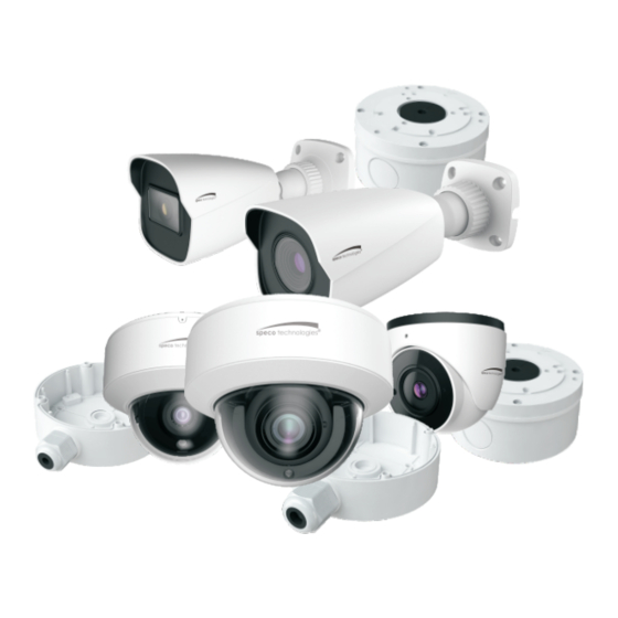
VLB5 /VLB6/VLD5/VLD6M/VLT7
User Manual
Thank you for purchasing our product. Speco Technologies is constantly developing and
improving products. We reserve the right to modify product design and specifications
without notice and without incurring any obligation.
Advertisement

Related Manuals for Speco VLT7


Summary of Contents for Speco VLT7
- Page 1 VLB5 /VLB6/VLD5/VLD6M/VLT7 User Manual Thank you for purchasing our product. Speco Technologies is constantly developing and improving products. We reserve the right to modify product design and specifications without notice and without incurring any obligation.
- Page 2 Warnings ■ If the product does not work properly, please contact the dealer or where the product was purchased. Speco Technologies is not responsible for any problems caused by improper operation or repair. ■ Do not expose the unit to heavy stress, violent vibration or long-term exposure to water and humidity during transportation, storage, and/or installation.
-
Page 3: Installation
● Backlight Compensation (BLC) When the back of the captured object is too much bright, you can set BLC for the captured object to make it clearer. Cables Video Output Video Switch Cable Power Cable Video Switch: Four video output modes can be optional--AHD, TVI, CVI and CVBS (a) remove the cover of the video switch cable;... - Page 4 2. Route and connect the cables . 3. Secure the mounting base with camera to the wall with screws as shown below. Rubber plug VLB6 VLB5 4. Bracket adjustment. Before adjustment, preview the image of the camera on a monitor and then loosen the fixed ring to adjust the view angle of the camera.
- Page 5 90.2mm 74.3 (mm) ∅4.6 90.2mm 74.3 VLD5 VLD6M 2. Rotate the trim ring anticlockwise to remove it from the camera. 3. Loosen the screws to open the lower dome. Then route and connect the cables. 4. Secure the camera to the wall with screws provided as shown below. Trim ring Rubber plug * Install it when routing the...
- Page 6 6. Install the lower dome back to the camera and fix it with screws. Then put the trim ring onto the lower dome and then rotate it clockwise until it is locked. Finally, remove the protection film softly. Trim ring ● Mounting for VLT7 1. Loosen the set screw to disassemble the camera. Set Screw Mounting Base...
- Page 7 (mm) 44.2 Ø91.6 38.2 Ø51.0 Ø4.5 Install the camera unit and enclosure to the mounting base and then adjust the dome to obtain an optimum view angle. Pan: 360° Tilt: 75° 5. Finally, secure the camera with the set screw.
-
Page 8: Specifications
Specifications Models VLB5 VLB6 VLD5 VLD6M VLT7 Specifications Camera Image Sensor 1/2.9" CM S Resolution Image size 1920×1080 Video Output AHD/TVI/CVI/CVBS (*camera comes defaulted to HD-TVI) Image System PAL/NTSC Electronic Shutter Auto; 1/50s~1/100000s(PAL);1/60s~1/100000s (NTSC) IR Distance (feet) 65.6~98.4 98.4 ~164.0 32.8~65.6... - Page 9 Model: VLB5 /VLB6/VLD5/VLD6M/VLT7 Federal Communications Commission (FCC) Statements This device complies with Part 15 of the FCC Rules. Operation is subject to the following two conditions: (1) This device may not cause harmful interference, and (2) This device must accept any interference received, including interference that may cause undesired operation.
Need help?
Do you have a question about the VLT7 and is the answer not in the manual?
Questions and answers