Advertisement
Quick Links
Advertisement

Subscribe to Our Youtube Channel
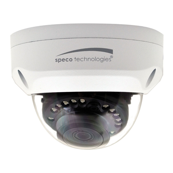
Summary of Contents for Speco VLD2A
- Page 1 User Manual Multi Format HD Analog Dome Camera VLD2A Version 1.0.2...
- Page 2 Welcome Thank you for purchasing our Multi Format HD Analog Dome camera! This user manual is designed to be a reference tool for your system. Please read the following safeguard and warnings carefully before you use this series product! Please keep this user’s manual well for future reference! Important Safeguards and Warnings 1.Electrical safety All installation and operation here should conform to your local electrical...
- Page 3 Please do not allow rain or damp to the indoor device in case fire or lightning may occur. Please keep the sound ventilation in case of heat accumulation. Please pack the device with standard factory packaging or material with same quality when transporting the device.
- Page 4 Please contact the Speco Technologies Technical Support if there are any problems when using the device. Please contact Customer service for the latest procedure and supplementary documentation. Speco Technologies is not liable for any loss caused by the operation which is not followed by the manual.
-
Page 5: Table Of Contents
Table of Contents 1 General Introduction ............... 1 Overview ................. 1 1.2 Features ................1 2 Device Framework ..............2 3 Installation ................4... -
Page 6: General Introduction
General Introduction 1.1 Overview This series HDTVI camera conforms to the HDTVI standard. It supports video signal high-speed long distance transmission without any delay. 1.2 Features High-performance CMOS image sensor, megapixel definition. Support HD video, control signal coaxial transmission. ... -
Page 7: Device Framework
2 Device Framework See Figure 2-1 for the dimension. Figure 2-1 The device ports include one DC12V power input port, one BNC video output port and one DIP switch. Please refer to Figure 2-2 for DC12V power input port. Figure 2-2 Please refer to Figure 2-3 for video output port. - Page 8 Note It is ON and OFF when the DIP switch is moved upward and downward respectively. Please refer to Table 2-1 for more details about DIP switch. Switch 1 Switch 2 Output Mode CVBS Table 2-1...
-
Page 9: Installation
Installation Important Before the installation, please make sure the installation surface can sustain at least 3X weight of the bracket and the camera. Figure 3-1 Step 1 Use wrench to loosen three fixing screws on the enclosure and remove the dome cover. - Page 10 Use tools to put the expansion bolts into the installation holes and fix them firmly. Step 4 Adjust the location of the device installation pedestal; pull the cable through the hole on the installation surface. Align the bolt fixing holes of the device pedestal with the expansion bolt fixing holes on the installation surface;...
- Page 11 Note This manual is for reference only. Slight difference may be found in the user interface. All the designs and software here are subject to change without prior written notice. All trademarks and registered trademarks mentioned are the properties of their respective owners.


Need help?
Do you have a question about the VLD2A and is the answer not in the manual?
Questions and answers