Table of Contents
Advertisement
USE AND MAINTENANCE INSTRUCTION MANUAL
LAWN MOWER BRUSH CUTTER / LAWN MOWER FOR EDGES
Series:
Models:
BT 60
Revision
Date
1
01/10/2014
0
25/05/2010
DCS‐BT
60‐60 Traction/ 60 Swing Top
DCS 60
Original Instructions
Translation of the original instructions (for other languages)
Description
REVISION
ISSUE
Via Copernico, 85 – 47122 Forlì (FC) ITALY
Tel. +39 (0)543 774 314 ‐ Fax +39 (0)543 778 658
web: http://www.ecotechitalia.com
E‐mail : info@ecotechitalia.com
DCS 60 Traction
DCS 60 Swing Top
Advertisement
Table of Contents

Subscribe to Our Youtube Channel
Related Manuals for Ecotech Italia DCS-BT Series

Summary of Contents for Ecotech Italia DCS-BT Series
- Page 1 Via Copernico, 85 – 47122 Forlì (FC) ITALY Tel. +39 (0)543 774 314 ‐ Fax +39 (0)543 778 658 web: http://www.ecotechitalia.com E‐mail : info@ecotechitalia.com USE AND MAINTENANCE INSTRUCTION MANUAL LAWN MOWER BRUSH CUTTER / LAWN MOWER FOR EDGES DCS‐BT Series: 60‐60 Traction/ 60 Swing Top Models: BT 60 DCS 60 DCS 60 Traction DCS 60 Swing Top Original Instructions Translation of the original instructions (for other languages) Revision Date Description ...
-
Page 2: Table Of Contents
TABLE OF CONTENTS 1 PREMISE .............................................. 3 1.1 General Information ........................................ 3 1.2 Intended Users .......................................... 3 1.2.1 User Qualifications ........................................ 3 1.2.2 Symbols ............................................ 3 2 GENERAL INFORMATION .......................................... 5 2.1 Manufacturer Identification Information .................................. 5 2.2 Machine identification rating plates and data: ................................ 5 2.3 Declarations ........................................... 5 2.3.1 Declaration of Conformity ...................................... 5 2.4 Safety Regulations ......................................... 6 2.5 Guarantee ............................................ 6 2.6 At the expense of the client ...................................... 6 3 DESCRIPTION OF THE MACHINE ....................................... 6 3.1 Operational Principle ........................................ 8 3.1.1 Intended Use .......................................... 8 ... -
Page 3: Premise
PREMISE IMPORTANT! This machine has been manufactured in compliance with the Machine Directive 2006/42/EC and is certified with the mark. BEFORE PERFORMING ANY OPERATIONS ON THE MACHINE, THE ASSIGNED OPERATORS AND TECHNICIANS MUST CAREFULLY READ THE INSTRUCTIONS CONTAINED IN THIS PUBLICATION (AND IN THOSE ATTACHED) AND FOLLOW THEM DURING THE EXECUTION OF THE PROCEDURES. IN CASE OF DOUBTS ON THE PROPER INTERPRETATION OF THE INSTRUCTIONS, CONTACT THE CLOSEST SUPPORT CENTRE. GENERAL INFORMATION This Manual has been divided into independent chapters, each of which is aimed at a specific operator role (OPERATOR/USER, MAINTENANCE MECHANIC), for which the competencies necessary to operate the machine safely have been defined. The chapter sequence corresponds to the temporal logic of the service life of the machine. To facilitate rapid comprehension of the text, certain terms and abbreviations are used, the meanings of which are indicated in the tables following Paragraph 1.2.2 Symbols and Paragraph 9.3 GLOSSARY. Below, the meanings of the symbols are described for: The different levels of danger in the “Use and Maintenance” operations on the machine; The operator qualifications; Safety, as applied directly to the machine. The use of these symbols enables the information necessary for the proper and safe use of the machine to be provided quickly and unambiguously. INTENDED USERS ... - Page 4 NOTE Important information or procedure. Table 1‐1: Symbols concerning information and/or procedures 1.2.2.2 Symbols concerning operator qualifications Symbol Description Generic worker: operator with no specific skills, capable of carrying out simple tasks when instructed to do so by qualified technicians. Hoist and handling equipment operator: operator qualified for the use of equipment or vehicles for hoisting and handling materials and machines (carefully following the instructions of the manufacturer, in compliance with the laws in force in the country where the machine is being used. Maintenance Mechanic: qualified technician capable of operating the machine under normal conditions, of operating it using the sustained‐action controls (JOG) with the protective devices deactivated and of intervening upon the mechanical components for adjustment operations, maintenance procedures, as well as for any necessary repairs. Usually, this technician is not qualified to perform procedures on live electrical systems. Maintenance Electrician: qualified technician capable of operating the machine under normal conditions, of operating it using the sustained‐action controls (JOG) with the protective devices deactivated and is assigned to all procedures involving the electrical system, including adjustment, maintenance and repair. This technician is qualified to perform procedures on live electrical systems inside of the cabinets and junction boxes. Manufacturer Technician: This qualified technician is made available by the manufacturer to perform complex operations in particular situations, or, in any case when agreed to with the end user. This technician's expertise, depending on the case, may be mechanical and/or electrical and/or electronic and/or software. Table 1‐2: Symbols concerning operator qualifications 1.2.2.3 Symbols concerning safety Symbols surrounded by a triangle indicate danger Symbol Name: It would be best to read this manual thoroughly before starting up the machine and operating it. ...
-
Page 5: General Information
GENERAL INFORMATION MANUFACTURER IDENTIFICATION INFORMATION ECOTECH ITALIA s.r.l. Via Copernico 85 – 47122 Forlì (FC) ‐ Italy Tel. 0039 (0)543 774314 Fax. 0039 (0)543 778658 E‐mail. info@ecotechitalia.com AFTER SALES SERVICE/SPARES: found at Resellers or Authorised Service Centres: see the list on www.ecotechitalia.com. MACHINE IDENTIFICATION RATING PLATES AND DATA: Each machine is identified by a CE plate on which information concerning the machine has been printed indelibly. For any communication with the manufacturer or the service centres always cite the following references: Figure 2‐1 CE plates The location of the plate may vary from machine to machine. DECLARATIONS The machine has been manufactured in conformity with the European Community Directives pertinent and applicable at the moment of its release on the market. ... -
Page 6: Safety Regulations
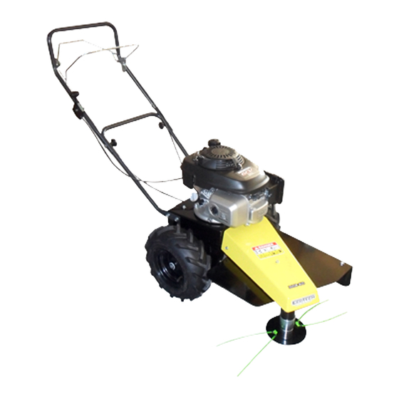
SAFETY REGULATIONS The machine has been manufactured taking into account the provisions found in the technical safety standards listed below: UNI EN ISO 12100‐1. Safety Of Machinery ‐ Basic Concepts, General Principles For Design ‐ (Part 1 Basic Terminology, Methodology) UNI EN ISO 12100‐2. Safety Of Machinery ‐ Basic Concepts, General Principles For Design ‐ (Part 2 Technical principles) UNI EN ISO 14121‐1. Machine Safety – Risk assessment principles UNI EN ISO 13857 Machine Safety ‐ Safety Distances to keep upper and lower extremities away from reaching dangerous areas. UNI EN 349 Machine Safety ‐ Minimum Safety Distances to avoid crushing parts of the body UNI EN ISO 3744 Acoustics – Determination of the sound levels from sources of noise by way of the measurement of sound pressure UNI EN ISO 20643 Mechanical Vibration ‐ Portable Machines and those manually operated ‐ Principles for the assessment of the emissions of vibrations. Table 2‐2: Safety Regulations GUARANTEE ... - Page 7 DCS 60 ‐ Traction ‐ Swing Top 1 STARTER 2 AIR FILTER 3 FUEL TANK CAP 4 STARTER LEVER 5 THROTTLE LEVER 6 CUTTER ENGAGEMENT LEVER 7 CUTTING ADJUSTMENT 8 OIL FILLER CAP 9 ANGLE CONTROL SWITCH Figure 3‐2: Details DCS 60 1 STARTER 2 AIR FILTER 3 FUEL TANK CAP 4 STARTER LEVER 5 FORWARD MOVEMENT ADJUSTMENT 6 THROTTLE LEVER 7 CUTTER ENGAGEMENT LEVER 8 FORWARD MOVEMENT ENGAGEMENT LEVER 9 CUTTING ADJUSTMENT ...
-
Page 8: Operational Principle
1 STARTER 2 AIR FILTER 3 FUEL TANK CAP 4 STARTER LEVER 5 FORWARD MOVEMENT ADJUSTMENT 6 THROTTLE LEVER 7 CUTTER ENGAGEMENT LEVER 8 FORWARD MOVEMENT ENGAGEMENT LEVER 9 CUTTING ADJUSTMENT 10 OIL FILLER CAP 11 PARKING BRAKE 12 SLOPE ADJUSTMENT LEVER 13 SPEED CHANGER CONTROL LEVER Figure 3‐4: Details DCS 60 Swing Top OPERATIONAL PRINCIPLE 3.1.1 Intended Use The lawn mower brush cutter you have purchased was designed and manufactured for cutting grass/brambles/brush on uncultivated ground and underbrush, particularly suitable for finishing and cutting in land with the presence of debris. The 60 versions were designed and manufactured to operate on level ground with a maximum slope of 15°, whilst the 60 Swing Top versions were designed to work on a slope of up to 45°, always maintaining the motor aligned along the horizontal (0°). The technical performance indicated in this manual refers exclusively to new products or those maintained efficient, following ... -
Page 9: Vibrations
VIBRATIONS Operational Conditions: Motor RPM during tests 3000 rpm. DCS BT 60 Traction‐Swing Top X 1.6 m/s² AEQ Y 2.2 m/s² Z 4.1 m/s² NOISE EMISSIONS The weighted equivalent continuous sound pressure level A in the work station is: DCS BT 60 Traction‐Swing Top 93 dB (A) Other phonometric measurements in the workplace must be performed pursuant to what is provided for in the standards in force in the country of use. TECHNICAL SPECIFICATIONS BT 60 DCS 60 DCS 60 Traction DCS 60 Swing Top Motor Honda GCV 160 Honda GCV 190 Honda GXV 160 Start up Recoil pull starter Transmission Belt and mechanical ‐ ‐ Belt and mechanical Belt and mechanical with variable speed control ... -
Page 10: Storage
STORAGE During long periods of storage of the machine it would be best to: Empty the fuel tank of fuel; Lubricate the cylinder with a suitable product, available at your reseller; Clean the air filter; Empty any residual gasoline from the carburettor; Grease any parts with the paint worn off by wear or impact of the machine and any parts where the treatment has worn off to avoid possible rust formation. PRELIMINARY CHECKS Check that all of the safety instruction adhesive labels are in order and legible. Check that the machine is cleaned of plant residue and debris. Check that all of the safety guards and grilles are in order and in good condition Before starting the motor Visually inspect for any leaks and/or defective, missing or worn parts. See to any necessary repairs before using the machine again. ... -
Page 11: Scrapping
SCRAPPING Proceed with the disassembly of the machine dividing its parts based on the materials with which they were manufactured. Follow the waste management and disposal standards in force. SAFETY GENERAL WARNINGS Inside of this manual and on the machine there are indications and printed messages together with the danger symbol shown below that indicate potential hazard. It would be best, therefore to pay close attention to what is shown or written in order to ensure greater safety for the operator and anyone else who might be in the operational range of the machine. Read this manual before using the machine. Only the instructions found in this manual will assist you in using the machine safely and efficiently. Safe usage is only the result of proper operation of the machine, in compliance with the standards and limitations described in this manual. Therefore, you must know and comply with all safety warnings in this manual and those relative to the proper operation of the machine. USE RESTRICTIONS ... -
Page 12: Signs
SIGNS See Table 1‐3: Symbols concerning safety for the meaning of the symbols. ON TOP OF THE MACHINE THIS FIGURE IS FOUND: Figure 5‐2: Adhesive label located on the machine ATTENTION!!! This machine is equipped with sharp cutting components; therefore keep hands and feet a safe distance away from these. Never perform any procedures on the machine whilst it is running. It is recommended to not work in areas with gravel, rocks and/or foreign objects on the ground that may be projected by the cutting blades making it extremely dangerous for persons or things in the vicinity of the running machine. Keep all personnel at least 15 metres away from the machine. The operator shall always wear a protective face mask and as necessary rubber boots as well. ATTENTION!!! Always keep the hands at a safe distance from the oscillating mechanism on the machine as it can easily crush the fingers. APPLICATION OF THESE REGULATIONS IS NOT A WASTE OF TIME! THESE REGULATIONS CONTRIBUTE TO KEEPING PERSONS AND THINGS FROM IRREPARABLE HARM AND ENSURE OPERATOR SAFETY. RESIDUAL RISKS Noise: always wear ear protection. It is recommended that one take regular breaks during work time. Do not use the machine for more than 8 hours in a day. MACHINE USE Dear customer, we thank you for the trust you have given ECOTECH ITALIA. We are confident that use of this new machine will fully fulfil your requirements. For the purpose of obtaining optimum application and efficient maintenance of the machine over time, please read all of the directions and warnings described in this booklet, which must always be kept together with the machine. BEFORE STARTING UP THE MACHINE READ THE USE INSTRUCTION MANUAL THOROUGHLY! ... -
Page 13: Operational Modes
Speed Set speed 1.3 Km/h N/A Set speed 1.3 Km/h Set the speed changer control lever on the left (Figure 3‐24 n. 13) to increase or reduce the speed Steering Use sufficient pressure on the hand grips to turn right or left. Slope N/A N/A The machine enables three inclination angles to the right and three to the left. To adjust the inclination angles use the red left hand lever (Figure 3‐2 no. 4) then adjust the correspondent pins in one of the seven angle adjustment holes (no. 15) Motor Refer to the motor instruction manual. Table 6‐1: Adjustments OPERATIONAL MODES 6.2.1 WORKING ON LEVEL GROUND After having performed the preliminary checks referred to in point 4.3 and after starting the motor, activate the blade coupling lever (Figure 6‐3– no. 2), select the gear in which you want to work (depending on the models), engage the forward movement lever (Figure 6‐3– no. 3) and begin work using the greatest care at all times. ... -
Page 14: Normal Stop
Always start the work at the bottom of the slope advancing sideways and on parallel tracks upwards to ensure better discharge of the cut grass downwards. It is recommended that one work first on level ground or with a very slight slope so as to familiarise one's self with the machine’s operation. Steep slopes should be worked on only by very experienced operators. The machine has been designed to work on slopes transversally and not in perpendicular. THE MANUFACTURER WILL NOT BE LIABLE FOR ANY DAMAGE CAUSED BY THE MOTOR SEIZING DUE TO INAPPROPRIATE USE OF THE MACHINE. NORMAL STOP Once the work has been completed, to stop the motor, put the gas lever on the (Figure 3‐2 no. 6) STOP position and (or if the motor is equipped use the stop switch ... -
Page 15: Extraordinary Maintenance
EXTRAORDINARY MAINTENANCE Ask the reseller to perform these operations that require specific capabilities and equipment. Component to be Every 100 hours / Inspection Every 10 hours Every 50 hours checked year Check belt tension Cutting head belt Check belt wear Replace as necessary. Forward movement Check that the machine does not move engagement lever forward with the lever in neutral Brake Check efficiency of the brake Frame Check for rust and/or cracks Check that they are in their proper place Safety warnings ... -
Page 16: Spares And Accessories
C. The blades, when the lever is disengaged, continue to rotate: Check that the brake pulley is engaged If this is not the case loosen the cutting adjustment lever until the brake lining rests against the shoulder of the pulley. Check that the brake lining is not worn D. The machine does not operate properly: check: That the wire is not too worn out. If it did replace it as follows: turn off the engine, remove the old wire, take a new one and give him a simple knot in the middle (Figure 7‐ 2), and finally fits into its housing; That the air filter (no. 13) is not too fouled causing a notable loss in power of the motor. In this case blow it out with compressed air or replace it with a new one, which may be purchased at your reseller. That the gas has not nearly run out. That the oil level is not lower than the minimum level (no. 11) Figure 7‐2: Wire replacement That the belt does not slip: in this case adjust the wire. With the forward movement lever engaged, the machine does not move: ... -
Page 17: Glossary
The ECOTECH ITALIA Company is considered released from any liability in the case that the machine is used improperly, such as for example: Improper use of the machine or operation by untrained/unqualified personnel; Use in contrast with specific standards and legislation; Fuel supply defects; Serious deficiencies in maintenance; Unauthorised modifications or service procedures; Use of non original spare parts or ones not specifically for the model of the machine Total or partial lack of compliance with the instructions; Extraordinary events. CONSERVATION OF THE INSTRUCTION MANUAL This instruction manual is to be conserved carefully and shall accompany the machine in every change of hands that the machine might undertake during its service life. ... - Page 18 OPERATOR QUALIFICATION: Minimum competence level that the operator must possess to carry out the operations described; NUMBER OF OPERATORS: The number of operators necessary for the proper carrying out of the operations described and arising from a careful analysis undertaken by the manufacturer, because of which an end user using a different number of personnel could inhibit the achievement of the intended result or place the personnel involved in jeopardy. MACHINE STATUS: The machine status includes the operational mode: for example, automatic running, stop, etc., the safety conditions on the machine such as guards included, guards excluded, emergency stop button pressed, type of insulation from energy sources, etc.; RESIDUAL RISK: Risks that remain, regardless of the fact that safety measures have been integrated into the design of the machine and of the complementary safety measures and guards adopted; SAFETY COMPONENTS: Component intended for the performance of a safety function the breakage and/or malfunction of which could create a danger for the safety of personnel. ...
Need help?
Do you have a question about the DCS-BT Series and is the answer not in the manual?
Questions and answers