
Related Manuals for GAI-Tronics Commander GSM


Summary of Contents for GAI-Tronics Commander GSM
- Page 1 Commander GSM installation and operation guide GAI-Tronics with...
-
Page 3: Table Of Contents
Contents Introduction Welcome Keypad options Installation Important notes for installers Mounting the enclosure Preparing the enclosure Pole mounting Wall mounting Desk mounting Internal battery positioning SIM insertion and connections Testing the wireless module Operating states of the phone To switch on Indicator power saving To switch off To switch on and test... -
Page 4: Introduction
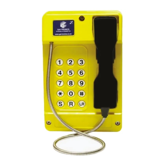
The handset is toughened and features a stainless steel connection cable. All fixing points for the Commander GSM are concealed internally to ensure environmental sealing and also to deter damage or removal due to vandalism. -
Page 5: Keypad Options
Keypad options The Commander GSM range is available with full numeric keypads for manual dialling; with auto-dial buttons for dialling pre-stored numbers from a single button press; or a combination of both. Alternatively a blank panel can be specified, whereupon the Commander GSM is programmed to auto-dial a single number as soon as the handset is lifted. -
Page 6: Installation
DC power adapter The DC power adapter supplied as standard with the Commander GSM telephone is for in-building use only. Where the IP65 capabilities of the Commander GSM telephone are to be employed by installing the telephone outside, and subject to... -
Page 7: Mounting The Enclosure
Mounting the enclosure This section covers the three main ways in which the Commander GSM enclosure can be positioned: • Pole mounted - see page 6 • Wall mounted - see page 8 • Desk mounted - see page 9 Preparing the enclosure Before mounting the Commander GSM, check the cable routing and require- ments. Fit the appropriate gland to the case as follows: 1 Remove the RED blanking plug, leaving the other (usually BLACK) in place. -
Page 8: Pole Mounting
Note: Banding straps (large scale worm-drive clamps) are not included in this kit and must be obtained separately. For details of where banding can be obtained, please refer to GAI-Tronics. 1 Use a 5mm hex key to remove the three bolts that secure the front section of the enclosure to the rear section. - Page 9 4 Ensure that the cable glands of the rear casing are facing downwards. Pass the first banding strap around the pole and also around the upper mounting clamp. Move the rear casing, upper clamp and strap assembly up or down the pole until it is at the correct height and then tighten the strap until it holds tight. 5 Pass the second banding strap around the pole and also around the lower mounting clamp.
-
Page 10: Wall Mounting
Wall mounting 1 Use a 5mm hex key to remove the three bolts that secure the front section of the enclosure to the rear section. Carefully separate the two sections. 2 If fitted, remove the four rubber feet from the mounting holes of the rear casing. 3 Mount the rear half of the moulded enclosure on a suitable vertical surface, (with screws/bolts suitable for the surface material) using the four 7mm diam- eter pre-drilled holes shown (ensure that the cable glands of the rear casing... -
Page 11: Desk Mounting
Desk mounting When mounting on horizontal surfaces (greater than 150 x 280mm) use this method to provide a ‘rake’ for convenient operation and to ensure that the cable entries are located at the rear. 1 Use a 5mm hex key to remove the three bolts that secure the front section of the enclosure to the rear section. -
Page 12: Internal Battery Positioning
Ensure correct polarity as shown. Wall and pole mounting The Commander GSM is supplied as standard with its internal batteries in the correct position for wall and pole mounting, as shown below. No adjustment is required to their position within the enclosure. - Page 13 2 Move the battery assembly to the other side of the rear casing and re-insert the four screws (two of the screws will use different mounting holes in the battery pack assembly). 3 Ensure that all battery connections are correct and secure. Important Safety Information • Only replace batteries with the correct type: Cyclon 2.5Ah sealed lead-acid D cell, GAI-Tronics part no 983-02-00054-000. Replace both batteries as a pair. • Only replace fuse with the correct type: 2A(T) soldered axial fuse, GAI-Tronics part no 043-02-0340-002. • Ensure correct polarity as shown.
-
Page 14: Sim Insertion And Connections
SIM insertion and connections This section covers the internal connections and preparations necessary for operation. 1 If the front casing is still in place, use a 5mm hex key to remove the three bolts that secure the front section of the enclosure to the rear section. Carefully separate the two sections. - Page 15 4 Connect the supplied stub antenna to the coaxial (SMA type) connector at the base of the main circuit board and secure it with the plastic clip. Stub antenna Antenna clip Alternatively, if low signal strength demands the use of an external antenna, use the second gland entry, fitted with an appropriate sized gland, to bring the antenna cable into the enclosure and attach it to the coaxial connector on the circuit board.
- Page 16 8 Feed the DC supply cable through the cable gland nut and gland body at the base of the rear casing. Once sufficient cable is within the casing, tighten the gland nut sufficiently to clamp the cable to make a seal. 9 Once the power cable is within the enclosure, attach the supplied green two- pin plug onto the conductors as shown below and tighten the two screws.
- Page 17 11 Double check that all internal connections are correct: Handset hook connections Handset audio connections Ringer connection Internal battery port connection CHARGE FUNCTION ERROR DC power in connection 12 Once all connections have been checked, the phone should be ready for initial switch on and testing. Please see the ‘Testing’ section on the next page.
-
Page 18: Testing The Wireless Module
Testing the wireless module Located at the base of the main circuit board are three indicators that provide useful status information: CHARGE FUNCTION ERROR On/off button CHARGE FUNCTION ERROR The indicator functions are as follows: • CHARGE - On, whenever external power is first applied. • FUNCTION - Indicates the current operation. See the table below. • ERROR - Indicates problems with operation. -
Page 19: Operating States Of The Phone
Operating states of the phone • On - The phone is fully powered and ready to make and receive calls. • Charge only - This is the state that the phone will enter when external DC power is applied. If power is removed, the phone will enter the “Off” state. • Off - This is the state in which the phone is shipped from the factory. -
Page 20: To Switch On And Test
The following section assumes the Installer has access to another mobile phone capable of sending and receiving SMS text messages. These messages are used to send Test and Configuration commands to the Commander GSM phone. Alternatively the USB connection can be used. Please see Appendix A. -
Page 21: Further Configuration
Further configuration • For many installations, the steps outlined so far will result in a fully functioning phone and you can proceed directly to the Operation section on the next page. • However, the Commander GSM is also highly customisable for many situations. Detailed configuration is made possible by either sending specially formatted SMS messages from another phone or by connecting a computer via the USB port. -
Page 22: Operation
Operation In operation, the Commander GSM operates in exactly the same manner as any hard-wired tough phone. To make a call 1 Lift the handset and wait for the dial tone. Note: With the zero button keypad option lifting the handset out of the cradle will automatically dial a pre-determined number. -
Page 23: Support And Aftercare
Support and aftercare The purchase of your GAI-Tronics product does not end our commitment to you. In addition to our warranty obligations, GAI-Tronics are able to offer various levels of maintenance packages, installation and commissioning packages and technical support, from ad-hoc repairs to full maintenance contracts. -
Page 24: Troubleshooting
MUST ONLY be replaced with the correct in line fuse assembly from GAI-Tronics Ltd. ERROR light is permanently ON a Check the SIM card has been installed and has been installed correctly, see section ‘SIM insertion and connections’. - Page 25 ERROR light flashing Long/Fast a This indicates a weak GSM signal. b If the unit has responded to the 1234stat0 SMS command, then compare the results of the reported signal (please see section ‘To switch on and Test’ on page 16) with the table below. c If the unit is not responding to the 1234stat0 SMS command connect a laptop or similar computer to the internal USB port.
-
Page 26: Important Safety Information
Important safety information IMPORTANT! This phone, like any wireless phone, operates using radio signals and the wireless network, as well as user-programmed functions, which cannot guarantee connection in all conditions. Therefore, you should never rely solely upon any wireless phone for essential communications (e.g. medical emergen- cies). Remember, to make or receive any calls, the phone must be switched on and in an area with adequate cellular signal strength. Emergency calls may not be possible on all wireless phone networks or when certain network services or phone features are in use. - Page 27 Other medical devices Operation of any radio transmitting equipment, including the phone, may interfere with the function of inadequately protected medical devices. Consult a physician or the manufacturer of the medical device to determine if they are adequately shielded from external RF energy or if you have any questions. Switch off your phone in health care facilities when any regulations posted in these areas instruct you to do so.
-
Page 28: Appendices
Appendices Appendix A - Using configuration commands The Commander GSM has numerous features that can be configured using com- mands that you send to it either via SMS messages from another phone or by a computer connected to the internal USB port. Most commands entered via the USB port are also accepted while the phone is in charge only mode, i.e. -
Page 29: Sending Commands Via Usb Port
Sending commands via USB port IMPORTANT: Before connecting the Commander GSM to a computer via USB, ensure the USB device driver software has been downloaded from www.burnsidetelecom.com, downloads section link and installed on the computer. Configure Hyperterm or similar USB communicator to connect to the virtual COM port assigned to the USB driver. -
Page 30: List Of Commands (For Use With Sms And Usb)
List of commands (for use with SMS and USB) Returns the status of the phone. If n is omitted, it is interpreted as STATn zero. n ð 0 for general status, useful during installation: State: s (phone state, see table below) Signal: -89dBm Supply: 12.2V Bat: 4.191V Temperature – (in degrees Celsius) Now: 20 Min: 18 Max: 26 No fault/Fault... - Page 31 CLRTEMP Clears the maximum and minimum temperature memories (as a result, they will initially show the current actual temperature). CFGn=x Read and write configuration setting. n ð 0 My number sending. Determines whether the phone number is declared to the destination being called: x ð 0 Use the setting defined by the network (default). x ð...
- Page 32 CFGn=x (continued) n ð 8 Call progress announcement mode. Instead of tones, voice announcements may be played to suit the particular condition of the phone. For example “We are unable to connect your call, please try again later”. Note: This feature is an additional option. It must be specified at the time of ordering.
- Page 33 CFGn=x (continued) n ð 19 Earpiece level. The output level may be increased in four steps of 3dB. Normal level (default). x ð 0 x ð 1 +3dB. x ð 2 +6dB. x ð 3 +9dB. x ð 4 +12dB. n ð...
- Page 34 AUTOn (where here n is the phone number), for example: 1234auto07773450543 Memory Location n=11: This is the location for storing the special phone number used with the GAI-Tronics/Burnside System Management Application. The application and supported features are an additional option and not detailed here. For further information contact your supplier.
-
Page 35: Appendix B - Technical Specifications
Appendix B - Technical Specifications Operational Requirements • GSM network coverage. The P400 provides Quad-Band Global cellular con- nectivity and is designed to work in public and private mobile networks. All that is required is an appropriate SIM card, which should be sourced separately. Not suitable for • Payphone extensions • Public Emergency Telephone System (PETS) Product features Power supply... -
Page 36: Appendix C - Compliance To Standards
Appendix C - Compliance to standards European Directive 1999/5/EC – European Radio & Telecommunications Terminal Equipment Directive. Information Technology and Generic Standards for commercial and heavy industrial environments Emissions: EN 50121-4:2006 Radiated disturbance CISPR 11:2003, Class A (referencing EN 61000-6-4:2001) Continuous disturbance EN 61000-6-4:2007 EN 55022:2006 inc A1:2007... - Page 37 Documentation by: www.ctxd.com Part number: 502-20-0142-001 Iss. 2d Jan 2012...
- Page 38 Fax: +44 (0)1283 500400 www.gai-tronics.co.uk Burnside Telecom Limited Opus House, Manor Court Herriard, Basingstoke Hampshire, RG25 2PH, United Kingdom Tel: +44 (0)3333 441200 www.burnsidetelecom.com The policy of GAI-Tronics and Burnside Telecom is one of continuous improvement, therefore the parties reserve the right to change specification without notice.
Need help?
Do you have a question about the Commander GSM and is the answer not in the manual?
Questions and answers