
Related Manuals for GAI-Tronics Auteldac 4


Summary of Contents for GAI-Tronics Auteldac 4
- Page 1 Installation and User Guide Auteldac 4 ATEX / IEC Ex Approved Hazardous Area Telephone GAI-TRONICS A Division of Hubbell Ltd...
-
Page 2: Table Of Contents
2.10 Possible Operating Faults ...........21 OPERATION ...............22 Making and Receiving Calls ..........23 Last Number Redial.............23 Recall Function..............23 Programming...............23 Secrecy or Mute Function ...........23 Headset Operation ..............24 MAINTENANCE ..............25 Procedures ................25 Fault Finding & Field Repairs ..........25 CE DECLARATION.............26 Auteldac 4... -
Page 3: Product Description
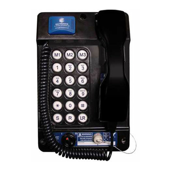
COMPONENTS OF THIS TELEPHONE WHILST UNPACKING, PREPARING AND INSTALLING IT IN INCLEMENT WEATHER CONDITIONS OR BY NEGLIGENCE. FAILURE TO CARRY OUT THIS PRECAUTION WILL INVALIDATE CERTIFICATION AND YOUR WARRANTY PRODUCT DESCRIPTION Figure 1 – Auteldac 4 Hazardous Area Telephone at a glance Auteldac 4... -
Page 4: At A Glance
1.1 At a Glance Auteldac 4 is an Ex certified telephone built to withstand arduous industrial atmospheres and environmental extremes. Features include: Carbon loaded glass filled polyester body - rugged and corrosion • free. ATEX / IEC Ex certified for safe operation in hazardous areas •... -
Page 5: Dimensions
• Vertical separation between centres: 270.0mm. The lower pair are about 10mm up from the bottom edge of the unit. Handset cord lengths: Standard curled cord: 320mm extending to 1m. Standard stainless steel cord: 755mm Other cord lengths are available as special options: contact GAI-Tronics for details. Auteldac 4... -
Page 6: Related Standards And Regulations
ITU-T recommendation K.21 (10/2000) - Enhanced surge protection. 1.4.4 Telephony Testing to: I-CTR37 & CTR38 pan-European ETSI telephony standards. The Auteldac 4 has been designed for pan-European single terminal connection to the Public Switched telephone Network (PSTN). However, due to differences between the individual PSTNs &... - Page 7 The GAI-Tronics Quality Management System has been approved by LRQA to ISO9001-2000. Certificate No. 861888 1.4.8 IEC Ex Certification Auteldac 4 complies with the following IEC standards: IEC 60079-0: 2007-10 Explosive atmospheres - Part 0: Equipment - Edition: 5 General requirements...
-
Page 8: Headset
6 metres away from the telephone unit. Note: Refer to section 2.2.1 for hazard warnings regarding long corded Headsets & handsets. 1.5 Suitability for Use Auteldac 4 telephones are suitable for connection to the following types of telephone line: Direct analogue PSTN •... -
Page 9: Environmental Considerations
Telephone enclosure IP Rating: IP66 (curly cord variants) • IP55 (steel cord variants) (NB the handset is excluded from this rating) The Auteldac 4 has not been certified for installation or operation in • explosive dust atmospheres. High pressure hoses should not be used on this product. -
Page 10: Protection Against Hazards
If only one gland entry is used, the sealing plug fitted to the second gland position should be left in place. 2.2 Protection Against Hazards The Auteldac 4 telephone has been designed such that it does:- Not give rise to Physical injury or harm due to contact. Not produce excessive surface temperature, infra-red, electromagnetic or ionising radiation. -
Page 11: Preparation
2.2.1 IMPORTANT WARNING:- Risk of Tripping or entanglement For Auteldac 4 telephone versions supplied with long corded handset & headsets Telephone location:- Care must be taken when installing the telephone onto a wall, post or flat surface, to position the telephone so that the lower extremities of the stowed handset/headset cord do not pose an entanglement or tripping hazard. -
Page 12: Wall Mounting
2. Drill the holes in the vertical surface to suit the best method of fixing. 3. Ensure the Rear Casing is securely attached to the vertical surface using the four 7mm diameter screw holes provided. No sealing washers are necessary. Auteldac 4... -
Page 13: Pole-Side Mounting
(refer to Hazard warning in section 2.2.1) Kit No 100-02-0208-001 This accessory kit is for mounting GAI-Tronics telephones on to the side of round poles of 100mm to 200mm diameter, or on to square or rectangular section uprights of 100mm to 150mm across the mounting surface. -
Page 14: Desk Mounting / Rake
Refer to Figure 9 - Ribbon cable positions (page 21) 3. Continue the installation procedure with the connection of individual wires from the cable as described in sections 2.7 onwards. Figure 4 - Providing the rake Auteldac 4... -
Page 15: Connections And Cabling
THIS INSTALLATION GUIDE. ANY DEVIATION FROM THIS MAY RESULT IN AN UNSAFE INSTALLATION AND VIOLATE THE CONDITIONS OF THE CERTIFICATE. HOOK PSTN PARALLEL LINE RING COM N/O COM N/O EXCHANGE EARTH (OPTIONAL) Figure 5- telephone line connections - telephone line only Auteldac 4... - Page 16 For correct operation the telephone line should comply with the following: Ring Voltage: 30V to 100V rms, 20Hz to 50Hz • Line voltage 20 to 70 Vdc • Loop current ≥ 15mA • Auteldac 4...
- Page 17 The connection from the telephone to the external load must be installed such that the apparatus continues to comply with the requirements of EN 60950:2000. AC NEUTRAL (DC -ve) IN AC LIVE (DC +ve) IN AUTELDAC 4 EARTH Ex BEACON 5Joule / 21Joule Exe JUNCTION BOX TO IN-BUILT Ex ELECTRONIC...
- Page 18 Loud V. Loud 54.5 The ring detect relay fitted to the Auteldac 4 has a continuous current rating of 5A. It has been brought to our attention that some beacons, whilst having a current rating well below this figure, actually generate current spikes far in excess of this during making and breaking of the relay contacts.
-
Page 19: Option Settings
Figure 7 – Wiring for telephone and external loads NOTES: A: Conductor sizes to be 0.5mm - 2.5mm B: INSULATION THICKNESS ON ALL CORES TO BE 1mm MINIMUM C: Ensure these two sets of cable are segregated 2.8 Option Settings Auteldac 4... - Page 20 Auteldac 4 has four functions that have optional settings. These are set using jumpers on the main circuit board as described below. ISOLATE MAINS AND TELEPHONE LINE OUTSIDE THE HAZARDOUS AREA BEFORE OPENING THE CASE. HD10 HD11 Figure 8 - Option jumper positions 2.8.1...
-
Page 21: Assembly Of Telephone On To Installed Base
Do not forcibly fit the connectors IMPORTANT – FAILURE TO ENSURE THE CORRECT ORIENTATION OF THE CONNECTOR WILL VIOLATE THE CONDITIONS OF THE CERTIFICATE Auteldac 4... -
Page 22: Possible Operating Faults
The following operating and installation conditions could give rise to faults. During installation, or in the event of a fault, please ensure that the following do not occur: Incorrect position of headers (Section 2.8) • Water ingress • Incorrect positioning of ribbon cable (Section 2.9) • Auteldac 4... -
Page 23: Operation
• Additional holes drilled in casing • OPERATION Note that features may vary according to the model supplied. Memory buttons Numeric keypad Last Number Redial Store (18 button versions), Secrecy (15 button Headset versions) Panel. (OPTIONAL) Recall button Auteldac 4... -
Page 24: Making And Receiving Calls
• Press S again • Press the required memory button, M1, M2 or M3 • Replace the handset 3.5 Secrecy or Mute Function (15 button versions only) During a call, press and hold the S button to mute the microphone. Auteldac 4... -
Page 25: Headset Operation
3.6 Headset Operation (refer to section 2.2.1 for hazard warning) The Auteldac 4 can be supplied fitted with a headset option, permitting hands-free operation. Only use the approved GAI-Tronics supplied headset and headset extension cable. To use: 1. Insert headset plug into marked connector, observing keyway. -
Page 26: Maintenance
On headset models, refer to headset manufacturer’s manual for cleaning, hygiene and maintenance of headset. 4.2 Fault Finding & Field Repairs The Auteldac 4 contains no user serviceable parts and in the event of damage or failure must be replaced with a tested telephone of the correct type. -
Page 27: Ce Declaration
CE DECLARATION Auteldac 4... - Page 28 The policy of GAI-Tronics is one of continuous improvement, therefore the Company reserves the right to change specifications without notice. The contents of this publication are confidential, are the property of GAI-Tronics, and may not be reproduced, wholly or in part, without their written permission. E&OE.
Need help?
Do you have a question about the Auteldac 4 and is the answer not in the manual?
Questions and answers