
Related Manuals for Mitsubishi Electric MELSEC iQ-RX40NC6B


Summary of Contents for Mitsubishi Electric MELSEC iQ-RX40NC6B
- Page 1 MELSEC iQ-R I/O Module (With Diagnostic Functions) User's Manual (Application) -RX40NC6B -RY40PT5B...
-
Page 3: Safety Precautions
SAFETY PRECAUTIONS (Read these precautions before using this product.) Before using this product, please read this manual and the relevant manuals carefully and pay full attention to safety to handle the product correctly. The precautions given in this manual are concerned with this product only. For the safety precautions of the programmable controller system, refer to the MELSEC iQ-R Module Configuration Manual. - Page 4 [Design Precautions] WARNING ● Configure safety circuits external to the programmable controller to ensure that the entire system operates safely even when a fault occurs in the external power supply or the programmable controller. Failure to do so may result in an accident due to an incorrect output or malfunction. (1) Emergency stop circuits, protection circuits, and protective interlock circuits for conflicting operations (such as forward/reverse rotations or upper/lower limit positioning) must be configured external to the programmable controller.
- Page 5 [Design Precautions] WARNING ● If a communication cable is disconnected, the network may be unstable, resulting in a communication failure of multiple stations. Configure an interlock circuit in the program to ensure that the entire system will always operate safely even if communications fail. Incorrect output or malfunction due to a communication failure may result in an accident.
- Page 6 [Design Precautions] CAUTION ● Do not install the control lines or communication cables together with the main circuit lines or power cables. Doing so may result in malfunction due to electromagnetic interference. Keep a distance of 100mm or more between those cables. ●...
- Page 7 [Security Precautions] WARNING ● To maintain the security (confidentiality, integrity, and availability) of the programmable controller and the system against unauthorized access, denial-of-service (DoS) attacks, computer viruses, and other cyberattacks from external devices via the network, take appropriate measures such as firewalls, virtual private networks (VPNs), and antivirus solutions.
- Page 8 [Wiring Precautions] WARNING ● Shut off the external power supply (all phases) used in the system before installation and wiring. Failure to do so may result in electric shock or cause the module to fail or malfunction. ● After installation and wiring, attach a blank cover module (RG60) to each empty slot and an included extension connector protective cover to the unused extension cable connector before powering on the system for operation.
- Page 9 [Wiring Precautions] CAUTION ● Individually ground the FG and LG terminals of the programmable controller with a ground resistance of 100 ohms or less. Failure to do so may result in electric shock or malfunction. ● Use applicable solderless terminals and tighten them within the specified torque range. If any spade solderless terminal is used, it may be disconnected when the terminal screw comes loose, resulting in failure.
- Page 10 [Startup and Maintenance Precautions] WARNING ● Do not touch any terminal while power is on. Doing so will cause electric shock or malfunction. ● Correctly connect the battery connector. Do not charge, disassemble, heat, short-circuit, solder, or throw the battery into the fire. Also, do not expose it to liquid or strong shock. Doing so will cause the battery to produce heat, explode, ignite, or leak, resulting in injury and fire.
- Page 11 [Startup and Maintenance Precautions] CAUTION ● When connecting an external device with a CPU module or intelligent function module to modify data of a running programmable controller, configure an interlock circuit in the program to ensure that the entire system will always operate safely. For other forms of control (such as program modification, parameter change, forced output, or operating status change) of a running programmable controller, read the relevant manuals carefully and ensure that the operation is safe before proceeding.
- Page 12 [Startup and Maintenance Precautions] CAUTION ● Startup and maintenance of a control panel must be performed by qualified maintenance personnel with knowledge of protection against electric shock. Lock the control panel so that only qualified maintenance personnel can operate it. ●...
-
Page 13: Conditions Of Use For The Product
(2) Mitsubishi Electric prohibits the use of Products with or in any application involving, and Mitsubishi Electric shall not be liable for a default, a liability for defect warranty, a quality assurance, negligence or other tort and a product liability in these applications. -
Page 14: Introduction
DIRECTIVES Method of ensuring compliance To ensure that Mitsubishi Electric programmable controllers maintain EMC and Low Voltage Directives when incorporated into other machinery or equipment, certain measures may be necessary. Please refer to one of the following manuals. • MELSEC iQ-R Module Configuration Manual •... -
Page 15: Table Of Contents
CONTENTS SAFETY PRECAUTIONS ..............1 CONDITIONS OF USE FOR THE PRODUCT . - Page 16 When the ON/OFF state of an external input cannot be read ........64 When a disconnection in the input wiring cannot be detected.
- Page 17 CHAPTER 10 FUNCTIONS 10.1 SIL2 Mode................150 10.2 Safety Input Function .
- Page 18 APPENDICES (SIL2 MODE) Appendix 8 Safety I/O Signals..............202 List of safety I/O signals .
-
Page 19: Relevant Manuals
• Installation For details, refer to the following. MELSEC iQ-R Module Configuration Manual e-Manual refers to the Mitsubishi Electric FA electronic book manuals that can be browsed using a dedicated tool. e-Manual has the following features: • Required information can be cross-searched in multiple manuals. -
Page 20: Terms
TERMS Unless otherwise specified, this manual uses the following terms. Term Description Engineering tool A tool used for setting up programmable controllers, programming, debugging, and maintenance Redundant system with redundant extension base A redundant system that is configured using extension base unit(s) unit SIL2 mode An operation mode of the I/O module and the intelligent function module to perform safety input and... -
Page 21: Part 1 Normal Mode
PART 1 NORMAL MODE This part consists of the following chapters. These chapters describe the details on using the I/O module with diagnostic functions in normal mode. 1 FUNCTIONS 2 PARAMETER SETTINGS 3 TROUBLESHOOTING APPENDICES (NORMAL MODE) -
Page 22: Chapter 1 Functions
FUNCTIONS Input Function This function takes in the ON/OFF state of external inputs. However, when the input response time setting function or input delay function is enabled, the ON/OFF state of the input signals in the module (X0 to XF) and the ON/OFF state of the actual external inputs (X00 to X0F) may not match. The following figure shows the processing procedure of the input function. -
Page 23: Input Response Time Setting Function
Input response time setting function This function allows changing the input response times of the input module with diagnostic functions for each input. The input module with diagnostic functions takes in external inputs with the set input response times. External input (X0) Input signal in the module (X0) t: Input response time Setting procedure... -
Page 24: Input Hold/Clear Function
Input HOLD/CLEAR function This function allows setting whether to hold or clear the input status just before an error (alarm, minor error, or moderate error) when the error is detected in the input module with diagnostic functions. Depending on whether "Input HOLD/CLEAR function enable/disable" is enabled or disabled, the input module with diagnostic functions operates differently when an error is detected. - Page 25 Operation of when "Input HOLD/CLEAR function setting" is set to "HOLD" • When the external input remains on 'Error flag' (X10)/'Alarm flag' (X11) External input (X0) Input to the CPU module (X0) • When the external input turns off 'Error flag' (X10)/'Alarm flag' (X11) External input (X0) Input to the CPU module (X0) Setting procedure...
-
Page 26: Input Delay Function
Input delay function This function allows changing the status of an X signal in the module after a certain time (input delay time) elapsed when the status of the external input changes. The input delay function has the following three functions. •... - Page 27 ON delay When an external input turns on, this function turns on the X signal after a certain time (input delay time) elapsed. When the input delay time is set to a value larger than the scan time while the ON delay is used, the program can recognize that the external input turns off even if its OFF time is short.
- Page 28 Pulse stretch When a status change of an external input is detected, this function can hold the signal status before the change for a certain time (input delay time) from the change. (When a status change of an external input is detected, the external input is not taken in until a certain time has elapsed from the change.) After a certain time has elapsed, taking in the external input starts.
-
Page 29: Number Of Input On Times Integration Function
Number of input ON times integration function This function counts the number of times that an external input turns on. When the number of input ON times alarm detection count has been set and the number of input ON times reaches the set value, an alarm occurs. - Page 30 Number of input ON times alarm detection notification To use the number of input ON times alarm detection notification, set "Number of input ON times alarm detect setting" to "To detect" and set "Number of input ON times alarm detect count setting". When the number of input ON times reaches the number of input ON times alarm detection count (set value), an alarm (Number of input ON times alarm detection count reached) occurs.
- Page 31 Clearing the number of input ON times The number of input ON times can be cleared with 'Number of input ON times value clear request' (Un\G3584). Each bit of 'Number of input ON times value clear request' (Un\G3584) corresponds to each input. When the bit corresponding to the input to be cleared is changed from 0 (Not requested) to 1 (Requested), the value of 'Number of input ON times' (Un\G2848 to Un\G2879) is cleared and 1 (Completed) is stored in 'Number of input ON times value clear completed' (Un\G2880).
-
Page 32: Event Time Stamp Function
Event time stamp function This function records the time data when an input status changes. When this function is used, the events in the entire system can be recorded in the correct order of occurrence based on the time data and time stamp value recorded individually by the input module with diagnostic functions. This record helps investigate a cause when a trouble occurs. - Page 33 Event time stamp data Collected event time stamp data is stored in Event time stamp data (Un\G4608 to Un\G5375). After Event time stamp data (Un\G4608 to Un\G5375) becomes full, the data is overwritten from the first data area. Event time stamp data 1st data 2nd data 3rd data...
- Page 34 Setting for not-refreshed data Whether to overwrite the event time stamp data which have not been read can be set for when an external input status changes 128 times or more before the CPU module refreshes the event time stamp data. •...
-
Page 35: Output Function
Output Function This function outputs the output data specified by the CPU module to the external device without any change. However, when the output delay function is enabled, the ON/OFF state of Y signals (Y0 to YF) and the ON/OFF state of the external outputs (Y0 to YF) may not match. -
Page 36: Output Delay Function
Output delay function When the status of an output signal from the CPU module is changed, this function changes the status of the external output after a certain time (output delay time) elapsed. The output delay function has the following two functions. •... - Page 37 ON delay When an output signal from the CPU module is turned on, this function turns on the external output after a certain time (output delay time) elapsed. The OFF state of an external output can be held for a certain time by using the ON delay even if the output signal from the CPU module is turned on.
-
Page 38: Number Of Output On Times Integration Function
Number of output ON times integration function This function counts the number of times that an output from the CPU module turns on. When the number of output ON times alarm detection count has been set and the number of output ON times reaches the set value, an alarm occurs. - Page 39 Number of output ON times alarm detection notification To use the number of output ON times alarm detection notification, set "Number of output ON times alarm detect setting" to "To detect" and set "Number of output ON times alarm detect count setting". When the number of output ON times reaches the number of output ON times alarm detection count (set value), an alarm (Number of output ON times alarm detection count reached) occurs.
- Page 40 Clearing the number of output ON times The number of output ON times can be cleared with 'Number of output ON times value clear request' (Un\G3840). Each bit of 'Number of output ON times value clear request' (Un\G3840) corresponds to each output. When the bit corresponding to the output to be cleared is changed from 0 (Not requested) to 1 (Requested), the value of 'Number of output ON times' (Un\G3136 to Un\G3167) is cleared and 1 (Completed) is stored in 'Number of output ON times value clear completed' (Un\G3168).
-
Page 41: Common Functions Of The I/O Module With Diagnostic Functions
Common Functions of the I/O Module with Diagnostic Functions This section describes the functions common to the input module with diagnostic functions and the output module with diagnostic functions. Interrupt function When an interrupt factor is detected, this function generates an interrupt to the CPU module. With this function, an interrupt program can be started when an error or other event occurs. - Page 42 ■ Interrupt condition target input output terminal setting range [n] Set the target I/O terminal number so that if an interrupt factor is detected on the set terminal, an interrupt is performed. • Input module with diagnostic functions Item Setting range Interrupt condition target input output terminal setting range [n] All input terminal designation...
- Page 43 Setting example To execute an interrupt program when a disconnection is detected at X0 of the input module with diagnostic functions • Parameter setting Set "Interrupt setting" of the module parameters as shown below. Interrupt condition target setting Interrupt condition target input Interrupt pointer output terminal setting range Disconnection detection state...
-
Page 44: Led Indication Setting On Error Condition
LED indication setting on error condition This function enables setting the indication of the I/O status indicator LED for when an error occurs. The following figure shows the LED status on normal and abnormal conditions. Normal condition Error condition I/O status Error I/O status indicator LED ALM/ERR LED... -
Page 45: Diagnostic Function
Diagnostic Function Input disconnection detection function This function detects disconnections in input wiring. When the input current is 20ms or higher, or 0.3mA/point or lower, a disconnection (no connection) is detected. When the leakage current of the input device is 0.3mA/point or lower, connect a bleeder resistor (resistance value as a guide: approximately 56k) in parallel near the input device. - Page 46 Operation of when a connection is recovered from a disconnection The operation of when the cause of a disconnection is eliminated and the connection with the external device is recovered differs depending on the setting in "Input disconnection detection automatic clear enable/disable". ■When "Input disconnection detection automatic clear enable/disable"...
- Page 47 List of detectable conditions The following shows the devices at which disconnection (no connection) can be detected and the detectable conditions for the sensor power supply. Internal circuit Detection circuit 24VDC 24VDC R: Bleeder resistor : Detectable, : Detectable depending on the condition, : Undetectable Connected device Condition Disconnection (no connection)
-
Page 48: Output Disconnection Detection Function
Output disconnection detection function This function allows checking whether the load is disconnected or not when the output is off. The minimum load current (at output ON) of when the disconnection detection function is used is 20ms or 3mA/point. If a load lower than 20ms, or lower than 3mA/point is used, a disconnection may be detected erroneously at output OFF. - Page 49 Operation of when a connection is recovered from a disconnection The operation of when the cause of a disconnection is eliminated and the connection with the external device is recovered differs depending on the setting in "Output disconnection detection automatic clear enable/disable". ■When "Output disconnection detection automatic clear enable/disable"...
- Page 50 ■Output disconnection detection disable time setting With this setting, the time where disconnection detection is disabled after an output is turned off can be selected. The influence of back EMF immediately after an output is turned off can be eliminated and incorrect detections by the disconnection detection function can be reduced.
-
Page 51: Short-Circuit Detection Function
Short-circuit detection function This function detects an overcurrent of outputs and limits the output current. When the output current is 20ms or higher, or 0.5A/point or higher, a short circuit is detected. A problem has A short circuit occurred on C! was detected on a valve! Valve C... - Page 52 ■When "Short Circuit Auto Clear enable/disable" is set to "Enable" The following shows the operation of when the connection is recovered from the short circuit. • The value of 'Output short-circuit detection status' (Un\G3088) changes from 1 (Short circuit detected) to 0 (Normal). •...
-
Page 53: Error History Function
Error history function This function stores errors and alarms, which have occurred in the I/O module with diagnostic functions, in the buffer memory as histories. Up to 16 histories can be stored for both errors and alarms. Operation When an error occurs, the error code and error time are stored sequentially from 'Error history No.1' (Un\G16 to Un\G21). When an alarm occurs, the alarm code and alarm time are stored sequentially from 'Alarm history No.1' (Un\G272 to Un\G277). - Page 54 When the 3rd error occurs When the 3rd error is stored in the error history No.3, 32 is stored in 'Latest address of error history' (Un\G0). (Un\G0): 24 (Un\G0): 32 Un\G16 Un\G16 No.1 No.1 Un\G24 No.2 Un\G24 No.2 Un\G32 Un\G32 No.3 No.3 Un\G136...
- Page 55 When the 17th error occurs The 17th error is stored in 'Error history No.1' (Un\G16 to Un\G21), and 16 is stored in 'Latest address of error history' (Un\G0). (Un\G0): 136 (Un\G0): 16 Un\G16 Un\G16 No.1 No.1 Un\G24 Un\G24 No.2 No.2 Un\G32 Un\G32 No.3...
-
Page 56: Event History Function
Event History Function This function collects errors and alarms that occurred in the I/O module with diagnostic functions and executed operations as event information in the CPU module. In the CPU module, event information that occurred in the I/O module with diagnostic functions is collected and held in the data memory in the CPU module or an SD memory card. -
Page 57: Chapter 2 Parameter Settings
PARAMETER SETTINGS This chapter describes how to set the parameters of the I/O module with diagnostic functions. Setting parameters with the engineering tool here eliminates the need to program them. Basic Settings Setting procedure Open "Basic setting" of the engineering tool. Start Module Parameter. -
Page 58: Application Settings
Application Settings Setting procedure Open "Application setting" of the engineering tool. Start Module Parameter. [Navigation window] [Parameter] [Module Information] Target module [Module Parameter] [Application setting] Double-click on the item to be changed and enter a setting value. •... -
Page 59: Interrupt Settings
Interrupt Settings Setting procedure Open "Interrupt setting" of the engineering tool. Start Module Parameter. [Navigation window] [Parameter] [Module Information] Target module [Module Parameter] [Interrupt setting] Click the item of interrupt setting number (No.1 to 16) to be changed to enter the setting value. •... -
Page 60: Refresh Settings
Refresh Settings Setting procedure Set the buffer memory area of the I/O module with diagnostic functions to be refreshed. This refresh setting eliminates the need for reading/writing data by programming. Start Module Parameter. [Navigation window] [Parameter] [Module Information] Target module [Module Parameter] [Refresh settings] Click "Target"... -
Page 61: Refresh Processing Time
Refresh processing time A refresh processing time [s] is a constituent of the scan time of the CPU module. For details on the scan time, refer to the following. MELSEC iQ-R CPU Module User's Manual (Application) The refresh processing time [s], which is taken for refresh, is given by: •... -
Page 62: Chapter 3 Troubleshooting
TROUBLESHOOTING Troubleshooting with the LEDs When the RUN LED turns off Check item Action Check whether power is supplied. Check that the supply voltage to the power supply module is within the rated range. Check whether the capacity of the power supply module is enough. Calculate the current consumption of mounted modules, such as the CPU module, I/O modules, and intelligent function modules, to check that the power capacity is enough. -
Page 63: Checking The Module Status
Checking the Module Status The following functions are available in the "Module Diagnostics" window for the I/O module with diagnostic functions. Function Application Error Information This function displays errors that have occurred. Clicking the [Event History] button displays the history of errors and alarms detected in the I/O module with diagnostic functions and errors detected and operations executed in the other modules. - Page 64 To check alarm codes, error history, and alarm history, use the "Event History" window of the engineering tool. [Diagnostics] [System Monitor] [Event History] button 3 TROUBLESHOOTING 3.2 Checking the Module Status...
- Page 65 Module Information List In the "Module Information List" tab, each status information of the I/O module with diagnostic functions can be checked. Item Description LED information Displays the status of each LED of the I/O module with diagnostic functions. Input disconnection detection status Displays the status of input disconnection detection for each input.
-
Page 66: Troubleshooting By Symptom
Troubleshooting by Symptom When the I/O module with diagnostic functions does not start up Check item Action Check whether five seconds have elapsed after power-off of the power supply When applying the input power source to the power supply module again, do module. -
Page 67: When A Disconnection In The Input Wiring Cannot Be Detected
When a disconnection in the input wiring cannot be detected Check item Action Check whether the I/O status indicator LED (X0 to XF) of the input module When the LED does not turn on, the input wiring has problems. with diagnostic functions turns on when the external input device is on. Check whether the input wiring has been disconnected or short-circuited and the voltage of the input signal is proper, and review the wiring. -
Page 68: When The On/Off State Of An External Output Cannot Be Changed
When the ON/OFF state of an external output cannot be changed Check item Action Check whether the corresponding I/O status indicator LED (Y0 to YF) of the When the LED turns on, the output wiring has problems. output module with diagnostic functions turns on when 'Output signal 0 to F' Review the output wiring. -
Page 69: When A Load Momentarily Turns On Before The Completion Of The Initial Processing
When a load momentarily turns on before the completion of the initial processing Check item Action Check whether output momentarily turns on in the following condition: Use a load or device with the response speed of 1ms or longer. Depending on the capacity (C) between the drain and source of a MOSFET, the load current may flow as shown in the figure below, and thus the load may momentarily turn on before the completion of the initial processing of the output module with diagnostic functions (before the RUN LED of the output... -
Page 70: List Of Error Codes
List of Error Codes If an error occurs during operation, the I/O module with diagnostic functions stores the corresponding error code in the buffer memory area 'Latest error code' (Un\G2560). Additionally, 'Error flag' (X10) turns on. Turning on 'Error clear request' (Y10) clears the error code in 'Latest error code' (Un\G2560) and 'Error flag' (X10) turns off. - Page 71 Error code Error name Error description and cause Action 1B00H LED indication setting on error A value other than 0 to 2 has been set in LED Set a value of 0 to 2 in LED indication setting on condition error indication setting on error condition.
-
Page 72: List Of Alarm Codes
List of Alarm Codes If an alarm occurs during operation, the I/O module with diagnostic functions stores the corresponding alarm code in the buffer memory area 'Latest alarm code' (Un\G2564). If an alarm has occurred, take actions against the alarm, such as reviewing connected devices, wiring, and voltage and replacing connected external devices. -
Page 73: Appendices (Normal Mode)
APPENDICES (NORMAL MODE) Appendix 1 Module Label The functions of the I/O module with diagnostic functions can be set with module labels. Module labels of I/O signals The module label name of an I/O signal is defined with the following structure: "Module name"_"Module number".b"Label name"... - Page 74 ■Data format The string that represents the data size of a buffer memory area is given. Each data format is as follows: Data format Description Word [Unsigned]/Bit string [16-bit] Word [Signed] Double word [Signed] ■Label name The label identifier unique to a module is given. ■_D This string indicates that the module label is for the direct access.
-
Page 75: Appendix 2 I/O Signals
Appendix 2 I/O Signals List of I/O signals The following tables list the I/O signals of the I/O module with diagnostic functions. For details on the I/O signals, refer to the following. Page 75 Details on input signals Page 77 Details on output signals •... - Page 76 Output module with diagnostic functions ■Input signal Device number Signal name X0 to XF Use prohibited Error flag Alarm flag Operating condition setting completed flag X13 to X1E Use prohibited Module READY ■Output signal Device number Signal name External output Y00 External output Y01 External output Y02 External output Y03...
-
Page 77: Details On Input Signals
Details on input signals This section describes the details on the input signals for the I/O module with diagnostic functions that are assigned to the CPU module. This section describes the I/O numbers (X/Y) of when 0 is set as the start I/O number of the I/O module with diagnostic functions. - Page 78 Alarm flag 'Alarm flag' (X11) turns on when an alarm occurs. 'Latest alarm code' Alarm code (Un\G2564) 'Alarm flag' (X11) 'Alarm clear request' (Y11) : Performed by the I/O module with diagnostic functions. : Performed by a program. ■Device number The following table shows the device number of this input signal.
-
Page 79: Details On Output Signals
Details on output signals This section describes the details on the output signals for the I/O module with diagnostic functions that are assigned to the CPU module. This section describes the I/O numbers (X/Y) of when 0 is set as the start I/O number of the I/O module with diagnostic functions. - Page 80 Operating condition setting request Turn on and off this signal to enable the settings of the I/O module with diagnostic functions. For the timing to turn on and off this signal, refer to the following. Page 76 Operating condition setting completed flag For the buffer memory areas whose settings are to be enabled, refer to the following.
-
Page 81: Appendix 3 Buffer Memory
Appendix 3 Buffer Memory List of buffer memory addresses The following tables list the buffer memory addresses of the I/O module with diagnostic functions. For details on the buffer memory addresses, refer to the following. Page 90 Details of buffer memory addresses The buffer memory areas of the I/O module with diagnostic functions are classified into the following data types. - Page 82 For the input module with diagnostic functions ■Error history areas (Un\G0 to Un\G255) Address Address Name Default Data type Auto (decimal) (hexadecimal) value refresh Latest address of error history Monitor 1 to 15 1H to FH System area ...
- Page 83 ■Alarm history areas (Un\G256 to Un\G511) Address Address Name Default Data type Auto (decimal) (hexadecimal) value refresh 100H Latest address of alarm history Monitor 257 to 271 101H to 10FH System area 110H Alarm history No.1 Alarm code Monitor 111H...
- Page 84 ■Parameters (Un\G512 to Un\G2559) Address Address Name Default Data type Auto (decimal) (hexadecimal) value refresh 512 to 527 200H to 20FH System area 210H LED indication setting on error condition Setting 529 to 559 211H to 22FH System area ...
- Page 85 Address Address Name Default Data type Auto (decimal) (hexadecimal) value refresh 1098, 1099 44AH, 44BH Input delay time setting X05 Setting 1100, 1101 44CH, 44DH Input delay time setting X06 Setting 1102, 1103 44EH, 44FH Input delay time setting X07 Setting 1104, 1105 450H, 451H...
- Page 86 Address Address Name Default Data type Auto (decimal) (hexadecimal) value refresh 1281 to 1311 501H to 51FH System area 1312 520H Input disconnection detection setting 0000H Setting 1313 to 1315 521H to 523H System area ...
- Page 87 ■Event time stamp areas (Un\G4352 to Un\G5375) Address Address Name Default Data type Auto (decimal) (hexadecimal) value refresh 4352 1100H Event time stamp number for next storage 0000H Monitor 4353 1101H Event time stamp number for CPU read 0000H Monitor ...
- Page 88 For the output module with diagnostic functions ■Error history areas (Un\G0 to Un\G255) Same as the input module with diagnostic functions Page 80 Error history areas (Un\G0 to Un\G255) ■Alarm history areas (Un\G256 to Un\G511) Same as the input module with diagnostic functions Page 81 Alarm history areas (Un\G256 to Un\G511) ■Parameter areas (Un\G512 to Un\G2559) Address...
- Page 89 Address Address Name Default Data type Auto (decimal) (hexadecimal) value refresh 1870, 1871 74EH, 74FH Output delay time setting Y0F Setting 1872 to 1903 750H to 76FH System area 1904 770H Number of output ON times integration function enable/disable 0000H Setting 1905 to 1907...
- Page 90 ■Monitor areas (Un\G2560 to Un\G3327) Address Address Name Default Data type Auto (decimal) (hexadecimal) value refresh 2560 A00H Latest error code Monitor 2561 to 2563 A01H to A03H System area 2564 A04H Latest alarm code Monitor ...
- Page 91 ■Command area for module invalidation, Validation status area (Un\G5376 to Un\G65535) Address Address Name Default Data type Auto (decimal) (hexadecimal) value refresh 5376 1500H Command area for module invalidation 0000H Setting 5377 1501H Validation status area 0000H Monitor ...
-
Page 92: Details Of Buffer Memory Addresses
Details of buffer memory addresses This section describes the details of buffer memory addresses of the I/O module with diagnostic functions. Latest address of error history This area shows the buffer memory address where the latest error history is stored. ■Buffer memory address The following table shows the buffer memory address of this area. - Page 93 Latest address of alarm history This area shows the buffer memory address where the latest alarm history is stored. ■Buffer memory address The following table shows the buffer memory address of this area. Buffer memory name X/Y0 to X/YF Latest address of alarm history Alarm history No.
- Page 94 Setting of output mode at error Set the output mode for when an error occurs for each output. (1) 0: CLEAR, 1: HOLD ■Buffer memory address The following table shows the buffer memory address of this area. Buffer memory name Y0 to YF Setting of output mode at error ■Enabling the setting...
- Page 95 Interrupt condition target setting [n] Set the factor to be detected for interrupt operation. • Input module with diagnostic functions Setting value Description Disable 'Error flag' (X10) 'Alarm flag' (X11) Input disconnection detection status Number of input ON times alarm detection status Input signal (rise) Input signal (fall) Input signal (rise + fall)
- Page 96 Interrupt condition target I/O terminal setting [n] Set the target I/O terminal number for the interrupt detection. Setting 16 specifies all the I/O terminals and an interrupt is issued when the condition is detected in any of the I/O terminals. •...
- Page 97 Input response time setting Set the input response time of input signals for each input signal. Setting value Description 10ms 20ms 70ms When a value other than the above is set, the input response time setting error (error code: 190H) occurs. indicates the number of an I/O terminal in which the error has occurred.
- Page 98 Input HOLD/CLEAR setting Set whether to hold or clear inputs for each input. (1) 0: CLEAR, 1: HOLD ■Buffer memory address The following table shows the buffer memory address of this area. Buffer memory name X0 to XF Input HOLD/CLEAR setting 1044 ■Enabling the setting Turn on and off 'Operating condition setting request' (Y12) to enable the setting.
- Page 99 Input delay type setting Set the input delay type for each input. Setting value Description OFF delay ON delay Pulse stretch When a value other than the above is set, the input delay type setting error (error code: 192H) occurs. indicates the number of an I/O terminal in which the error has occurred.
- Page 100 Number of input ON times integration function enable/disable Set whether to enable or disable the number of input ON times integration function for each input. (1) 0: Disable, 1: Enable ■Buffer memory address The following table shows the buffer memory address of this area. Buffer memory name X0 to XF Number of input ON times integration function...
- Page 101 Number of input ON times alarm detection count setting Set the number of input ON times alarm detection count for each input. ■Buffer memory address The following table shows the buffer memory address of this area. Buffer memory name Number of input ON times 1208 1210 1212...
- Page 102 Event time stamp condition setting Set the event time stamp condition for each input. Setting value Description Rise Fall Rise + Fall When a value other than the above is set, the event time stamp condition setting error (error code: 198H) occurs. indicates the number of an I/O terminal in which the error has occurred.
- Page 103 Input disconnection detection setting Set whether to detect input disconnections for each input. (1) 0: Not detect, 1: Detect ■Buffer memory address The following table shows the buffer memory address of this area. Buffer memory name X0 to XF Input disconnection detection setting 1312 ■Enabling the setting Turn on and off 'Operating condition setting request' (Y12) to enable the setting.
- Page 104 Output delay function enable/disable Set whether to enable or disable the output delay for each output. This setting is disabled when the synchronization function is used. (1) 0: Disable, 1: Enable ■Buffer memory address The following table shows the buffer memory address of this area. Buffer memory name Y0 to YF Output delay function enable/disable...
- Page 105 Output delay time setting Set the output delay time for each output. ■Buffer memory address The following table shows the buffer memory address of this area. Buffer memory name Output delay time setting 1840 1842 1844 1846 1848 1850 1852 1854 1856 1858...
- Page 106 Number of output ON times alarm detection setting Set whether to detect an alarm for the number of output ON times for each output. (1) 0: Not detect, 1: Detect ■Buffer memory address The following table shows the buffer memory address of this area. Buffer memory name Y0 to YF Number of output ON times alarm detection...
- Page 107 Output disconnection detection setting Set whether to detect output disconnections for each output. (1) 0: Not detect, 1: Detect ■Buffer memory address The following table shows the buffer memory address of this area. Buffer memory name Y0 to YF Output disconnection detection setting 1952 ■Enabling the setting Turn on and off 'Operating condition setting request' (Y12) to enable the setting.
- Page 108 Output short-circuit detection setting Set whether to detect an output short-circuit for each output. (1) 0: Not detect, 1: Detect ■Buffer memory address The following table shows the buffer memory address of this area. Buffer memory name Y0 to YF Output short-circuit detection setting 1968 ■Enabling the setting...
- Page 109 Output disconnection detection disable time setting Set an output disconnection detection disable time for each module. Setting value Description 100ms 200ms 300ms When a numerical value other than the above is set, the set value is regarded as 1 (100ms). ■Buffer memory address The following table shows the buffer memory address of this area.
- Page 110 Interrupt factor detection flag [n] The detection status of an interrupt factor is stored. Monitor value Description No interrupt factor Interrupt factor When an interrupt factor occurs, an interrupt request is sent to the CPU module at the same time as 1 (Interrupt factor) is stored in 'Interrupt factor detection flag [n]' (Un\G2592 to Un\G2607).
- Page 111 Number of input ON times When 'Number of input ON times integration function enable/disable' (Un\G1200) is set to 1 (Enable), the number of times that the status of an input is changed from off to on is stored. ■Buffer memory address The following table shows the buffer memory address of this area.
- Page 112 Output disconnection detection status When 'Output disconnection detection setting' (Un\G1952) is set to 1 (Detect), the output disconnection detection status is stored. (1) 0: Normal, 1: Disconnection detected ■Buffer memory address The following table shows the buffer memory address of this area. Buffer memory name Y0 to YF Output disconnection detection status...
- Page 113 Number of output ON times alarm detection status When 'Number of output ON times integration function enable/disable' (Un\G1904) is set to 1 (Enable) and 'Number of output ON times alarm detection count setting Y0 to YF' (Un\G1912 to Un\G1943) is set to 1 (Detect), whether the number of output ON times reaches the number of output ON times alarm detection count is stored.
- Page 114 Interrupt factor reset request [n] Set this area to send an interrupt factor reset request. Setting value Description No reset request Reset request When 'Interrupt factor reset request [n]' (Un\G3328 to Un\G3343) corresponding to a generated interrupt factor has been set to 1 (Reset request), the interrupt factor corresponding to the specified interrupt is reset.
- Page 115 Number of input ON times value clear request When 'Number of input ON times value clear request' (Un\G3584) is set to 1 (Requested), the number of input ON times is cleared. (1) 0: Not requested, 1: Requested ■Buffer memory address The following table shows the buffer memory address of this area.
- Page 116 Event time stamp number for next storage When an event occurs and the event time stamp data area is updated, the next number for storing the event time stamp data is stored. ■Buffer memory address The following table shows the buffer memory address of this area. Buffer memory name X0 to XF Event time stamp number for next storage...
- Page 117 Event time stamp data for refresh Out of data stored in 'Event time stamp data' (Un\G4608 to Un\G5375), up to the eight events are stored in this area. This buffer memory area is used for reading event time stamp data to the CPU module using function blocks (FB). To use function blocks (FB), set "Target"...
- Page 118 Command area for module invalidation For the I/O module with diagnostic functions with its safety module function enabled, set this area to 1234H to disable the safety module function in normal mode. ■Buffer memory address The following table shows the buffer memory address of this area. Buffer memory name X/Y0 to X/YF Command area for module invalidation...
-
Page 119: Appendix 4 Optional Item
Appendix 4 Optional Item Spring clamp terminal block The spring clamp terminal block Q6TE-18SN for the Q series can be connected for use. For details on the Q6TE-18SN, refer to the following. Before Using the Product (BCN-P5999-0209) APPX Appendix 4 Optional Item... -
Page 120: Appendix 5 Disabling The Safety Module
Appendix 5 Disabling the Safety Module For the I/O module with diagnostic functions whose function as the safety module for SIL2 mode was enabled in the other system, to use this module in normal mode, disabling its safety module function is required. If the I/O module with diagnostic functions is started up in normal mode with the safety module function enabled, an error (start-up in normal mode with safety validated (error code: 3040H)) occurs. -
Page 121: Appendix 6 Using The Module In The Redundant System With Redundant Extension Base Unit
Appendix 6 Using the Module in the Redundant System with Redundant Extension Base Unit This chapter describes restrictions and precautions for using the I/O module with diagnostic functions that is mounted on the extension base unit in the redundant system. Restrictions on functions and specifications Functions Function... -
Page 122: Appendix 7 Added Or Modified Function
Appendix 7 Added or Modified Function This section describes the function added to or modified for the I/O module with diagnostic functions. Addition/modification Firmware version Reference SIL2 mode "02" or later Page 122 OVERVIEW APPX Appendix 7 Added or Modified Function... -
Page 123: Part 2 Sil2 Mode
PART 2 SIL2 MODE This part consists of the following chapters. These chapters describe the details on using the I/O module with diagnostic functions in SIL2 mode. 4 OVERVIEW 5 PART NAMES 6 SPECIFICATIONS 7 PROCEDURES BEFORE OPERATION 8 SYSTEM CONFIGURATION 9 INSTALLATION AND WIRING 10 FUNCTIONS 11 PARAMETER SETTINGS... -
Page 124: Chapter 4 Overview
OVERVIEW The I/O module with diagnostic functions has SIL2 mode. When the customer builds safety applications up to IEC 61508: 2010 SIL2 or IEC 61511: 2015 SIL2, the I/O module with diagnostic functions set to SIL2 mode can be used. The I/O module with diagnostic functions set to SIL2 mode can be used to build safety functions for general industrial machinery. - Page 125 MEMO 4 OVERVIEW...
-
Page 126: Chapter 5 Part Names
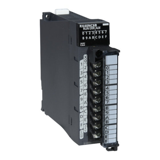
PART NAMES This chapter describes the part names of the I/O module with diagnostic functions. (11) (11) (10) Name Description RUN LED Displays the operating status. On: Operating Off: When 5V power supply was disconnected or a watchdog timer error occurred ERR LED This part is combined with an I/O status indicator LED to display the error occurrence status at each I/O terminal. - Page 127 *1 For details, refer to the following. Page 200 List of Error Codes *2 The LED and terminal block are added to the module with production information (first four digits) of "0202" or later. *3 For details, refer to the following. Page 155 Safety module operation 5 PART NAMES...
-
Page 128: Chapter 6 Specifications
SPECIFICATIONS This chapter describes the performance specifications and function list of the I/O module with diagnostic functions in SIL2 mode. Performance Specifications This section describes the performance specifications of the I/O module with diagnostic functions in SIL2 mode. Input module with diagnostic functions Item Specifications Number of input points... - Page 129 ■Circuit configuration TB16 Internal circuit CON1 CON2 TB17 Constant- voltage circuit TB18 ■Terminal layout Viewed from the front of the module 24VDC CON1 CON2 The names X00 to X0F, T0, and T1 are signal names. The numbers 1 to 18 indicate terminal numbers in the 18-point terminal block. CON1 and CON2 indicate terminal numbers of the terminal block for test pulse output.
- Page 130 Output module with diagnostic functions Item Specifications Number of output points Rated load voltage 24VDC (Allowable voltage range: 20.4 to 28.8VDC) Maximum load current 0.5A/point, 5A/common Maximum inrush current Current is to be limited by the overload protection function. Leakage current at OFF 0.3mA or lower Maximum voltage drop at ON 1.0VDC (TYP.) 0.5A...
- Page 131 ■Circuit configuration Internal circuit TB16 TB17 Constant-voltage circuit TB18 ■Terminal layout Viewed from the front of the module The names Y00 to Y0F are single names. The numbers 1 to 18 indicate terminal numbers. ■Safety output response time for SIL2 mode The safety output response time for SIL2 mode refers to the time taken until the safety data is output to an output device after it is transferred from the head module.
-
Page 132: Function List
Function List The following table lists the functions of the I/O module with diagnostic functions in SIL2 mode. Item Description Reference Safety input function Input double wiring function Turns input wiring into double wiring. Page 160 Input double wiring function Input response time setting Reduces nose in input signals. -
Page 133: Chapter 7 Procedures Before Operation
PROCEDURES BEFORE OPERATION This chapter describes procedures before operation for using the I/O module with diagnostic functions in SIL2 mode. Installation procedure Installing the battery Install the battery on the SIL2 Process CPU in both systems. ( MELSEC iQ-R CPU Module User's Manual (Startup)) Installing an extended SRAM cassette and SD memory card As necessary, install an extended SRAM cassette and SD memory card on the SIL2 Process CPU in both systems. - Page 134 Setting parameters on the remote head module side Set the system parameters, CPU parameters, and module parameters of each module. • System parameter and CPU parameter setting (Page 150 Creating a new project (remote head module side), Page 150 Setting parameters on the remote head module side) •...
- Page 135 Initializing the SIL2 Process CPU Use the engineering tool to initialize the SIL2 Process CPU. ( MELSEC iQ-R CPU Module User's Manual (Startup)) Initialize one SIL2 Process CPU and then connect the other SIL2 Process CPU to the personal computer. Then, initialize the SIL2 Process CPU in the same way.
- Page 136 Checking LEDs on the SIL2 Process CPU side Check that the LED status of each module is as follows. The CARD READY LED turns on or off depending on whether the SD memory card is installed. • Control system • Standby system *1 For the redundant master station system, the MST LED of the standby system master/local module flashes.
- Page 137 Operation check procedure Checking Check the status of each module used in the system and program behaviors. • Check each module to see whether an error occurred. • Check that the LED status of each module is as follows. • Control system •...
- Page 138 Program execution Power off the SIL2 Process CPU and remote head module in both systems. Then, set the RUN/STOP/RESET switch for the SIL2 Process CPU and remote head module in both systems to RUN, and turn the power of both systems on. Check that the SIL2 Process CPU PROGRAM RUN LED for the control system turns on.
-
Page 139: Chapter 8 System Configuration
SYSTEM CONFIGURATION This chapter describes the system configurations for using the I/O module with diagnostic functions in SIL2 mode. For application in SIL2 mode, a redundant system must be configured based on a redundant master station or redundant line. In such a case, mount the I/O module with diagnostic functions to a remote head module. - Page 140 • List of components Name Description System A system Composed of the following modules: • RnPSFCPU • R6PSFM • R6RFM • RJ71GF11-T2 ■Precautions • Each module has restrictions on use in a system on the system configuration diagram. For details, refer to the User's Manual (Application) for each module.
-
Page 141: Redundant Line
Redundant Line The following diagram shows the system configuration with a redundant line. • System configuration diagram 8 SYSTEM CONFIGURATION 8.2 Redundant Line... - Page 142 • List of components Name Description System A system Composed of the following modules: • RnPSFCPU • R6PSFM • R6RFM • RJ71GF11-T2 ■Precautions • Each module has restrictions on use in a system on the system configuration diagram. For details, refer to the User's Manual (Application) for each module.
-
Page 143: Firmware Version For Sil2 Mode
Firmware Version for SIL2 Mode For application in SIL2 mode, use the I/O module with diagnostic functions with the following condition. • Use a module whose firmware version is 02 or later. For details on how to check the firmware version, refer to MELSEC iQ-R Module Configuration Manual. 8 SYSTEM CONFIGURATION 8.3 Firmware Version for SIL2 Mode... -
Page 144: Chapter 9 Installation And Wiring
(Q6TE-18SN), 0.3 to 1.5 (22 to 16 AWG) cables can be used. To use cables bigger than the above, manage by using FA goods manufactured by Mitsubishi Electric Engineering Co., Ltd. (such as FA- TB161AC+ FA-CBL20D). - Page 145 Wiring the terminal block for test pulse output ■Tightening torque Tighten terminal block mounting screws within the following torque range. If screws are tightened excessively, the module's case may be damaged. Screw location Tightening torque range Terminal block mounting screw (M2.5 screw) 0.2 to 0.3Nm ■Cable to be used The following table shows the cable to be connected to the terminal block for test pulse output.
- Page 146 ■Mounting a cable Insert a cable with a bar solderless terminal into the insertion slot and push the cable in. After pushing the cable in, pull it lightly to check that it is clamped securely in place. ■Removing a cable Using a flathead screwdriver, push in the open/close button for the cable to be removed.
-
Page 147: Wiring Examples
Wiring Examples This section shows examples of wiring of parts such as an emergency stop switch and start/stop/reset switch. Double wiring (using test pulse outputs) With two input modules with diagnostic functions, an emergency stop switch is wired as follows: RX40NC6B(Main) RX40NC6B(Sub) DC24V... - Page 148 Safety (door) switch wiring With two input modules with diagnostic functions, a safety (door) switch is wired as follows: RX40NC6B(Main) RX40NC6B(Sub) Open DC24V DC24V Open 24VDC (1) This is a door switch with two normally closed contacts based on direct opening action. Connect this door switch between X00 to X0F (input) terminals and T0 (test pulse output) terminals.
- Page 149 Light curtain and laser scanner wiring With two input modules with diagnostic functions, a light curtain and laser scanner are wired as follows: Optical transmitter 24VDC Synchronization - Synchronization + RX40NC6B(Main) RX40NC6B(Sub) Optical receiver Synchronization + Synchronization - 24VDC Control output 1 Control output 2 DC24V DC24V...
- Page 150 Electromagnetic contactor wiring With an input module with diagnostic functions and output module with diagnostic functions, electromagnetic contactors are wired as follows: RX40NC6B(Main) RX40NC6B(Sub) RY40PT5B(Main) (1)(2) Electromagnetic contactor (1)(2) Electromagnetic contactor 24VDC 24VDC 24VDC (1) Connect contactor safety separation contacts (for turning off sub-normally-closed-contacts when main contacts are welded) between X00 to X0F (input) terminals and T0 and T1 (test output) terminals.
-
Page 151: Chapter 10 Functions
FUNCTIONS This chapter describes the details of the functions that can be used in the I/O module with diagnostic functions in SIL2 mode and their setting procedures. For details on safety I/O signals, I/O signals, and buffer memory areas, refer to the following. Page 202 Safety I/O Signals Page 205 I/O Signals Page 209 Buffer Memory... -
Page 152: Sil2 Mode
10.1 SIL2 Mode This section describes the settings necessary for operating the I/O module with diagnostic functions in SIL2 mode. Page 137 SYSTEM CONFIGURATIONWith the system shown in Page 137 SYSTEM CONFIGURATION configured, the following settings must be configured for each module and system. Creating a new project (remote head module side) Create a new project with the remote head module, and add necessary modules. - Page 153 Creating a new project (SIL2 Process CPU side) Create a new project with the SIL2 Process CPU, and add necessary modules. Create a project with the SIL2 Process CPU. [Project] [New] Add the user "Administrators" to the project and save the project. Initialize the SIL2 Process CPU (built-in memory and user information) in both systems.
- Page 154 Parameter setting on the SIL2 Process CPU side With the created project, set the parameters. Set "CPU Parameter" according to the system configuration. For details on the items and setting method, refer to MELSEC iQ-R CPU Module User's Manual (Application). Set "Required Settings"...
- Page 155 Safety communication setting Set safety communications using the project on the remote head module side. For details on safety communications, refer to the MELSEC iQ-R CC-Link IE Field Network User's Manual (Application). Open a project on the SIL2 Process CPU side. Set "To Use or Not to Use the Safety Communication Setting"...
- Page 156 Select the check box for the safety communication setting target module, and click the [Add] button. In the "Safety Communication Setting" window, set safety communications for the added module. Item Description Sending Interval Monitoring Time [ms] Refer to the following manual and set a value appropriate to your system. ...
- Page 157 Safety module operation With "Safety Module Operation" in the engineering tool, enable the RX40NC6B (Main) or the RY40PT5B (Main) so that it can be used in SIL2 mode. When performing the safety module operation, observe the following. • Ensure that the engineering tool is directly connected to the SIL2 Process CPU in the control system (specify "No Specification"...
- Page 158 Select the check box for the RX40NC6B (Main) or the RY40PT5B (Main) to be enabled, and click the [S MODE LED Start Flashing] button. Check that the S MODE LED for the I/O modules with diagnostic functions (Main and Sub) to be enabled is flashing (0.4s cycle).
- Page 159 Click the [Enable] button. In this case, the current enabled/disabled status of the safety module is displayed for "Module Status". Module Status Description The information is not acquired. Valid (Reset Wait) The safety module has just been enabled. In this state, the I/O module with diagnostic functions needs to be reset, and the module status will be enabled after the reset.
- Page 160 ■Disabling the safety module Modules enabled by "Safety Module Operation" need to be disabled when using them in normal mode. To disable the modules, follow the procedure below. In the "Safety Module Operation" window, select the check box for the RX40NC6B (Main) or the RY40PT5B (Main) to be disabled, and click the [Disable] button.
- Page 161 • Remote head module side *1 Because the remote head module is not in a redundancy configuration for the redundant master station system, the following LEDs are always turned off. CTRL LED SBY LED Check that no error occurred in CC-Link IE Field Network diagnostics. (...
-
Page 162: Safety Input Function
10.2 Safety Input Function Input double wiring function This function turns input wiring into double wiring. With double wiring, input signals on each side are verified so that when one side fails, safety inputs can be turned off. RX40NC6B(Main) RX40NC6B(Sub) Double wiring combination For double wiring, perform wiring on a terminal with the same terminal number in both the RX40NC6B (Main) and the RX40NC6B (Sub). - Page 163 Double input combination The input module with diagnostic functions evaluates an input signal's logic and reflects the result in the relevant safety input (SA\X). When double inputs are made with different signals, a double input discrepancy detection state arises. The following table shows the correspondences between double input signal statuses and safety inputs (SA\X).
-
Page 164: Input Response Time Setting Function
Input response time setting function This function helps change the input response time of the input module with diagnostic functions on a per-point basis. The input module with diagnostic functions takes in external inputs with the set input response times. External input Input signal in the module t: Input response time... -
Page 165: Input Hold Function
Input HOLD function This function holds input values when safety refresh data reception is interrupted. Input HOLD occurrence When detecting an interruption of safety refresh data reception, the input module with diagnostic functions holds the inputs immediately before that interruption. Input HOLD release After an input HOLD occurs (safety refresh data reception is interrupted), when safety refresh data is received normally within the time set with "Safety I/O Hold Time"... -
Page 166: External Input Monitor Function
External input monitor function With External input monitor signal (Un\G1024, Un\G1028), the ON/OFF state of an external input terminal can be checked on a per-point basis. Because external input signals can be monitored regardless of the double input combinations for the input double wiring function, the cause can be investigated easily when a double input discrepancy occurs. -
Page 167: Safety Output Function
10.3 Safety Output Function Output double wiring function This function turns output wiring into double wiring. With double wiring, output signals on each side are verified so that when one side fails, safety outputs can be turned off. Electromagnetic contactor RY40PT5B(Main) Electromagnetic contactor... - Page 168 Setting procedure With "Wiring output selection", set the terminal to perform double wiring on. [Navigation window] [Parameter] [Module Information] Model [Module Parameter] [Basic setting] "Wiring output selection" • When "Not used" is selected for "Wiring output selection", the applicable output terminals are always OFF. •...
-
Page 169: Output Hold Function
Output HOLD function This function holds output values when safety refresh data reception is interrupted. Output HOLD occurrence When detecting an interruption of safety refresh data reception, the output module with diagnostic functions holds the outputs immediately before that interruption. Output HOLD release After an output HOLD occurs (safety refresh data reception is interrupted), when safety refresh data is received normally within the time set with "Safety I/O Hold Time"... -
Page 170: Input Diagnostic Function
10.4 Input Diagnostic Function Double input discrepancy detection function This function identifies failures by monitoring the discrepancy state of double safety inputs (SA\X). Double input discrepancy detection ■Double input discrepancy detection (input discrepancy detection time specified) In the "Application setting" window, when "Redundant input discrepancy detection settings" is set to "Enabled" and "Redundant input discrepancy detection type"... - Page 171 ■Double input discrepancy detection (input discrepancy detection time not specified) In the "Application setting" window, when "Redundant input discrepancy detection settings" is set to "Enabled" and "Redundant input discrepancy detection type" is set to "Discrepancy detection time not specified", even if the double input discrepancy state continues, a double input discrepancy detection error will not occur.
- Page 172 • When a double input discrepancy detection error occurs After the input terminals turn into the state of ON/ON, when the discrepancy state (ON/OFF or OFF/ON) continues for longer than 500ms, a double input discrepancy will be detected and a double input discrepancy detection state will arise. A double input discrepancy detection error (error code: 1400H) will not occur.
- Page 173 ■Application example of the double input discrepancy detection (input discrepancy detection time not specified) Use this function when the double input discrepancy detection time cannot be uniformly determined. With this function, a double input discrepancy detection error occurs not immediately after the discrepancy is detected, but only when a certain condition is satisfied.
- Page 174 ■Setting procedure Perform this setting with "Redundant input discrepancy detection settings" and "Redundant input discrepancy detection type". [Navigation window] [Parameter] [Module Information] Model [Module Parameter] "Application setting" "Redundant input discrepancy detection settings" and "Redundant input discrepancy detection type" •...
- Page 175 ■Guidelines on double input discrepancy detection time Condition Guidelines on double input discrepancy detection time For a mechanical switch Set the time around 100ms. For a sensor input Set the time around 20ms. When double input synchronization time can be defined For input equipment with specifications for synchronization time open to the public, set a value determined by considering the safety factor for misdetections.
- Page 176 ■Double input discrepancy auto recovery enabled signal When "Auto recovery settings after discrepancy error" is set to "Enable", 1 is stored in Double input discrepancy auto recovery enabled signal (Un\G1032). For details on Double input discrepancy auto recovery enabled signal (Un\G1032), refer to the following.
-
Page 177: Input Dark Test Function
Input dark test function This function outputs test pulses to turn off external input signal (X00 to X0F) that are ON and diagnoses contacts including external devices for failure. Such a fault as adhesion, short-circuit, and failure in a circuit can be detected. Also, the test pulse OFF time or the number of pulses to be output that are used for one diagnosis process can be set according to the usage environment. - Page 178 Setting procedure Set the parameters for the input dark test function with "Application setting". There is a correlation between an input response time and input dark test parameter values. To set parameters, set values that satisfy their correlation. For details, refer to the following. Page 162 Correlation between an input response time and input dark test parameters With "Input dark test execution setting", set whether to conduct an input dark test on a per-point basis.
-
Page 179: Output Diagnostic Function
10.5 Output Diagnostic Function Output dark test function This function outputs test pulses to turn off external output signal (Y00 to Y0F) that are ON and diagnoses internal circuits for failure. Such a fault as adhesion, wire breaks, and failure in a circuit can be detected. Also, the test pulse OFF time or the number of pulses to be output that are used for one diagnosis process can be set according to the usage environment. - Page 180 Setting procedure Set the parameters for the output dark test function with "Application setting". With "Output dark test execution setting", set whether to conduct an output dark test on a per-point basis. [Navigation window] [Parameter] [Module Information] Model [Module Parameter] [Application setting] "Output dark test function"...
-
Page 181: Output Read-Back Function
Output read-back function This function reads back the output results for diagnosis to see if the external output signals (Y00 to Y0F) are turned ON or OFF correctly. By performing diagnostics to see if the output terminal state and the safety device output data match, the function detects an error in the module's output operation. -
Page 182: Protection Function
10.6 Protection Function The following table lists protection functions. Function name Purpose Description Module power supply overvoltage protection Protects against ignition and burnout originated from Activated when an overvoltage occurs in the module the I/O module with diagnostic functions due to an power supply. -
Page 183: Common Functions Of The I/O Module With Diagnostic Functions
10.7 Common Functions of the I/O Module with Diagnostic Functions LED indication setting on error condition This function helps set the indication of the I/O status indicator LED when a minor error occurs. The following figure shows the LED status in normal and abnormal conditions. Normal condition Error condition I/O status... -
Page 184: Error History Function
10.8 Error History Function For the errors that occurred in the I/O module with diagnostic functions, a maximum of 16 error histories can be checked using the engineering tool. [Diagnostics] [System Monitor] Right-click the target module. [Module Diagnostics] When the number of error histories exceeds 16, the histories are overwritten sequentially from the first one, and error histories are continued to be recorded. -
Page 185: Event History Function
10.9 Event History Function This function collects errors that occurred in the I/O module with diagnostic functions and executed operations as event information in the remote head module. Information of an event that occurred in the I/O module with diagnostic functions is collected by the remote head module and held inside the data memory in the remote head module. - Page 186 Event history list The following table shows an event that occurs in the I/O module with diagnostic functions. Event Event Event name Description Additional code classification information 00150 Information Safety communication start Safety communications were started. 00151 Information Safety communication stop Safety communications were stopped.
-
Page 187: Chapter 11 Parameter Settings
PARAMETER SETTINGS This chapter describes how to set the parameters of the I/O module with diagnostic functions. 11.1 Basic Settings Setting procedure Open "Basic setting" of the engineering tool. Start Module Parameter. [Navigation window] [Parameter] [Module Information] Target module [Module Parameter] [Basic setting] Double-click on the item to be changed and enter a setting value. -
Page 188: Application Settings
11.2 Application Settings Setting procedure Open "Application setting" of the engineering tool. Start Module Parameter. [Navigation window] [Parameter] [Module Information] Target module [Module Parameter] [Application setting] Double-click on the item to be changed and enter a setting value. •... -
Page 189: Refresh Settings
11.3 Refresh Settings Module parameter refresh settings are not available for the I/O module with diagnostic functions that is set to SIL2 mode. 11 PARAMETER SETTINGS 11.3 Refresh Settings... -
Page 190: Chapter 12 Maintenance And Inspection
MAINTENANCE AND INSPECTION This chapter describes inspection to be performed for using the I/O module with diagnostic functions in SIL2 mode. Periodic inspection Perform the following inspection one or two times in 6 months to a year. Perform it as well after equipment is transferred or modified, or wiring is changed. - Page 191 MEMO 12 MAINTENANCE AND INSPECTION...
-
Page 192: Chapter 13 Troubleshooting
TROUBLESHOOTING This chapter describes the details of errors that may occur when using the I/O module with diagnostic functions and troubleshooting. 13.1 Troubleshooting with the LEDs By checking the LED indicator status, primary diagnostics without the engineering tool can be performed to narrow down the range of causes of error occurrences. -
Page 193: Checking The Module Status
13.2 Checking the Module Status The following functions are available in the "Module Diagnostics" window for the I/O module with diagnostic functions. Function Application Error Information Displays the details of the currently occurring error. Click the [Event History] button to check the histories of errors that occurred on the network as well as histories of errors detected in modules and executed operations. - Page 194 Module Information List Status information of the I/O module with diagnostic functions can be checked by selecting the "Module Information List" tab. Item Description LED information Displays the status of each LED of the I/O module with diagnostic functions. External input monitor signal X00 to X0F (SIL2 mode MAIN) Displays the status of external input for each input.
-
Page 195: Troubleshooting By Symptom
13.3 Troubleshooting by Symptom When the I/O module with diagnostic functions does not start up Check item Action Check whether five seconds have elapsed after power-off of the power supply When applying the input power source to the power supply module again, do module. -
Page 196: When The S Mode Led Is Flashing Or Off
When the S MODE LED is flashing or off When the S MODE LED is flashing (1s cycle) Check item Action Check whether the status is "Safety station interlock status". Monitor the 'safety station interlock status on a per-safety connection basis (1st module)' (SA\SD1232 to SA\SD1239) , and check the interlock status of the I/O module with diagnostic functions. -
Page 197: When The Alm Led Is Flashing
When the ALM LED is flashing Check item Action Check whether the system was restarted after the activation of the safety When the safety module is enabled, restart the system. module. When an I/O LED does not change Check item Action Check whether "Display I/O status and error switching (1 second interval)"... -
Page 198: When The On/Off State Of An External Output Cannot Be Changed
When the ON/OFF state of an external output cannot be changed Check the following items in order of No. Check item Action Check whether the S MODE LED is on. If the S MODE LED is not on, take action by referring to the following. Page 194 When the S MODE LED is flashing or off When the safety output is turned on, check whether the If the LED is on, there is a problem in the wiring between the external output... -
Page 199: When A Load Momentarily Turns On Before Establishment Of The Safety Connection
When a load momentarily turns on before establishment of the safety connection Check item Action Check whether a load momentarily turns on in the following condition: Use a load or device with the response speed of 1ms or longer. Depending on the capacity (C) between the drain and source of a MOSFET, the load current may flow as shown in the figure below, and thus the load may momentarily turn on before establishment of the safety connection of the output module with diagnostic functions (before the S MODE LED of the... -
Page 200: Troubleshooting While Proceeding Procedures Before Operation
13.4 Troubleshooting While Proceeding Procedures Before Operation When the module parameter write to the remote head module fails Refer to the following. MELSEC iQ-R CC-Link IE Field Network Remote Head Module User's Manual (Application) Troubleshooting on the "Safety Communication Setting" window When [Import Setting] cannot be performed to the project of the remote head module Check item Action... - Page 201 When "Timeout" is displayed for "Module Status" Check the following items in order of No. Check item Action Check whether LEDs of the I/O module with diagnostic functions are A moderate error occurred in the I/O module with diagnostic functions. The in the following states.
-
Page 202: List Of Error Codes
13.5 List of Error Codes When an error occurs while the I/O module with diagnostic functions is running, its error code can be checked in the module diagnostics window of GX Works3. Additionally, Error flag (X10) turns on when an error occurs. Error codes of the I/O module with diagnostic functions are classified into minor errors and moderate errors. - Page 203 Error code Error name Error description and cause Action 1500H Safety I/O HOLD time exceeded Duration of I/O HOLD state exceeded the set • Check that no error occurred on the switching of error time. systems incorporating SIL2 Process CPUs. •...
-
Page 204: Appendices (Sil2 Mode)
APPENDICES (SIL2 MODE) Appendix 8 Safety I/O Signals List of safety I/O signals This section shows a list of safety I/O signals for the I/O module with diagnostic functions in SIL2 mode. For details on the safety I/O signals, refer to the following. Page 204 Safety input signal details Page 204 Safety output signal details •... - Page 205 Output module with diagnostic functions ■Safety input signal Device number Signal name SA\X0 to SA\XF Use prohibited ■Safety output signal Device number Signal name SA\Y0 Safety output signal Y0 SA\Y1 Safety output signal Y1 SA\Y2 Safety output signal Y2 SA\Y3 Safety output signal Y3 SA\Y4 Safety output signal Y4...
-
Page 206: Safety Input Signal Details
Safety input signal details This section describes the details on the safety input signals for the I/O module with diagnostic functions in SIL2 mode that are assigned to the CPU module. The safety I/O numbers (SA\X/SA\Y) described in this section are the safety I/O numbers when 0 is set as the start number with the safety data transfer device setting in the safety communication setting window. -
Page 207: Appendix 9 I/O Signals
Appendix 9 I/O Signals List of I/O signals This section describes a list of I/O signals for the I/O module with diagnostic functions in SIL2 mode. For details on the I/O signals, refer to the following. Page 206 Details on input signals Page 208 Details on output signals •... -
Page 208: Details On Input Signals
Details on input signals This section describes the details on the input signals for the I/O module with diagnostic functions that are assigned to the CPU module. This section describes the I/O numbers (X/Y) when 0 is set as the start I/O number of the I/O module with diagnostic functions. - Page 209 Module READY This signal is used as an interlock condition to read/write data from/to the CPU module. When the initial processing of the I/O module with diagnostic functions is completed after the CPU module is powered on or is reset, Module READY (X1F) turns off. When a watchdog timer error occurs, Module READY (X1F) turns on.
-
Page 210: Details On Output Signals
Details on output signals This section describes the details on the output signals for the I/O module with diagnostic functions that are assigned to the CPU module. This section describes the I/O numbers (X/Y) when 0 is set as the start I/O number of the I/O module with diagnostic functions. -
Page 211: Appendix 10Buffer Memory
Appendix 10 Buffer Memory List of buffer memory areas The following tables list the buffer memory areas of the I/O module with diagnostic functions. For details on the buffer memory areas, refer to the following. Page 212 Details of buffer memory areas The buffer memory areas of the I/O module with diagnostic functions are intended only for monitor data (data used for referring to the status of the I/O module with diagnostic functions). - Page 212 Error history areas (Un\G0 to Un\G255) Address Address Name Default value (decimal) (hexadecimal) Latest address of error history 1 to 15 1H to FH System area Error history No.1 Error code Error time First two digits of Last two digits of the year the year Month...
- Page 213 System areas (Un\G256 to Un\G511) Address Address Name Default value (decimal) (hexadecimal) 256 to 511 100H to 1FFH System area Monitor areas (Un\G512 to Un\G2047) ■Input module with diagnostic functions Address Address Name Default value (decimal) (hexadecimal) 200H Latest error code 513 to 523 201H to 20BH System area...
-
Page 214: Details Of Buffer Memory Areas
Details of buffer memory areas This section describes the details of buffer memory areas of the I/O module with diagnostic functions. Latest address of error history This area shows the buffer memory address where the latest error history is stored. ■Buffer memory address The following table shows the buffer memory address of this area. - Page 215 Latest error code The latest error code detected in the I/O module with diagnostic functions is stored. For details, refer to the following. Page 200 List of Error Codes ■Buffer memory address The following table shows the buffer memory address of this area. Buffer memory name X/Y00 to X/Y0F Latest error code...
- Page 216 ■Buffer memory address The following table shows the buffer memory addresses of these areas. Buffer memory name X00 to X0F External input monitor signal X00 to X0F (SIL2 mode Main) 1024 External input monitor signal X00 to X0F (SIL2 mode Sub) 1028 Double input discrepancy auto recovery enabled signal The setting status of "Auto recovery settings after discrepancy error"...
- Page 217 Input dark test error detection state An input dark test error detection state is stored in this area when "Input dark test execution setting" is set to "Perform". This area turns on when an input dark test error occurs. (1) 0: Normal, 1: Error ■Buffer memory address The following table shows the buffer memory address of this area.
-
Page 218: Appendix 11 Calculation Method Of Safety Response Time (Maximum Value)
Appendix 11 Calculation Method of Safety Response Time (Maximum Value) The safety response time is the maximum time taken from when the safety input of the RX40NC6B (intelligent device station (safety station)) turns off until the safety output of the RY40PT5B (intelligent device station (safety station)) turns off (the time including an error detection). -
Page 219: Appendix 12External Dimensions
Appendix 12 External Dimensions The following figures show the external dimensions of the I/O module with diagnostic functions. Input module with diagnostic functions 27.8 (Unit: mm) *1 The terminal block for test pulse output is added to the module with production information (first four digits) of "0202" or later. Output module with diagnostic functions 27.8 (Unit: mm) -
Page 220: Index
INDEX ..... . 77 ....91 Alarm clear request Latest address of alarm history . - Page 221 ..102 Output delay function enable/disable ....103 Output delay time setting ....102 Output delay type setting Output disconnection detection automatic clear .
-
Page 222: Revisions
Japanese manual number: SH-081620-D This manual confers no industrial property rights or any rights of any other kind, nor does it confer any patent licenses. Mitsubishi Electric Corporation cannot be held responsible for any problems involving industrial property rights which may occur as a result of using the contents noted in this manual. -
Page 223: Warranty
WARRANTY Please confirm the following product warranty details before using this product. 1. Gratis Warranty Term and Gratis Warranty Range If any faults or defects (hereinafter "Failure") found to be the responsibility of Mitsubishi occurs during use of the product within the gratis warranty term, the product shall be repaired at no cost via the sales representative or Mitsubishi Service Company. - Page 224 1. Limited Warranty and Product Support. a. Mitsubishi Electric Company ("MELCO") warrants that for a period of eighteen (18) months after date of delivery from the point of manufacture or one year from date of Customer's purchase, whichever is less, Mitsubishi programmable logic controllers (the "Products") will be free from defects in material and workmanship.
- Page 225 g. The Product information and statements contained on MELCO's website and in catalogs, manuals, technical bulletins or other materials provided by MELCO are provided as a guide for Customer's use. They do not constitute warranties and are not incorporated in the contract of sale for the Products. h.
-
Page 226: Trademarks
TRADEMARKS The company names, system names and product names mentioned in this manual are either registered trademarks or trademarks of their respective companies. In some cases, trademark symbols such as ' ' or ' ' are not specified in this manual. SH(NA)-081621ENG-D... - Page 228 SH(NA)-081621ENG-D(2211)MEE MODEL: R-DFIO-U-OU-E MODEL CODE: 13JX51 HEAD OFFICE : TOKYO BUILDING, 2-7-3 MARUNOUCHI, CHIYODA-KU, TOKYO 100-8310, JAPAN NAGOYA WORKS : 1-14 , YADA-MINAMI 5-CHOME , HIGASHI-KU, NAGOYA , JAPAN When exported from Japan, this manual does not require application to the Ministry of Economy, Trade and Industry for service transaction permission.
Need help?
Do you have a question about the MELSEC iQ-RX40NC6B and is the answer not in the manual?
Questions and answers