Sign In
Upload
Manuals
Brands
Mitsubishi Electric Manuals
Control Unit
MELSEC iQ-RX40NC6B
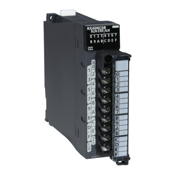
Mitsubishi Electric MELSEC iQ-RX40NC6B Manuals
Manuals and User Guides for Mitsubishi Electric MELSEC iQ-RX40NC6B. We have
2
Mitsubishi Electric MELSEC iQ-RX40NC6B manuals available for free PDF download: Application User's Manual, User Manual
Mitsubishi Electric MELSEC iQ-RX40NC6B Application User's Manual (228 pages)
I/O Module (With Diagnostic Functions)
Brand:
Mitsubishi Electric
| Category:
Control Unit
| Size: 4.86 MB
Table of Contents
Safety Precautions
3
Conditions of Use for the Product
13
Compliance with Emc and Low Voltage Directives
14
Introduction
14
Table of Contents
15
Relevant Manuals
19
Generic Terms and Abbreviations
20
Terms
20
Part 1 Normal Mode
21
Chapter 1 Functions
22
Input Function
22
Input Response Time Setting Function
23
Input HOLD/CLEAR Function
24
Input Delay Function
26
Number of Input on Times Integration Function
29
Event Time Stamp Function
32
Output Function
35
Setting of Output Mode at Error
35
Output Delay Function
36
Number of Output on Times Integration Function
38
Common Functions of the I/O Module with Diagnostic Functions
41
Interrupt Function
41
LED Indication Setting on Error Condition
44
Diagnostic Function
45
Input Disconnection Detection Function
45
Output Disconnection Detection Function
48
Short-Circuit Detection Function
51
Error History Function
53
Event History Function
56
Chapter 2 Parameter Settings
57
Basic Settings
57
Application Settings
58
Interrupt Settings
59
Refresh Settings
60
Refresh Processing Time
61
Chapter 3 Troubleshooting
62
Troubleshooting with the Leds
62
When the RUN LED Turns off
62
When the ERR LED Turns on
62
When the ALM LED Turns on
62
When an I/O LED Does Not Change
62
Checking the Module Status
63
Troubleshooting by Symptom
66
When the I/O Module with Diagnostic Functions Does Not Start up
66
When the ON/OFF State of an External Input Cannot be Read
66
When a Disconnection in the Input Wiring Cannot be Detected
67
When a Disconnection in the Input Wiring Cannot be Detected Correctly
67
When a Disconnection was Detected in the Input Wiring
67
When the ON/OFF State of an External Output Cannot be Changed
68
When a Disconnection or Short-Circuit in the Output Wiring Cannot be Detected
68
When a Disconnection or Short-Circuit in the Output Wiring Cannot be Detected Correctly
68
When a Disconnection or Short-Circuit was Detected in the Output Wiring
68
When a Load Momentarily Turns on before the Completion of the Initial Processing
69
List of Error Codes
70
List of Alarm Codes
72
Appendices (Normal Mode)
73
Appendix 1 Module Label
73
Appendix 2 I/O Signals
75
List of I/O Signals
75
Details on Input Signals
77
Details on Output Signals
79
Appendix 3 Buffer Memory
81
List of Buffer Memory Addresses
81
Details of Buffer Memory Addresses
92
Appendix 4 Optional Item
119
Spring Clamp Terminal Block
119
Appendix 5 Disabling the Safety Module
120
Appendix 6 Using the Module in the Redundant System with Redundant Extension Base Unit
121
Restrictions on Functions and Specifications
121
Precautions
121
Appendix 7 Added or Modified Function
122
Part 2 Sil2 Mode
123
Chapter 4 Overview
124
Chapter 5 Part Names
126
Chapter 6 Specifications
128
Performance Specifications
128
Function List
132
Chapter 7 Procedures before Operation
133
Chapter 8 System Configuration
139
Redundant Master Station
139
Redundant Line
141
Firmware Version for SIL2 Mode
143
Chapter 9 Installation and Wiring
144
Before Using the I/O Module with Diagnostic Functions
144
Wiring
144
Wiring Examples
147
Chapter 10 Functions
151
SIL2 Mode
152
Safety Input Function
162
Input Double Wiring Function
162
Input Response Time Setting Function
164
Input HOLD Function
165
External Input Monitor Function
166
Safety Output Function
167
Output Double Wiring Function
167
Output HOLD Function
169
Input Diagnostic Function
170
Double Input Discrepancy Detection Function
170
Input Dark Test Function
177
Output Diagnostic Function
179
Output Dark Test Function
179
Output Read-Back Function
181
Protection Function
182
Common Functions of the I/O Module with Diagnostic Functions
183
LED Indication Setting on Error Condition
183
Error History Function
184
Event History Function
185
Chapter 11 Parameter Settings
187
Basic Settings
187
Application Settings
188
Refresh Settings
189
Chapter 12 Maintenance and Inspection
190
Chapter 13 Troubleshooting
192
Troubleshooting with the Leds
192
Checking the Module Status
193
Troubleshooting by Symptom
195
When the I/O Module with Diagnostic Functions Does Not Start up
195
When the RUN LED Is off
195
When the ERR LED Is Flashing or Turns on
195
When the S MODE LED Is Flashing or off
196
When the ALM LED Is Flashing
197
When an I/O LED Does Not Change
197
When a Module Parameter Error Is Displayed in the "Module Diagnostics" Window
197
When the ON/OFF State of an External Input Cannot be Read
197
When the ON/OFF State of an External Output Cannot be Changed
198
When an External Output on Signal Intermittently Turns off
198
When a Load Momentarily Turns on before Establishment of the Safety Connection
199
Troubleshooting While Proceeding Procedures before Operation
200
When the Module Parameter Write to the Remote Head Module Fails
200
Troubleshooting on the "Safety Communication Setting" Window
200
Troubleshooting on the "Safety Module Operation" Window
200
List of Error Codes
202
Appendices (Sil2 Mode)
204
Appendix 8 Safety I/O Signals
204
List of Safety I/O Signals
204
Safety Input Signal Details
206
Safety Output Signal Details
206
Appendix 9 I/O Signals
207
List of I/O Signals
207
Details on Input Signals
208
Details on Output Signals
210
Appendix 10Buffer Memory
211
List of Buffer Memory Areas
211
Details of Buffer Memory Areas
214
Appendix 11 Calculation Method of Safety Response Time (Maximum Value)
218
Appendix 12External Dimensions
219
Index
220
Revisions
222
Warranty
223
Trademarks
226
Advertisement
Mitsubishi Electric MELSEC iQ-RX40NC6B User Manual (44 pages)
I/O Module (With Diagnostic Functions)
Brand:
Mitsubishi Electric
| Category:
Control Unit
| Size: 1.18 MB
Table of Contents
Safety Precautions
3
Conditions of Use for the Product
12
Compliance with Emc and Low Voltage Directives
13
Introduction
13
Table of Contents
15
Relevant Manuals
16
Terms
16
Chapter 1 Part Names
17
Chapter 2 Specifications
19
Performance Specifications
19
Input Module with Diagnostic Functions
19
Output Module with Diagnostic Functions
21
Chapter 3 Function List
23
Chapter 4 Procedures before Operation
25
Chapter 5 Installation and Wiring
27
Before Using the I/O Modules with Diagnostic Functions
27
Input Module with Diagnostic Functions
27
Output Module with Diagnostic Functions
28
Wiring
30
Input Wiring Examples
31
Appendices
32
Appendix 1 External Dimensions
32
Index
36
Revisions
38
Warranty
39
Trademarks
42
Advertisement
Related Products
Mitsubishi Electric MELSEC iQ-R-RD75P4
Mitsubishi Electric MELSEC iQ-R-RD75P2
Mitsubishi Electric MELSEC iQ-R-RD75D2
Mitsubishi Electric MELSEC iQ-R-RD75D4
Mitsubishi Electric MELSEC iQ-R60DA4
Mitsubishi Electric MELSEC iQ-R60DAV8
Mitsubishi Electric MELSEC iQ-R60DAI8
Mitsubishi Electric MELSEC iQ-RY40PT5B
Mitsubishi Electric MELSEC iQ-RJ71DN91
Mitsubishi Electric MELSEC iQ-F-FX5-40SSC-S
Mitsubishi Electric Categories
Air Conditioner
Controller
Projector
Inverter
Heat Pump
More Mitsubishi Electric Manuals
Login
Sign In
OR
Sign in with Facebook
Sign in with Google
Upload manual
Upload from disk
Upload from URL