Table of Contents
Advertisement
Quick Links
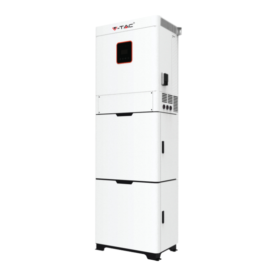
HYBRID SOLAR INVERTER SINGLE PHASE
Thank you for selecting and buying V-TAC Product. V-TAC will serve you
the best. Please read these instructions carefully & keep this user manual
handy for future reference. If you have any another query, please contact
our dealer or local vendor from whom you have purchased the product.
They are trained and ready to serve you at the best.
IN CASE OF ANY QUERY/ISSUE WITH THE PRODUCT, PLEASE REACH OUT TO US AT: SUPPORT@V-TAC.EU
FOR MORE PRODUCTS RANGE, INQUIRY PLEASE CONTACT OUR DISTRIBUTOR OR NEAREST
DEALERS. V-TAC EUROPE LTD. BULGARIA, PLOVDIV 4000, BUL.L.KARAVELOW 9B
INSTRUCTION MANUAL
INTRODUCTION
Multi-Language Manual QR CODE
Please scan the QR code to access the manual
in multiple languages.
Advertisement
Table of Contents

Subscribe to Our Youtube Channel
Related Manuals for V-TAC VT-6605103


Summary of Contents for V-TAC VT-6605103
- Page 1 Please scan the QR code to access the manual in multiple languages. IN CASE OF ANY QUERY/ISSUE WITH THE PRODUCT, PLEASE REACH OUT TO US AT: SUPPORT@V-TAC.EU FOR MORE PRODUCTS RANGE, INQUIRY PLEASE CONTACT OUR DISTRIBUTOR OR NEAREST DEALERS. V-TAC EUROPE LTD. BULGARIA, PLOVDIV 4000, BUL.L.KARAVELOW 9B...
- Page 2 WARNING 1. Please make sure to turn off the power before starting the installation. 2. Installation must be performed by a qualified electrician. This marking indicates that this Caution, risk of electric shock. product should not be disposed of with other household wastes. •...
- Page 3 • Accesories only together with the inverter shipment are recommanded here.Other wise may result in a risk of fire, electric shock, or injury to person. • Make sure that existing wiring is in good condition and that wire is not undersized. •...
- Page 4 System Diagram 2 (applies to wiring rules AS/NZS_3000:2012 for Australia and New Zealand ) PV1+ PV1 - Inverter PV2+ PV2 - meter Main switch Battery N-BAR E-BAR Loads Loads Work Modes Hybrid Inverter provides multiple work modes based on different requirements Work modes: Self-use 1.When PV, Grid, Battery is available: A.
- Page 5 Work modes: Peak shift 1. When PV, Grid, Battery is available: A. On charge time, solar energy will charge battery as first priority. The excess energy will supply power to the loads.If solar energy is sufficient to supply loads and charge battery,and If there's still some extra energy, then the excess power will feed the power to grid B.
-
Page 6: Interface Definition
DIMENSION INTERFACE DEFINITION Object Description PV1+/PV1-/PV2+/PV2- WiFi port for external WiFi USB port for upgrading DRM/BMS CT /CAN DRY IO /NTC EPS output Grid Battery +/Battery - PV switch Battery switch Load... -
Page 7: Technical Data
TECHNICAL DATA Model VT-6605103 DC input Max. recommended DC power [W] 7000 Max. DC voltage[V] Norminal DC operating voltage[V] MPPT voltage range [V] 125-500 MPPT voltage range@full load [V] 220-500 Max. input current [A] 14/14 Max. short circuit current [A] 17.5/17.5... - Page 8 EPS output EPS rated power[VA] 5000 Max. EPS power[VA] 5000 EPS rated voltage, Frequency 230VAC, 50/60Hz EPS rated current[A] 21.7 Max. EPS current[A] 21.7 Switch time[s] <500ms Total harmonic distortion(THDv) <2% Parallel operation Compatible with the generator Yes(signal provided only) Battery parameter Ba�ery type Lithium ba�ery/Lead-ACID...
-
Page 9: Package Diagram
Model VT-6605103 Dimension [W/H/D](mm) 580*1800*350 Dimension of packing 805*820*675/805*460*675 [W/H/D](mm) Net weight [kg] Gross weight [kg] Installation console mode Operating temperature range[°C] -25~+60 (derating at 45) Storage temperature [°C] -25~+60 Storage/Operation relative 4%~100% (Condensing) humidity Altitude [m] <2000 Ingress Protection... -
Page 10: Package Description
PACKAGE DESCRIPTION Object Description Object Description Expansion screws and Inverter hexagonal screw Base Wi fimodule (optional) Battery box*2 GPRS module (optional) Battery*6 (optional) User manual Wire rod TOOLS REQUIRED FOR INSTALLATION Installation tools : crimping pliers for binding post and RJ 45, screwdriver, manual wrench etc INSTALLATION STEP Step 1:Fixing the bottom with the battery box 1, using 8 M5*12 screws Step 2: The battery box 2 fixed. - Page 11 Step 3: Two sets of battery boxes are fixed, open the battery box door, and use 3 M5*12 screws to fix it upward. Step 4: PCS is fixed, the method is the same as step 2&step 3. To facilitate pushing to the right, the coil can be removed before assembly.
- Page 12 Step 5: All-in-one machine fixing, the top is fixed to the wall, and the bottom is fixed to the ground, using M6 Expansion screws. Step 6: The battery fixing, as shown in the figure, push from the right, and a total of 24 M5*12 screws are used.Please pay attention to the direction when assembling the battery.
-
Page 13: Battery Connection
BATTERY CONNECTION Battery5 Battery6 Battery4 Battery3 Battery2 Battery1 Battery output/input Note 1. Before choosing battery, please note the maximum voltage of battery can not exceed 59V and the rated voltage of battery can not exceed 48V, and the battery communication should be compatible with Hybrid inverter. -
Page 14: Grid And Load Connection
Hybrid inverter are designed for single phase grid. Voltage is 220/230/240V, frequency is 50/60Hz. Other technical requests should comply with the requirement of the local public grid. Table of cable and Micro-breaker recommended Model VT-6605103 Cable 5-6mm² Micro-breaker Micro-breaker should be installed between inverter and grid, any load should not be... - Page 15 PV CONNECTION Hybrid Inverter can be connected in series with 2-strings PV modules for VT-6605103 Select PV modules with excellent function and reliable quality. Open-circuit voltage of module arrays connected in series should be <Max. DC input voltage;operating voltage should be conformed to MPPT voltage range.
- Page 16 Communication interface definition BMS PIN Definition Communication interface between inverter and battery is RS485 or CAN with a RJ45 connector. The wiring sequence of the crystal head conforms to the 568B standard: orange white, orange, green white, blue, blue white, green, brown white and brown. Definition X X BMS_CANH BMS_CANL...
-
Page 17: Gprs Connection
WiFi And GPRS Connection(optional) Inverter provides a WiFi port which can collect data from inverter and transmit it to monitoring-website by WiFi. WIFI WIFI Step1. Plug Wifi into “WiFi” port at the bottom of the inverter. Step2. Build the connection between the inverter and router. - Page 18 SETTING Control Panel Object Name Description Display the information of the inverter. Screen lit in green: The inverter is in grid mode. Off: The inverter is in not in grid mode. lit in green: The inverter is in off-grid mode. Off: The inverter is in not in off-grid mode.
- Page 19 Instructions for the use of three modes...
- Page 20 For example,Before selecting the mode, you can set it up ac cording to the local power grid, PV input mode and battery type Power grid: : PV input mode Battery parameters:...
-
Page 21: Fault Diagnosis And Solutions
FAULT DIAGNOSIS AND SOLUTIONS The inverter is easy to maintain. When you encounter the following problems, please refer to the Solutions below, and contact the local distributor if the problem remains unsolved. The following table lists some of the basic problems that may occur during the actual operation as well as their corresponding basic solutions.
Need help?
Do you have a question about the VT-6605103 and is the answer not in the manual?
Questions and answers