Table of Contents
Advertisement
Quick Links
MX100/120 e-Manual D07-00-004 Rev A04
Page 1 of 115
MX100/120 series e-Manual
Please direct all questions to your local VeEX Sales Office, Representative or Distributor or contact VeEX technical support at
www.veexinc.com © Copyright 2010 VeEX Incorporated. All rights reserved.
No part of this user manual may be reproduced, translated into a foreign language or be transmitted electronically without prior
agreement and written consent of VeEX Incorporated as governed by International copyright laws. Information contained in this
manual is provided "as is" and is subject to change without notice. ™Trademarks of VeEX Incorporated have been identified
where applicable, however the absence of such identification does not affect the legal status of any trademark.
Advertisement
Table of Contents

Subscribe to Our Youtube Channel
Related Manuals for VeEX MX100 Series


Summary of Contents for VeEX MX100 Series
- Page 1 Page 1 of 115 MX100/120 series e-Manual Please direct all questions to your local VeEX Sales Office, Representative or Distributor or contact VeEX technical support at www.veexinc.com © Copyright 2010 VeEX Incorporated. All rights reserved. No part of this user manual may be reproduced, translated into a foreign language or be transmitted electronically without prior agreement and written consent of VeEX Incorporated as governed by International copyright laws.
-
Page 2: Table Of Contents
MX100/120 e-Manual D07-00-004 Rev A04 Page 2 of 115 Table of Contents 1.0 Product Introduction 2.0 About this User Manual 3.0 Safety Information 4.0 Basic Operations 4.1 Keypad 4.2 Touch-Screen Display 4.3 Battery 4.4 Connectors and Panels 4.4.1 Test Ports 4.4.2 Utility Ports 4.5 LEDs 5.0 Home Screen and Menu... - Page 3 MX100/120 e-Manual D07-00-004 Rev A04 Page 3 of 115 7.1.1.2 Traffic Settings 7.1.1.3 Error Injection Settings 7.1.1.4 Control Settings 7.1.1.5 Starting/Stopping a BERT Measurement 7.1.2 Results 7.1.2.1 Summary 7.1.2.2 Errors 7.1.2.3 Events 7.1.2.4 Alarms 7.1.2.5 Traffic 7.1.2.6 Rates 7.1.2.7 Delay 7.1.2.8 Saving BERT Results 7.2 RFC2544 Conformance Testing 7.2.1 Setup...
- Page 4 MX100/120 e-Manual D07-00-004 Rev A04 Page 4 of 115 7.3.1.1 General Settings 7.3.1.2 Control Settings 7.3.1.3 Header Configurations (individual streams) 7.3.1.4 Traffic Settings (individual streams) 7.3.1.5 Error Injection Settings (individual streams) 7.3.1.6 Starting/Stopping a Throughput Test 7.3.2 Results 7.3.2.1 Viewing Results 7.3.2.2 Global Results (multiple streams) 7.3.2.3 Results (individual streams) 7.3.2.4 Saving Throughput Results...
- Page 5 MX100/120 e-Manual D07-00-004 Rev A04 Page 5 of 115 8.2.4 Web Test 8.2.5 Web Browser 8.2.6 ARP Wiz 8.3 Net Wiz 8.3.1 Status 8.3.2 Discovery 8.3.3 Results 8.4 WiFi Wiz 8.4.1 Setup 8.4.2 Connection Status 8.4.3 Ping Test 8.5 VoIP Testing 8.5.1 VoIP Check 8.5.2 VoIP Expert 8.5.3 VoIP Call Expert...
-
Page 6: Product Introduction
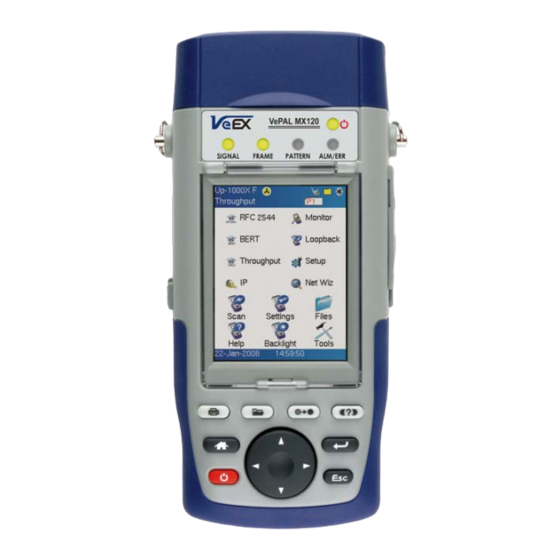
1.0 Product Introduction VeEX™ MX100 and MX120 Ethernet Expert test sets are next generation of Metro and Carrier Ethernet field test equipment for Ethernet Networks. The units are lightweight, rugged and weather resistant, and feature Gigabit Ethernet and Fast Ethernet test ports complete with advanced Triple Play verification capabilities. - Page 7 MX100/120 e-Manual D07-00-004 Rev A04 Page 7 of 115 Go back to top MX100 Introduction: The MX100 is part of the MX product family and is configured for; Single port operation Single Copper port 10/100/1000Base-T Single Fiber port 1000Base-X Test Applications: When the unit is operating in any of the physical ports above, each port is enabled to run the same test application.
-
Page 8: About This User Manual
(c) Copyright 2006-2007 VeEX Inc. All rights reserved. VeEX, VePAL are registered trademarks of VeEX Inc and/or its affiliates in the the USA and certain other countries. All trademarks or registered trademarks are the property of their respective companies. -
Page 9: Safety Information
Page 9 of 115 This device uses software either developed by VeEX Inc or licensed by VeEX Inc from third parties and is the confidential and proprietary of VeEX Inc. The software is protected by copyright and contains trade secrets of VeEX Inc or VeEX's licensors. The purchaser of this device agrees that it has received a license solely to use the software as embedded in the device, and the purchaser is prohibited from copying, reverse engineering, decompiling, or disassembling the software. -
Page 10: Touch-Screen Display
MX100/120 e-Manual D07-00-004 Rev A04 Page 10 of 115 Power key: The unit is powered on and off from the red key on the keypad. The button is recessed to prevent accidental power on. Press the key for 3-5 seconds to turn the unit on. To turn off the unit, press the power key for at least 2 seconds. -
Page 11: Connectors And Panels
MX100/120 e-Manual D07-00-004 Rev A04 Page 11 of 115 Go back to top 4.4 Connectors and Panels The connector panels are located at the top and the side of the unit. 4.4.1 Test Ports: MX100 Test Interfaces The MX100 is equipped with the following interfaces; Electrical Interface Single 10/100/1000Base-T Port, RJ45 connector, IEEE 802.3 compliant A green LED on the RJ45 connector flashes when there is activity on the network. - Page 12 MX100/120 e-Manual D07-00-004 Rev A04 Page 12 of 115 Go back to top MX120 Test Interfaces The MX120 is equipped with the following interfaces; Electrical Ethernet Interfaces Dual 10/100/1000Base-T Ports, RJ45 connector, IEEE 802.3 compliant A green LED on the RJ45 connector flashes when there is activity on the network. The green LED is On when there is a valid Ethernet link with the network and off when there is no link.
-
Page 13: Utility Ports
MX100/120 e-Manual D07-00-004 Rev A04 Page 13 of 115 Go back to top 4.4.2 Utility Ports The Ethernet and USB ports are located on the left and right side of the unit. RJ45, 10/100Base-T port: To access the Ethernet management port, remove the protective rubber cover on the right hand side of the unit to expose the connector. -
Page 14: Leds
MX100/120 e-Manual D07-00-004 Rev A04 Page 14 of 115 Go back to top 4.5 LEDs The MX100 and MX120 test sets are equipped with the following LEDs; Power LED: A single LED indicates the power state of the unit. The LED is off when the unit is powered off. The LED is green when the unit is powered on. -
Page 15: Home Screen And Menu
MX100/120 e-Manual D07-00-004 Rev A04 Page 15 of 115 Go back to top 5.0 Home Screen and Menu The Home menu can be accessed at anytime during operation by pressing the Home key on the rubber keypad. 5.1 Screen Layout The screen is divided into two presentation areas: Top: Test Applications specific to the MX100 and MX120;... -
Page 16: Actions Menu
MX100/120 e-Manual D07-00-004 Rev A04 Page 16 of 115 battery status If running on battery. File icon - Indicates File Storage. Tap icon to view memory capacity used Bluetooth icon - Future option (Bluetooth is not supported currently) IP icon - Indicates status of IP connection on either test or management port. Green indicates a valid IP connection while Red indicates no IP connection Open / Close icon - Open or Closes pull down menu and action bar. -
Page 17: Setup
MX100/120 e-Manual D07-00-004 Rev A04 Page 17 of 115 Go back to top 6.0 Setup Test port/s and network settings are required prior to performing any measurements or applications. 6.1 Port setup Port setup or the test interface configurations are accessed via the Setup menu located on the Home page. The user selects the operation mode and the interface/s that will be used to carry out tests. - Page 18 MX100/120 e-Manual D07-00-004 Rev A04 Page 18 of 115 MX120 Single Port selections; Single Copper port 10/100/1000 Base-T Single Copper port 10/100 to 100 Base-FX Single Fiber port 1000 Base-X MX120 Dual Port selections; Dual Copper port 10/100/1000 Base-T (P1 & P2 Copper) Dual Fiber port 1000 Base-X (P1 &...
-
Page 19: Port Status
MX100/120 e-Manual D07-00-004 Rev A04 Page 19 of 115 MX100/120 Copper Port MX100/120 Copper Port Advertisement Selection User Defined Selections Speed - Only available when auto-negotiation is off. Select from 10Mbps, 100Mbps, or 1000Mbps when the 10/100/1000T port is selected. 1000Mbps/1Gbps is fixed when the 1000Bse-X port is selected. Duplex - Only available when auto-negotiation is off for the 10/100/1000T port. -
Page 20: Laser Activation
MX100/120 e-Manual D07-00-004 Rev A04 Page 20 of 115 Go back to top 6.3 Laser Activation LASER On/Off Operation - When the 1000Base-X port/s is/are selected, the top pull down menu appears in the Setup/Port screen. From this pull down menu the user is able turn the LASER on or off. The LASER may also be turned on/off from any of the following application menus;... -
Page 21: Measurement Settings
MX100/120 e-Manual D07-00-004 Rev A04 Page 21 of 115 MX100/120 Profile Selection MX100/120 Profile View Go back to top 6.5 Measurement Settings Measurement Tab: The measurement and event log settings are configured in this screen. Mode: Manual, timed, or auto mode are available. Manual mode - User starts and stops the measurements manually. -
Page 22: Dual Port Navigation
MX100/120 e-Manual D07-00-004 Rev A04 Page 22 of 115 Event Log: Circular or Blocked. Up to 1000 event logs can be stored. Circular - only the latest events will be stored if there are over 1000 event logs. The oldest event will be deleted so that the new event can be added. - Page 23 MX100/120 e-Manual D07-00-004 Rev A04 Page 23 of 115 The same navigation principle that is applied in the Home/Setup menu (shown above), applies when the test set is being operated in any of the test applications (BERT, RFC 2544, Throughput, Loopback). An example of independent BERT applications running on port 1 and 2 are shown below.
-
Page 24: Test Applications
MX100/120 e-Manual D07-00-004 Rev A04 Page 24 of 115 Operating in dual port mode limits the same application to both ports, except for loopback. Note: Dual Port Testing Even if the application on each port is the same, ports can still be operated independently. This applies to both the configuration and the start/stop of the results. - Page 25 MX100/120 e-Manual D07-00-004 Rev A04 Page 25 of 115 Layer 3: Framed BERT (same as Layer 1 & 2 Framed) MAC Address: A default or user configured Media Access Control (MAC) address is added to the frame. This MAC address is used as the source MAC address for all streams. IP Address: A default or user configured IP address is added to the frame.
-
Page 26: Setup
MX100/120 e-Manual D07-00-004 Rev A04 Page 26 of 115 Go back to top 7.1.1 Setup The test layer, frame header, traffic profile, error injection, and control settings of the far end device (if applicable) must be configured prior to testing. 7.1.1.1 Header Settings BERT Profile: Load a previously configured test profile or create a new profile from existing settings. - Page 27 MX100/120 e-Manual D07-00-004 Rev A04 Page 27 of 115 Go back to top MAC, VLAN, MPLS, IP, and Test Pattern Configurations: To configure the MAC addresses, IP addresses, VLAN tag/s, MPLS tag/s, and test pattern, tap on the frame image displayed on the screen.
- Page 28 MX100/120 e-Manual D07-00-004 Rev A04 Page 28 of 115 Of the 4096 possible VIDs, a VID of 0 is used to identify priority frames and value 4095 (FFF) is reserved Maximum possible VLAN configurations are therefore set to 4094 VLAN Priority: Can be configured in the range 0 to 7 Set by the Priority Code Point (PCP), a 3-bit field which refers to the IEEE 802.1p priority.
- Page 29 MX100/120 e-Manual D07-00-004 Rev A04 Page 29 of 115 Note: This field is three bits in length and maps directly to IP Precedence TOS bits to provide class of service (COS). S-bit: Can be configured 0 or 1 Note; The S field is one bit in length and is used for stacking labels. This is important as it is used to indicate the last label in the label stack.
- Page 30 MX100/120 e-Manual D07-00-004 Rev A04 Page 30 of 115 Go back to top Data Tab: User selects a test pattern that will be encapsulated in the Ethernet frame payload (for framed mode). Depending on the test layer, different test pattern options are available; Layer 1 test patterns CRPAT - Compliant Random Pattern provides broad spectral content and minimal peaking for the measurement of jitter at component or system level.
- Page 31 MX100/120 e-Manual D07-00-004 Rev A04 Page 31 of 115 2^23 -1 (8 388 607 bit pattern primarily intended for error and jitter measurements at bit rates of 34 368 and 139 264 kbit/s) 2^15 -1 (32 767 bit pattern primarily intended for error and jitter measurements at bit rates of 1544, 2048, 6312, 8448, 32 064 and 44 736 kbit/s 2^11 -1 (2047 bit pattern primarily intended for error and jitter measurements on circuits operating at bit rates of 64 kbit/s and N ´...
- Page 32 MX100/120 e-Manual D07-00-004 Rev A04 Page 32 of 115 Go back to top 7.1.1.2 Traffic Settings Traffic tab: The user configures the traffic profile for the stream, including traffic flow, frame size, frame type, and transmit rate. Traffic Flow: Select from the following traffic flows: Constant - the selected frame is transmitted continuously according to the selected bandwidth %.
- Page 33 MX100/120 e-Manual D07-00-004 Rev A04 Page 33 of 115 Note: Frame Size Limitations Layer 1 framed mode - Frame size configuration is not available. Layer 1 unframed mode - Traffic profile is constant at 100% bandwidth. Go back to top 7.1.1.3 Error Injection Error injection can only be performed during testing.
- Page 34 MX100/120 e-Manual D07-00-004 Rev A04 Page 34 of 115 Note: Error Injection Once a test is running, error injection can be enabled by selection the “Error Injection ” icon from the action pull down menu at the top of the screen. Press the “error inject” button to start injecting errors. Go back to top 7.1.1.4 Control Settings In the Control settings tab, the user configures the loop-up and loop-down commands necessary to control a far end unit.
- Page 35 MX100/120 e-Manual D07-00-004 Rev A04 Page 35 of 115 Note: MX Discover Feature - If the local and remote test sets are on the same IP subnet, the MX Discover feature can be used - Automatically discover the far end test unit by pressing the Discover button - Once discovered, select the remote unit and send a loop up command - No manual configuration of the IP address is needed, since these are populated automatically Go back to top...
-
Page 36: Errors
MX100/120 e-Manual D07-00-004 Rev A04 Page 36 of 115 7.1.1.5 Starting/Stopping a BERT Once all the necessary configurations have been completed, user can start the test by selecting Start from the top right corner action pull down menu (green arrow pointing down). Once selected, the test will start immediately and the icon will change to a Stop indication. -
Page 37: Events
MX100/120 e-Manual D07-00-004 Rev A04 Page 37 of 115 BERT Results - Summary BERT Results - Errors Go back to top 7.1.2.3 Events Events tab: A time stamped record or log of anomalies, alarms, test status (start/stop) and test application are displayed. Go back to top 7.1.2.4 Alarms Alarms tab: The following Alarms (Current and Total) are displayed;... -
Page 38: Traffic
MX100/120 e-Manual D07-00-004 Rev A04 Page 38 of 115 Go back to top 7.1.2.5 Traffic Traffic tab: The following Traffic statistics are displayed; Frame Type - Test and non-test frames Traffic type - Layer 2 and Layer 3 Unicast, Broadcast and Multicast frame percentage Frame size distribution Pause frames Frames tab: The following Frame distribution statistics are displayed in count (#) and percentage (%);... - Page 39 MX100/120 e-Manual D07-00-004 Rev A04 Page 39 of 115 Go back to top Traffic Type tab: The following Traffic distribution statistics are displayed in Count (#) and Percentage (%); Layer 2 Unicast frames - number of Unicast frames received without FCS errors. Layer 2 Broadcast frames - number of Broadcast frames received without FCS errors.
-
Page 40: Rates
MX100/120 e-Manual D07-00-004 Rev A04 Page 40 of 115 Go back to top 7.1.2.6 Rates Rates tab: Rate statistics are displayed graphically and in tabular format; Frame rate in Frames per second (FPS) - number of received frames (including bad frames, Broadcast frames and Multicast frames) Data rate in Mbps - received data rate expressed in Mbps. -
Page 41: Saving Bert Results
MX100/120 e-Manual D07-00-004 Rev A04 Page 41 of 115 Minimum Maximum Variation (Current) BERT Results - Delay Go back to top 7.1.2.8 Saving BERT Results Once the test is completed, results can be saved by pressing the save function key on the keypad. The results will be saved and named automatically. -
Page 42: Setup
MX100/120 e-Manual D07-00-004 Rev A04 Page 42 of 115 7.2.1 Setup Unless otherwise noted, the Header and related setups are identical to the setups described in the BERT Test Application above. A summary of the RFC2544 setup options are outlined below. 7.2.1.1 Header Settings BERT Profile: Load a previously configured test profile or create a new profile from existing settings. -
Page 43: Frame Settings
86DD (Internet Protocol, Version 6 (IPv6)) - Future Release Data Tab: No payload selection is possible. The payload area is populated with a VeEX signature field and other proprietary data. RX Filter Tab: Depending on test layer, allows the user to filter streams by;... -
Page 44: Threshold Settings
MX100/120 e-Manual D07-00-004 Rev A04 Page 44 of 115 To add additional test frames, tap the 'Add Frame' button. Enter the frame size using the numeric keypad and click apply. Press the back button to return to the frames screen. The new custom frame size is displayed - it can be enabled or disabled as needed. -
Page 45: Throughput, Latency, Frame Loss, And Burst Settings
MX100/120 e-Manual D07-00-004 Rev A04 Page 45 of 115 Go back to top 7.2.1.4 Throughput, Latency, Frame Loss, and Burst Settings The RFC 2544 test suite allows the user to run all of the four tests, one of the four tests, or a combination of any of the four tests. The user simply has to enable/disable which tests to perform by checking/unchecking a selection box in the respective tab for each test. - Page 46 MX100/120 e-Manual D07-00-004 Rev A04 Page 46 of 115 Note: Control Mode Depending on the Control Mode selected (e.g. Asymmetric mode), test settings for upstream and downstream are also displayed Go back to top Latency tab: User configures; Test: Throughput Rate or Custom Rate. The default value is throughput. Throughput rate - latency test will be performed at the throughput rate found for each of the tested frame sizes.
- Page 47 MX100/120 e-Manual D07-00-004 Rev A04 Page 47 of 115 Go back to top Frame Loss tab: Max Rate: Up to 100% of the negotiated line rate. The default value is 100%. This is the maximum transmit rate to perform the frame loss test for each test frame size. The user may configure this rate as a % of the total line rate or in Mbps.
-
Page 48: Control Settings
MX100/120 e-Manual D07-00-004 Rev A04 Page 48 of 115 Note: Control Mode Depending on the Control Mode selected (e.g. Asymmetric mode), test settings for upstream and downstream are also displayed Go back to top Burst (Back-to-Back) tab: Max Rate: The default value is 100%. In the burst test, frames are always transmitted at the maximum rate for a given minimum and maximum burst duration. - Page 49 MX100/120 e-Manual D07-00-004 Rev A04 Page 49 of 115 information to the remote MX120 via the line under test. Upon completion, the remote MX120 transfers the test results back to the local MX120, enabling the user to read the results for both directions of the link on the local unit. The dual-port capability of the MX120 allows the user to test two links simultaneously.
-
Page 50: Results
MX100/120 e-Manual D07-00-004 Rev A04 Page 50 of 115 Far End Unit in Manual Loopback Mode: If the far end unit (another MX) is already in a manual loopback mode, the user must make sure that the control settings mode are set to manual. Do not send a loop up command, since it is not necessary. Once the correct control settings are configured, the user can start the test The selected tests will run automatically. -
Page 51: Throughput
MX100/120 e-Manual D07-00-004 Rev A04 Page 51 of 115 Go back to top 7.2.2.2 Throughput Throughput results are displayed in the following formats; Graphical Summary table Test log table RFC Results - Throughput RFC Results - Throughput Test RFC Results - Throughput Graph Summary Go back to top 7.2.2.3 Latency... -
Page 52: Frame Loss
MX100/120 e-Manual D07-00-004 Rev A04 Page 52 of 115 Graphical Summary table Test log - Byte Size, Latency (ms), Rate (%) and Status (Pass or Fail) RFC Results - Latency Summary RFC Results - Latency Graph RFC Results - Latency Test Log Go back to top 7.2.2.4 Frame Loss Frame loss results are displayed in the following formats;... -
Page 53: Burstability
MX100/120 e-Manual D07-00-004 Rev A04 Page 53 of 115 Go back to top 7.2.2.5 Burst Burstability (back-back) results are displayed in the following formats; Summary table Test log table RFC Results - Burstability Summary RFC Results - Burstability Test Log Go back to top 7.2.2.6 Saving RFC 2544 Results Once the test has been stopped the results can be saved by pressing the save key on the keypad. -
Page 54: Setup
MX100/120 e-Manual D07-00-004 Rev A04 Page 54 of 115 RFC Results - Storage RFC Results - File Explorer Go back to top 7.3 Throughput Testing (Multiple Streams) Overview: The throughput application (or the multiple streams application) performs the following measurements: throughput performance, frame loss analysis, delay analysis, frame/packet arrival analysis, received traffic type analysis, and received traffic frame size analysis. - Page 55 MX100/120 e-Manual D07-00-004 Rev A04 Page 55 of 115 # of Streams: From 1 to 8 streams. Pressing the zoom function, displays the Bandwidth allocated per Stream: Note: The total bandwidth for all streams cannot exceed 100%. Throughput Setup - General Throughput Setup - Stream BW Overview Go back to top 7.3.1.2 Control...
- Page 56 MX100/120 e-Manual D07-00-004 Rev A04 Page 56 of 115 purchased. MAC, VLAN, MPLS, and IP: To configure the MAC addresses, VLAN ID/priority, MPLS label/CoS/etc, IP addresses and header, tap on the 3-D image of the frame on the screen. This will bring you to the configuration screens for all the header fields.
-
Page 57: Traffic Settings (Individual Streams)
MX100/120 e-Manual D07-00-004 Rev A04 Page 57 of 115 Note: Multiple Streams All streams are configured for the same test layer - if layer 2 is selected, then all streams will be layer 2 traffic. Throughput - Header Summary Stream #1 Throughput - MAC Setup Stream #1 Note: Multiple Streams - MAC/IP address setups - If all streams are going to the same far end unit, then the MAC/IP destination addresses must be the same... -
Page 58: Error Injection Settings (Individual Streams)
MX100/120 e-Manual D07-00-004 Rev A04 Page 58 of 115 transmit rate. If the same traffic type applies to all streams, apply this profile to all streams using the Apply to ALL button Frame Size: Enter the frame size when a Layer 2 or Layer 3 BERT is selected. Frame size configuration is not available for Layer 1 BERT. -
Page 59: Starting/Stopping A Throughput Test
MX100/120 e-Manual D07-00-004 Rev A04 Page 59 of 115 Go back to top 7.3.1.6 Starting/Stopping a Throughput (Multiple Streams) Test Once all the necessary configurations have been made, the user can now start the Throughput test. The following are three scenarios of how to prepare and start the unit for Throughput testing. Note: If the testing on the fiber ports, make sure the LASER is turned On before starting the test. -
Page 60: Results
MX100/120 e-Manual D07-00-004 Rev A04 Page 60 of 115 7.3.2 Throughput Results 7.3.2.1 Viewing Test Results (Individual and Multiple Streams) When the test is first started, the screen automatically changes to the Global/Aggregate results screen. Go back to top 7.3.2.2 Global Results The Aggregate screen displays;... - Page 61 MX100/120 e-Manual D07-00-004 Rev A04 Page 61 of 115 The Global 'Alarms' screen displays the Current and Total alarm count of all streams; LOS Synchronization in ms Service Disruption statistics in ms Throughput Results - Global Errors Throughput Results - Global Alarms Go back to top The Global 'Traffic' screen displays;...
- Page 62 MX100/120 e-Manual D07-00-004 Rev A04 Page 62 of 115 7.3.2.3 Individual Stream Results In the 'Per Stream' tab the following measurements are available; Summary - Framed rate, data rate, # of bytes, total # of frames associated with each stream Errors - Errors associated with each stream Events - Events associated with each stream Traffic - Traffic statistics associated with each stream...
- Page 63 MX100/120 e-Manual D07-00-004 Rev A04 Page 63 of 115 Go back to top The Per Stream 'Events' screen displays a Date and Time stamped record of bit errors, alarms and other anomalies pertaining to each stream. The Per Stream 'Delay' screen displays the frame delay information pertaining to each stream. Throughput Results - Events per Stream Throughput Results - Delay per Stream Go back to top...
- Page 64 MX100/120 e-Manual D07-00-004 Rev A04 Page 64 of 115 Go back to top The Per Stream 'Rate' screen displays the frame rate and data rate pertaining to each stream. Tapping the zoom icon displays the rate details applicable to that stream Throughput Results - Rates Stream #1 Throughput Results - Rates Stream #2 Rate Details Stream #1...
- Page 65 MX100/120 e-Manual D07-00-004 Rev A04 Page 65 of 115 Go back to top 7.3.2.4 Saving Throughput (Multiple Streams) Results Only once the test has been stopped, can the results be saved by pressing the save function key on the VePAL’s keypad If the measurement is not stopped, a pop-up message will appear warning the user.
-
Page 66: Setup
MX100/120 e-Manual D07-00-004 Rev A04 Page 66 of 115 The Pass Through functionality allows; In-line traffic monitoring in both directions Long or short term network monitoring for troubleshooting network traffic problems Isolate network problems to the customer network or the service provider/operator network Monitor traffic between 1000Base-X links or 10/100/1000T links Pass through monitor operation Pass Through Monitor Copper 1GE... -
Page 67: Alarms
MX100/120 e-Manual D07-00-004 Rev A04 Page 67 of 115 Utilization in % CRC error count Service Disruption in ms Optical Power level in dBm (1000Base-X connections only) Once the cable/interface connections are in place, and the thresholds have been set, select and press Start from the pull down menu. -
Page 68: Events And Status
MX100/120 e-Manual D07-00-004 Rev A04 Page 68 of 115 Go back to top 7.4.2.3 Events and Status A time stamped record or log of anomalies, alarms, test status (start/stop) and test application are displayed. When Thresholds are enabled, a Pass or Fail value and status is displayed for each of the following parameters; Utilization % CRC Errors count Service Disruption in ms... - Page 69 MX100/120 e-Manual D07-00-004 Rev A04 Page 69 of 115 Unicast frames - number of Unicast frames received without FCS errors. Broadcast frames - number of Broadcast frames received without FCS errors. Broadcast frames have a MAC address equal to FF-FF-FF-FF-FF-FF. Multicast frames - number of Multicast frames received without FCS errors.
-
Page 70: Delay And Rates
MX100/120 e-Manual D07-00-004 Rev A04 Page 70 of 115 Go back to top 7.4.2.5 Delay and Rates Delay: Frame arrival statistics are displayed in tabular format; Current Minimum Maximum Variation (Current Rates: Rate statistics are displayed in tabular format; Frame rate in Frames per second (FPS) Current - number of received frames (including bad frames, Broadcast frames and Multicast frames) Minimum Maximum... -
Page 71: Port Selection
MX100/120 e-Manual D07-00-004 Rev A04 Page 71 of 115 Go back to top 7.4.2.6 Port Selection To view Port 1 and Port 2 results, select "P1" and "P2" respectively to switch between ports. Port Selection - Monitor Mode Go back to top... -
Page 72: Ip Tools
MX100/120 e-Manual D07-00-004 Rev A04 Page 72 of 115 7.5 Loopback The Loopback application in the main menu allows the user to establish a manual loopback on the test set. The loopback function is used when an end-to-end test needs to be performed with one of the test partners in software loopback mode. The Loopback function will loopback the incoming traffic to the test set back into the network under test. -
Page 73: Ip Setup
MX100/120 e-Manual D07-00-004 Rev A04 Page 73 of 115 Go back to top 8.1.1 IP Setup Enter a Static IP address or use DHCP to connect to the network. DHCP mode - an IP address will be automatically assigned to the test set. Static mode - user is required to enter a Local IP, Subnet, Gateway, and DNS IP (if the DNS server option is turned on). -
Page 74: Ip Status
MX100/120 e-Manual D07-00-004 Rev A04 Page 74 of 115 Go back to top 8.1.2 IP Status Status tab: IP Connection Status: Ensure the Status is PASS before continuing with any IP tests If the connection fails, go back to the setup screen to verify that the parameters are entered correctly Ensure that the Ethernet cable is connected properly before trying to reconnect Check the status LED on the Ethernet connector (on the right side of the unit) to look for port and network activity IP Status - DHCP mode... -
Page 75: Ping Test
MX100/120 e-Manual D07-00-004 Rev A04 Page 75 of 115 An IP test will verify that the IP network is configured properly and connected to the Internet. Depending on the IP options purchased, the following tests are possible; 8.2.1 Ping Test PING is a popular computer network tool used to test whether a particular host is reachable across an IP network. -
Page 76: Ftp Test
MX100/120 e-Manual D07-00-004 Rev A04 Page 76 of 115 Trace Route setup: The following setup selections are available - Once parameters are configured, click ‘Trace’ to start. Profile - Recall a trace route pfile or create a new test Destination - Enter the IP address or URL of the network device to be detected. Time-out - Enter the maximum time allowed between an ICMP echo and response at each hop Max Hop - Enter the maximum number of network devices the packet is allowed to transit. -
Page 77: Web Test
MX100/120 e-Manual D07-00-004 Rev A04 Page 77 of 115 Pass or Fail status Time to login into Rx server (Download) Data transfer in Mbps Total Transfer time Average Throughput according to the download or upload. FTP Download Setup FTP Download Result Go back to top 8.2.4 Web Test Web Test is used to verify that the internet is properly provisioned at the service point. -
Page 78: Web Browser
MX100/120 e-Manual D07-00-004 Rev A04 Page 78 of 115 Go back to top 8.2.5 Web Browser Select Browser from Web Mode Enter or select the desired IP address or URL destination, and encoding, and then press ‘Start.’ Note: The screen will turn blank while launching the spider web browser engine. Web Browser Setup Web Browser mode The web page is divided into quadrants. -
Page 79: Arp Wiz
MX100/120 e-Manual D07-00-004 Rev A04 Page 79 of 115 Go back to top 8.2.6 ARP Wiz ARP Wiz uses the Address Resolution Protocol (ARP) to verify the status of each IP address in a user selectable IP range. ARP is the standard method for finding a host's hardware address when only its network layer address is known. -
Page 80: Net Wiz
MX100/120 e-Manual D07-00-004 Rev A04 Page 80 of 115 Note: ARP The ARP protocol only works within the same subnet as the IP address provided to the test set in IP Status. Go back to top 8.3 Net Wiz The Net Wiz function allows you to test the Ethernet cable and associated network environment. A typical application is shown below;... -
Page 81: Status
MX100/120 e-Manual D07-00-004 Rev A04 Page 81 of 115 Netwiz Test functionalities include; Cable Analysis with distance to switch with MDI mode (Straight or Crossover) to fault, type of fault (Open, Short, Impedance Mismatch) Analyze the network and automatically report Stations Routers/Gateway Printers... -
Page 82: Wifi Wiz
MX100/120 e-Manual D07-00-004 Rev A04 Page 82 of 115 Networks tab indicates; Number of IP Subnets, Hosts, Domain, and Named Hosts Found. Netwiz - Discovery Summary Netwiz - Networks Discovery Discovery Result: Devices tab indicates; Total number of devices found Number of devices i.e. -
Page 83: Setup
MX100/120 e-Manual D07-00-004 Rev A04 Page 83 of 115 Typical WiFi Wiz Application The WiFi Wiz function supports; WEP Encryption Scanning SSID broadcasting and report Signal Strength Mode (AP, IF) and Security IP Connection and Ping Test Go back to top 8.4.1 Setup Plug the WiFi adaptor into the USB port. -
Page 84: Connection Status
MX100/120 e-Manual D07-00-004 Rev A04 Page 84 of 115 Scan - Tap on the Scan tab once the test set has detected the wireless USB adapter. Press Scan on the bottom to start scanning the site. When scan is completed, the test set will show the number of SSIDs, Channels, and the number of SSiDs in Infrastructures mode and Ad-Hoc mode. -
Page 85: Ping Test
MX100/120 e-Manual D07-00-004 Rev A04 Page 85 of 115 Note: Signal versus Link Quality Link quality - Fundamentally, the best way to measure link quality is to derive the Signal to Noise Ratio (SNR) of the desired received signal. For that to happen, a demodulator in the receive chain needs to provide information about the confidence of the detected symbol - also known as soft detection. -
Page 86: Voip Testing
MX100/120 e-Manual D07-00-004 Rev A04 Page 86 of 115 Go back to top 8.5 VoIP Testing 8.5.1 VoIP Check Go back to top 8.5.2 VoIP Expert Setup: Select the VoIP tab to proceed with VoIP Expert setup. There are three modes or applications; Client - To use the test set as a Client, the user needs to input the Server’s IP address and set a Test Duration. - Page 87 MX100/120 e-Manual D07-00-004 Rev A04 Page 87 of 115 the file. LOSS - Packet Loss DUP - Duplicate Packet DV - Delay Variation (DV) VoIP Expert Status VoIP Expert Status File Transfer Downstream File Transfer Upstream Go back to top Client Status: There are 3 stages in Client mode: Upstream - Stream the voice file to the Server.
- Page 88 MX100/120 e-Manual D07-00-004 Rev A04 Page 88 of 115 Go back to top MOS/R tab indicates; The Mean Opinion Score (MOS) and R-factor measurements are performed by a Telchemy™ VQmon® VoIP quality measurement engine which is integrated into the test set. The VQmon/SA feature supports; Listening and conversational quality metrics MOS scores and R factors Detailed packet/RTP statistics...
-
Page 89: Voip Call Expert
MX100/120 e-Manual D07-00-004 Rev A04 Page 89 of 115 that may affect the conversation Transmission Quality - Refers to the quality of the network connection used to carry the voice signal. Packets tab indicates; Analysis on packet loss Duplicated packets Out of sequence packets Packet rate Packet jitter... - Page 90 Codec - select between G.711A, G.711U, G.728 or G.729 Headphone - When the user turns on the headphone selection, an information box appears prompting you to plug-in the VeEX USB headphone adaptor. Ensure the headphone USB adapter is properly connected to the test set before pressing ‘OK’...
- Page 91 MX100/120 e-Manual D07-00-004 Rev A04 Page 91 of 115 VoIP Call Expert VoIP Call Expert Registration progress Registration complete Go back to top 8.5.3.3 Call Status To place a call; First enter a destination IP address - The address can be a phone number (phone number@sipserver) or an alias (bob@sipserver) Press ‘Call’...
-
Page 92: Iptv Testing
MX100/120 e-Manual D07-00-004 Rev A04 Page 92 of 115 Receive Call Status: An information box appears on screen when there is an incoming call The user can choose to accept or to decline the call Once connected, you can use the USB headphone adapter to talk and listen VoIP Call Expert VoIP Call Expert Incoming call message... -
Page 93: Setup
MX100/120 e-Manual D07-00-004 Rev A04 Page 93 of 115 8.6.1 Setup Channel Table - Select the IPTV channel table to test. The IPTV channel table can be configured manually on the test set using the Editor function. Alternatively, the IPTV channel table can be created using the ReVeal LX software which can subsequently be downloaded onto the test set. - Page 94 MX100/120 e-Manual D07-00-004 Rev A04 Page 94 of 115 Video streams typically consume more bandwidth than audio streams, which in turn use more bandwidth than data streams. In this manual, MPEG-2 refers to the video transport stream defined in IEC13818 standard and not any compression technology used payload or transport packet.
- Page 95 MX100/120 e-Manual D07-00-004 Rev A04 Page 95 of 115 IPTV Result Video (Page #2) - displays the Stream Rate results; Table provides individual bit rate statistics for each stream; Total is the total number of bytes related to the Video, Audio and Data payloads Video is the number of packets classified as video packets Audio is the number of packets classified as audio packets Data is the number of packets classified as data packets...
- Page 96 MX100/120 e-Manual D07-00-004 Rev A04 Page 96 of 115 Go back to top IPTV Result Video (Page #4) - displays the Quality of Service (QOS) results; PCR Clock - Presence of 27MHz Program Clock Reference PCR Jitter - PCR deviation in (ms) MPEG Packet Loss - continuity error (%) Latency - the time to complete a program change measured in milliseconds (ms) IPTV Video Stream QOS &...
- Page 97 MX100/120 e-Manual D07-00-004 Rev A04 Page 97 of 115 Go back to top IPTV Result Video (Page #6) - displays the Media Delivery Index (MDI) results; MDI (Media Delivery Index) - value in a ratio DF (Delay Factor) - Average, Minimum and Maximum values. Also defined as cumulative IP jitter, it represents the time it would take to drain an output buffer and ensure good video playback.
- Page 98 MX100/120 e-Manual D07-00-004 Rev A04 Page 98 of 115 Go back to top IPTV Result MAP: The MAP table provides a summary of the stream composition and the programming present. Str - Indicates stream number PID - Packet Identifier is a unique channel address identifier. PID enables identification and reconstruction of the programme and is used in conjunction with the Programme Service Identifier (PSI) packets.
- Page 99 MX100/120 e-Manual D07-00-004 Rev A04 Page 99 of 115 Status - OK, no packet, Fail Bandwidth - bandwidth associated with the stream IPTV Channel Scan IPTV Zapping Overview IGMP and Channel Zapping IGMP is a signaling protocol that enables each STB to obtain only the programming that the viewer is interested in watching, thus conserving bandwidth in the access network.
-
Page 100: Utilities
MX100/120 e-Manual D07-00-004 Rev A04 Page 100 of 115 Physical Layer and IPTV Protocol Stack Troubleshooting Concept Go back to top 9.0 Utilities 9.1 Help The Help menu provides access to this user manual which has also been stored in the instrument. All text is preserved however tables, application diagrams, screens shots and tables are omitted to save memory space. -
Page 101: Settings
MX100/120 e-Manual D07-00-004 Rev A04 Page 101 of 115 Go back to top 9.2 Settings This section provides settings for the global parameters of the test set. 9.2.1 About Provides information about the software version, serial number and MAC address of the unit. About Menu About Menu (Page #1) The About menu also allows the user to view installed options. -
Page 102: Screen
Calibrate the touch-screen when out of calibration. Screen Theme Screen Alignment Go back to top 9.2.3 Selftest This utility provides a complete diagnostic of the test set. The report can be exported and provided to VeEX Inc Customer Care Department. -
Page 103: Power
MX100/120 e-Manual D07-00-004 Rev A04 Page 103 of 115 Go back to top 9.2.4 Power This menu provides information about; Current power source detected Battery status including battery gauge. User selectable Auto-Off timer feature Note: Battery status can also be obtained by tapping the battery icon on the main screen Power Menu Battery Status Go back to top... - Page 104 MX100/120 e-Manual D07-00-004 Rev A04 Page 104 of 115 Go back to top 9.2.6 Global Settings This menu allows the user to select; Language: An alternative language for the user interface Units: Measurement system (English - feet or Metric - meter). Show Password: Hides/unhides Username and Password information associated with FTP and related IP functions Management Port: Sets LAN management port to Remote Control or IPTV mode Saving: Automatic or Advanced.
-
Page 105: Date And Time
MX100/120 e-Manual D07-00-004 Rev A04 Page 105 of 115 9.2.7 Date and Time This menu allows the user to set; Date and time Time zone - Daylight savings are automatically enabled in the utility. Date and Time Setting Time Zone Setting Go back to top 9.3 Files The MX100/120 saves the Files (Test results) in the unit's internal memory for recall and viewing. -
Page 106: File Transfer
MX100/120 e-Manual D07-00-004 Rev A04 Page 106 of 115 Go back to top 9.3.3 File Transfer The test result files are saved in a proprietary format. To archive, print or generate test reports, please export or transfer the files using one of the following methods. USB Memory Device via USB interface. -
Page 107: Ftp File Transfer
MX100/120 e-Manual D07-00-004 Rev A04 Page 107 of 115 Input a File/Path once the USB storage device is detected. A "File/Path" is the name of the folder where the files will be stored on the USB device. Press ‘Transfer’ to start the file transfer - An information box appears indicating the transfer is in progress. Press ‘OK’... - Page 108 MX100/120 e-Manual D07-00-004 Rev A04 Page 108 of 115 Enter a valid FTP server address, File/Path, Username, and Password. Once the server parameters are entered, click ‘Upload’ to start uploading the files. During the transfer, a % progress message appears in the file transfer window. Files - FTP Upload Setup FTP Upload Progress A "Transfer finished"...
-
Page 109: Profiles
MX100/120 e-Manual D07-00-004 Rev A04 Page 109 of 115 Profiles: Create, Edit and Manage Test Profiles Results: Download and Manage test results, generate Test Reports Software: Download software, upgrade test set, add options and check instrument configuration Tools: Remote Control the instrument (optional) ReVeal MX - Home Menu Go back to top 9.4.1 Profiles... -
Page 110: Results
MX100/120 e-Manual D07-00-004 Rev A04 Page 110 of 115 Go back to top 9.4.2 Results Results menu allows you to; Download Results Manage Results Create Reports Convert Results to PDF format Convert Results to CSV (Comma Separated Value) format Print Results to a selected printer ReVeal MX - Results Menu... -
Page 111: Software
Page 111 of 115 Go back to top 9.4.3 Software The Software menu allows you to; Download software from the VeEX website to upgrade the test set Enable or Disable software options Check test set configuration Upgrade test set software... -
Page 112: Tools
MX100/120 e-Manual D07-00-004 Rev A04 Page 112 of 115 Go back to top 9.4.4 Tools 9.4.4.1 Remote Control Launch ReVeal LX software on your PC to remote control the instrument. The test instrument must be connected to the PC via an IP connection. Select the remote control application located in the Tools menu. -
Page 113: Warranty And Software
Replace the hardware which prove to be defective provided that the products that the customer elects to replace is returned to VeEX Inc by the customer along with proof of purchase within thirty (30) days of the request by the customer, freight prepaid. -
Page 114: Product Specifications
(hardware, software, firmware and/or accessories) Revoking the warranty: VeEX Inc does not guarantee or warrant that the operation of the hardware, software or firmware will be uninterrupted or error-free. The warranty will not apply in any of the following cases: Improper or inadequate maintenance by the customer Damage due to software installed by the customer on the unit without prior authorization (written) from VeEX Inc. -
Page 115: About Veex
Go back to top 13.0 About VeEX VeEX Inc, the Verification EXperts, is an innovative designer and manufacturer of test and measurement solutions addressing numerous technologies. Global presence through a worldwide distribution channel provides uncompromised product support. Visit us online at www.veexinc.com...
Need help?
Do you have a question about the MX100 Series and is the answer not in the manual?
Questions and answers