Table of Contents
Advertisement
Quick Links
Advertisement
Table of Contents

Related Manuals for VeEX MTTplus-420


Summary of Contents for VeEX MTTplus-420
-
Page 2: Table Of Contents
Table of Contents 1.0 General Information 2.0 Safety Information 3.0 Introduction to MTTplus-420 3.1 MTTplus-420 Overview 3.2 What is GPON 3.3 Key Features 3.4 Specifications 4.0 Basic Operation 4.1 Connector Panels 5.0 Preparing for Operation 5.1 Equipment Check List 5.2 GPON ITU-T G.984 Test Standards 6.0 Optical Fiber Patch Cord Preparation... - Page 3 6.7.1 Preventing Inaccurate Reading 6.8 Fiberscope Platform Application 6.8.1 Connecting the Fiberscope 6.8.2 FiberScope Setup - Page 1 6.8.3 FiberScope Analyzer - Page 2 6.8.4 FiberScope Capture Screen 6.8.5 Results 6.8.5.1 HTML Report 6.8.6 Managing Fiberscope Results with File Manager 6.8.6.1 File Manager Filters 6.8.6.2 Backing up and Restoring Test Profiles and Results From USB...
- Page 4 9.2.4 BIP 9.2.5 RDI 9.2.6 REI 9.2.7 Corr FEC 9.2.8 Uncor FEC 10.0 GPON Rogue ONU Detection 11.0 GPON Wizard 12.0 Splitter Analysis 13.0 Distribution Analysis 14.0 Common Functions 15.0 Certifications and Declarations 16.0 About VeEX MTTplus-420_User_Manual_RevC00 Page 4 of 75...
- Page 5 APPENDIX A GPON DEFINITIONS APPENDIX B GPON ABBREVIATIONS AND ACRONYMS APPENDIX C PLOAM MESSAGES IN G.984 G-PON C.1 Activation Process Overview C.2 PLOAM Messages C.2.1 Upstream overhead Message: Downstream C.2.2 Extended_burst_length Message: Downstream C.2.3 Serial_number_ONU Message: Upstream C.2.4 Assign_ONU-ID Message: Downstream C.2.5 Ranging_time Message: Downstream C.2.6 Request_password Message (Downstream) and Password Message (Upstream)
- Page 6 C.2.19 Dying_gasp Message: Upstream C.2.20 Physical_equipment_error (PEE) Message: Both Directions C.2.21 PST (Protection Switch) Message: Both Directions C.2.22 Change_power_level Message: Downstream - Unicast or Broadcast C.2.23 PON-ID: Downstream (optional) C.2.24 Downstream (optional) C.2.25 Ranging_adjustment: Downstream (optional) Go back to top MTTplus-420_User_Manual_RevC00 Page 6 of 75...
-
Page 7: General Information
VeEX, Inc. or VeEX's licensors. The purchaser of this device and/or software, downloaded or embedded, agrees that it has received a license solely to use the software as embedded in the device and/or provided by VeEX Inc., and to use it solely as intended and described in this manual. - Page 8 Go back to top Go back to TOC 1.4 Documentation Conventions Icons used in this manual: Marks a helpful tip (action or method), which can save time and improve usability of the product. Provides important information needed to use this product and avoid missteps.
-
Page 9: Safety Information
Do not operate the instrument in the presence of flammable gases or fumes or any other combustible environment. VeEX Inc. assumes no liability for the customer's failure to comply with safety precautions and requirements. - Page 10 ESD: Electrostatic Discharge Sensitive Equipment Test modules could be affected by electrostatic discharge. To minimize the risk of damage when replacing or handling test modules, make sure to follow proper ESD procedures and dissipate any electrostatic charge from your body and tools and the use proper grounding gear. Perform all work at a workplace that is protected against electrostatic build-up and discharging.
-
Page 11: Mttplus-420 Overview
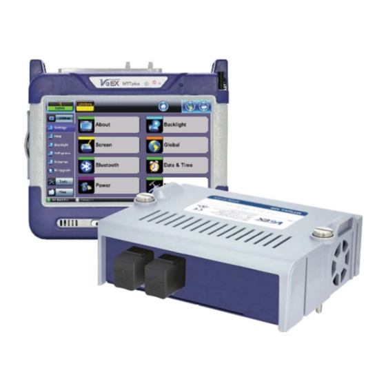
3.1 MTTplus-420 Overview The MTTplus-420 GPON test module for the VeEX® MTTplus platform is designed for ONT/ONU service activation and troubleshooting. It is only intended to be used at the customer site between the splitter and Optical Network Unit/Optical Network Terminal (ONU/ONT). -
Page 12: Specifications
2. Burst mode -15 to +5 dBm. 3. At 23°C, at 1310/1490 nm, using CW - 7 dBm source. The most recent product specifications can be found on the VeEX web site at www.veexinc.com Go back to top Go back to TOC... -
Page 13: Basic Operation
MTTplus host chassis, refer to the MTTplus Platform manual. 4.1 Connector Panels The MTTplus-420 module connector panel features an ONU port (To ONU) and an OLT port (To OLT). MTTplus-420 connector panel with ONU and OLT ports... -
Page 14: Preparing For Operation
Since the MTTplus-420 is only designed to be used between the splitter and ONT (Customer Site), we are only concerned about the ONT received power for the 1490nm signal and ONT launch power at 1310nm. 1490nm received power and 1310 launch power are both shown below... - Page 15 2.48 Gbps Downstream Direction 1490nm ONT/ONU Receive Power 1490nm OLT Launch Power (dBm) (dBm) Class Class Class Class Class Class Class Class Class Class Min Avg Power Max Avg Power 1.244 Gbps Upstream Direction 1310nm ONT/ONU Launch Power 1310 OLT Receive Power (dBm) (dBm) Class...
- Page 16 OLT and ONU communication defined in ITU G.984.3 standard NOTE 1 – OLT waits at least 750 μs for the ONU to process the message. NOTE 2 – ONU clears LOS/LOF error. NOTE 3 – ONU constructs the preamble and delimiter and sets pre-assigned delay. NOTE 4 –...
-
Page 17: Optical Fiber Patch Cord Preparation
6.0 Optical Fiber Patch Cord Preparation Dirt, dust, and other contaminants severely impact high-speed data transmission in optical fibers and dirty connector end-faces are often the number one cause of link failures. High insertion loss and/or high back reflection can result in transmission loss or high bit errors and poor BER. -
Page 18: Inspection
Cross-section-mode and multi-mode fiber zones Go back to top Go back to TOC 6.2 Inspection Whenever possible, inspect the fiber-optic connection (connectors, bulkheads, and test interfaces) with a fiber microscope. It is recommended to wear laser safety glasses when working with fiber-optic connections. Always check that the laser or transmitter is disconnected before cleaning the connector end faces. - Page 19 Optical fiber cleaning materials clockwise from left--isopropyl alcohol, lint free soft tissues, connector reel cleaners, and a ferrule cleaner Clean the connector end-face by rubbing it onto a lint-free wipe dampened with isopropyl alcohol Procedure 1. Dab the contaminated connector end-face with a wipe that has been dampened with isopropyl alcohol - the solvent will dissolve and remove contaminants that have dried and attached to the connector or fiber end-face.
-
Page 20: Best Practices
Using Compressed Air In some clean air situations, filtered air is acceptable for use, which is free of oil and moisture to remove debris and clean a fiber optic connection. However, unless very strict cleaning procedures are followed, air-driven contaminants can cause more problems. To use compressed air, hold the can upright. -
Page 21: Connectors
6.5 Connectors 6.5.1 Connectors Types GPON networks typically use SC type connectors. The preferred connector polish is the angled polish, SC/APC (Green), but the ultra-polished SC/UPC (Blue) can also be used. SC Connector SC officially stands for Subscriber Connector; however, some people believe that “Square Connector,” is the correct name. It is a general purpose push/pull style connector. -
Page 22: Fiber Patch Cords
Connector Polish and Performance UPC and APC back reflection UPC and APC return loss Typical Return loss values are: Polished Connector ~ -45dB Ultra-Polished Connector ~ -55dB Angled Polished Connector up to ~ -65dB Go back to top Go back to TOC 6.6 Fiber Patch Cords 900μm Patchcords... -
Page 23: Fiber Patch Cord
In a typical GPON network, a fiber is connected directly to the customer ONT/ONU. To test the GPON network, the fiber must be temporarily disconnected from the ONT/ONU and inserted into the MTTplus-420 OLT port. An additional fiber patch cord is then used to connect the MTTplus-420 ONU port to the ONT/ONU modem. -
Page 24: Inserting The Fiber
Standard color coding for jackets and boots (or connector shells) Go back to top Go back to TOC 6.7 Inserting the Fiber Carefully align the optical fiber connector to the port to avoid rubbing the fiber against the external part of the port or any other surface. If the interface of the connector has an alignment key, make sure to insert it correctly into the corresponding groove. -
Page 25: Fiberscope Platform Application
The OTDR Viewer application is used solely with the VeEX OPX-BOXe/OPX-BOX+ OTDR platform. This extends the capabilities of the VeEX test set as a post-market add-on option for fiber optics testing. The Optical Power Meter application (in Fiber Tools) works with a tethered FX4x/FX8x OPM/OLTS meter as an add-on fiber optics testing capability. -
Page 26: Fiberscope Setup
6.8.2 FiberScope Setup - Page 1 Fiberscope Setup menu Captured patch cord image files are saved within a folder directory. In the Setup tab, name each folder and file in the directory and select a save increment. Scope mode: Sets Fiber Scope connection method. Local: Direct USB connection via micro-B USB port and micro-B USB-to-USB Type A OTG cable for DI-1000, DI- 1000MPO, and DI-3000. -
Page 27: Fiberscope Analyzer
6.8.3 FiberScope Analyzer - Page 2 Fiberscope Setup menu - page 2 (Analyze connector profile selections) To begin analyzing fiber connectors: 1. Select the analysis profile from the Analysis parameters drop-down box on Page 2/2 of the Setup tab. The analysis profile is based on the fiber endface connector inspected, as well as applicable to MTP™/MPO (multi-fiber) connectors. -
Page 28: Fiberscope Capture Screen
6.8.4 FiberScope Capture Screen Real time video of the connector face. Red contours indicate scratches and defects. Page 1 of the capture screen displays a live image of the connector face and features analysis and freeze tools. Freeze / Resume: Stops the real time video to produce a viewable static image. Analysis On / OFF: Turn the Auto Analysis ON and OFF (software option). -
Page 29: Results
6.8.5 Results Saved files from Capture screen The results screen displays management options for saved results including uploading/downloading files from VeEX’s Fiberizer Cloud. The directory displays the location of stored files. Load: Select an image file and tap Load to load the image onto the Capture tab. -
Page 30: Html Report
Fiberizer Cloud Log-in 1. Tap on Modify > Settings. 2. Enter the username and password, then tap Check. If the message “Connection has been successfully verified…” does not display, recheck the username and password. 3. Tap Select to choose a project folder to upload files to and tap OK. 4. -
Page 31: File Manager Filters
6.8.6 Managing General Results with File Manager All results stored in the test set are displayed in the File Manager, located in Utilities > Files > Saved. When managing files, use the check box to select the desired file(s). File Manager menu The following file management options are available: View: View file Del: Delete... -
Page 32: Backing Up And Restoring Test Profiles And Results From Usb
Filtering for specific test types by tapping on the Test header filter+ icon Fiber inspection test results belong to Common Mode and Fiberscope Tests. Filter parameters can be combined. Filter Options To filter by header type, use the stylus to tap on the filter+ icon. -
Page 33: Optical Power Meter (Opm) Test Mode
7.0 Optical Power Meter (OPM) Test Mode OPM Summary Screen The MTTplus-420 starts up on the OPM Home menu. Refer to the MTTplus Platform manual for information on home screen test icons and menus common to all MTTplus modules. The OPM Home menu is described below. - Page 34 Signal Measurement Table Displays 1490nm and 1310nm signal level values as measured at the MTTplus-420’s location. OLT Loss is the difference between the transmitting signal from the OLT (TX) and the DS 1490nm signal level measured at the MTTplus-420 location.
-
Page 35: Optical Power Meter (Opm) Test Procedure
The History button resets the LEDs of past statuses. If any LED remains red, clean the patch cord connectors that will connect the MTTplus-420 to the ONU/ONT, the MTTplus-420 test ports (To ONU, To OLT), and the ONU/ONT ports. Refer to Inspection for information on inspecting and cleaning fiber connectors. - Page 36 60KM OPM Setup menu 3. Inspect and clean the MTTplus-420 test ports. Inspect and clean the fiber patch cord from the OLT and insert it into the MTT420-plus OLT test port. Warning: Never look directly into the beam of an active optical source as this may result in harmful eye damage from radiation exposure 4.
-
Page 37: Histogram And Olt Loss History
Once the ONU registration is complete, the MTTplus-420 then uses the bandwidth allocation information contained in the downstream frames in order to determine when the upstream burst from the ONU will occur and what data it will contain. Should the downstream frame become corrupted at this point, the upstream frame reception will also therefore be affected. -
Page 38: Advanced Mode
8.0 Advanced Mode Advanced Mode features advanced troubleshooting tests beyond basic signal level measurements. Further investigation may be required when the OPM test mode indicates good signal level and TCSync is good but network is generating alarm or errors. Advanced Results provides a summary screen of network status and reports system errors/alarms status. PLOAM and OMCI Decoder captures and decodes PLOAM and OMCI messages exchanged between the Optical Line Terminal (OLT) and ONT. -
Page 39: Advanced Setup
8.1 Advanced Setup Advanced Setup - Measurements tab Advanced Setup options include programming test duration/start time, PLOAM Decoder Filter options, and additional test management options. Measurements Select a Mode option to enable a test to run for a fixed duration and/or a delayed start. Mode: Manual, Timed, and Auto selections are available. -
Page 40: Advanced Results
Measurement Clock Source: Select the Measurement clock source used for Frequency measurement. Go back to top Go back to TOC 8.2 Advanced Results Advanced Results - Summary tab The Advanced Results menu displays additional Errors/Alarms and Event details. Summary The summary tab displays a summary of test results including DS/US signal levels, PON ID, and alarm statuses all on one screen. Go back to top Go back to TOC 8.2.1 Errors/Alarms Errors/Alarms tab showing summary of US/DS errors/alarms statuses... - Page 41 The Errors/Alarms tab brings up several pages showing error and alarm statuses. Page 1 provides an overview of all the Errors and Alarms applicable to the signal and network under test. The color of the page tab is normally blue; however, it will turn red when an alarm error condition has been detected or recorded. The soft LEDs have a tricolor function: Green: No error or alarm is present.
- Page 42 Histogram G-PON Histogram showing start and stop time of alarms/errors The Histogram tab displays a historical record of the Alarms and Errors recorded during the measurement interval. A separate page is available for down stream and upstream results . A graphical timeline on the horizontal axis indicates when the event occurred in seconds. Tap on the upper left and right arrows to scroll through the measurement period.
-
Page 43: Active Onu
Events Log Event Log showing start, stop, and error/alarm events The Event Log tab brings up a screen listing the Error and Alarm events recorded during a test. The events are presented in chronological sequence - number, type of event, start time, duration (alarms), and ratio/count (errors) are displayed. Go back to top Go back to TOC 8.3 Active ONU Active ONU lists all of the ONUs that have been activated by the OLT since the measurement was started/restarted from the OPM... -
Page 44: Ploam Decoder
ONU Disconnected The last ONU activated will be green. The last ONU activated Go back to top Go back to TOC 8.4 PLOAM Decoder MTTplus-420_User_Manual_RevC00 Page 44 of 75... - Page 45 PLOAM Decoder screen Physical Layer Operations, Administrations and Maintenance (PLOAM). Decoder displays upstream/downstream decoded PLOAM messages between the ONUs/ONTs and the OLT. Tap Clear to clear the list or tap on the screen to see additional message details. Refer to Appendix C for the activation process overview and a description of each PLOAM message.
-
Page 46: Troubleshooting Gpon Alarms/Errors
9.0 Troubleshooting GPON Alarms/Errors Alarms and performance monitoring encompasses mechanisms to detect link failure and monitor the health and performance of links. This clause does not cover such functions as station management, bandwidth allocation or provisioning functions. The flow chart illustrates OAM functions installed in the ONU and OLT. It also shows the Alarm notification signals between OLT and ONU. -
Page 47: Downstream Alarms/Errors
9.1 Downstream Alarm/Errors 9.1.1 LOS LOS means 1490nm Loss of Signal is detected. In an active GPON network, the 1490nm DS is always transmitting. LOS Troubleshooting 1. Verify GPON fiber is inserted in the To OLT test port. 2. Check the optical fiber. If the optical fiber is not connected properly, clean/inspect/reconnect the optical fiber again and make sure the fiber is connected correctly and securely. - Page 48 BIP Impact: BIP provides an approximate method for monitoring link quality at the bit error level. GPON downstream frame structure GPON upstream frame structure Go back to top Go back to TOC MTTplus-420_User_Manual_RevC00 Page 48 of 75...
-
Page 49: Corr Fec
LOS means 1310nm Loss of Signal is detected. In an active GPON network, the 1310nm US signal is bursty in transmission. LOS Troubleshooting 1. Verify the patchcord from ONU/ONT is connected to the MTTplus-420 ONT test port. 2. Check the patch cord. -
Page 50: Bip
LCDG IMPACT: Loss of frame (LOF) in the system and the ONT goes offline. Possible LCDG Causes: Optical fiber is faulty or ONT is faulty. Go back to top Go back to TOC 9.2.4 BIP Each GPON Transmission Convergence (GTC) upstream frame must contain physical layer overhead data (PLOu) which includes the physical layer overhead and three fields of data: Preamble and delimiter, BIP, ONU ID and real time ONU status report to OLT. -
Page 51: Gpon Rogue Onu Detection
10.0 GPON Rogue ONU Detection A GPON network comprises of an optical line terminal (OLT) that may typically interact with 32 optical network units (ONU) with a maximum of 128 ONUs. The OLT manages upstream communication by assigning a time slot for each active ONU in order to prevent transmission collision between active ONUs. -
Page 52: Gpon Wizard
11.0 GPON Wizard GPON Wizard is a function which guides the user through the process with on screen images to show how to connect the tester. 1. Tap on GPON Wizard. 2. Follow the instructions on screen and tap OK. 3. - Page 53 4. Follow on screen instructions and tap Next. MTTplus-420_User_Manual_RevC00 Page 53 of 75...
- Page 54 Once connected the status LED's will go from Red to Green. 5. Test complete, follow on-screen instructions 6. Tap Next Port to test the next port. MTTplus-420_User_Manual_RevC00 Page 54 of 75...
- Page 55 7. Add next port number. 8. Follow on screen instructions and tap Next. MTTplus-420_User_Manual_RevC00 Page 55 of 75...
- Page 56 Once connected the status LED's will go from Red to Green. 9. Test in progress MTTplus-420_User_Manual_RevC00 Page 56 of 75...
- Page 57 10. If testing more ports follow instructions above, if ending the test tap on Stop. 11. Save test results. MTTplus-420_User_Manual_RevC00 Page 57 of 75...
- Page 58 Go back to top Go back to TOC MTTplus-420_User_Manual_RevC00 Page 58 of 75...
-
Page 59: Splitter Analysis
12.0 Splitter Analysis 1. Tap on Splitter Analysis and enter the name of the cabinet, tap apply. Name the Cabinet 2. Select Panel Type and tap OK. MTTplus-420_User_Manual_RevC00 Page 59 of 75... - Page 60 Panel Type 3. Enter the Rack number, tap on start and follow the instructions. Parameter Parameter MTTplus-420_User_Manual_RevC00 Page 60 of 75...
- Page 61 4. Disconnect/Reconnect every patch cord connected on the splitter one by one. Parameter Tap on each square to view the S/N Meaning of characters L: Empty N: No S/N O: ONU S/N detected 5. Tap on Stop and the remaining cells will be filled with empty ("L"). Tap on Save to save the splitter analysis and generate a csv file.
-
Page 62: Distribution Analysis
13.0 Distribution Analysis 1. Tap on Distribution Analysis and enter the name of the cabinet, tap apply. Name the Cabinet 2. Select Panel Type and tap OK. MTTplus-420_User_Manual_RevC00 Page 62 of 75... - Page 63 Panel Type 3. Enter the Rack Number, tap on start and the follow the instructions. Parameter Parameter MTTplus-420_User_Manual_RevC00 Page 63 of 75...
- Page 64 4. Connect every port indicated in blue to the MTT420 ONU port. Parameter Tap on each square to view the S/N Meaning of characters L: Empty N: No S/N O: ONU S/N detected X: Position skipped 5. Tap on Stop and the remaining cells will be filled as empty (“L”). Tap on Save to save the distribution analysis and generate a csv file.
-
Page 65: Common Functions
14.0 Common Functions Refer to the MTTplus Platform manual for information on the following functions common to all MTTplus-series units: Tools: IP Tools Net Wiz WiFi Wiz Advanced Browser Utilities Settings Help Backlight VeEXpress R-Server Files Saved Manage Go back to top Go back to TOC MTTplus-420_User_Manual_RevC00 Page 65 of 75... -
Page 66: Certifications And Declarations
VeEX Inc. is committed to comply with RoHS and WEEE Directives to minimize the environmental impact of our products. For more information about RoHS as it relates to VeEX Inc, go to the VeEX web site at www.veexinc.com/RoHS. Go back to top Go back to TOC... -
Page 67: About Veex
With a blend of advanced technologies and vast technical expertise, VeEX products address all stages of network deployment, maintenance, field service turn-up, and integrate service verification features across copper, fiber optics, CATV/DOCSIS, mobile 4G/5G backhaul and fronthaul, next generation transport network, Fibre Channel, carrier &... -
Page 68: Appendix A Gpon Definitions
Appendix A GPON Definitions Activation: A set of distributed procedures executed by the OLT and the ONUs that allows an inactive ONU to join or resume operations on the PON. The activation process includes three phases: parameter learning, serial number acquisition, and ranging. Bandwidth allocation: An upstream transmission opportunity granted by the OLT for the duration of the specified time interval to the specified traffic-bearing entity within an ONU. - Page 69 Pre-assigned delay (PrD): The requisite delay that all the ONUs on the PON are required to use prior to completion of the ranging phase of the activation process. Quiet window: A time interval during which the OLT suppresses all the bandwidth allocations to the in-service ONUs in order to avoid collisions between their upstream transmissions and the transmission bursts from the ONUs that have just joined the PON and are undergoing the activation process.
-
Page 70: Appendix B Gpon Abbreviations And Acronyms
Appendix B GPON ABBREVIATIONS AND ACRONYMS AES - Advanced Encryption Standard Alloc-ID -Allocation Identifier ANI - Access Node Interface APS - Automatic Protection Switching BCH - Bose-Chaudhuri-Hocquengham BER - Bit Error Ratio BIP - Bit Interleaved Parity B-ISDN - Broadband Integrated Services Digital Network Blen - BWmap Length B-PON - Broadband Passive Optical Network BW - Bandwidth... - Page 71 PEE - Physical Equipment Error PHY - Physical Interface PIR - Peak Information Rate PLend - Payload Length downstream PLI - Payload Length Indicator PLOAM - Physical Layer OAM Operations, Administrations and Maintenance PLOAMd - Physical Layer OAM Operations, Administrations and Maintenance downstream PLOAMu - Physical Layer OAM Operations, Administrations and Maintenance upstream PLOu - Physical Layer Overhead upstream PLSu - Power Levelling Sequence upstream PMD - Physical Media Dependent PON - Passive Optical Network Port-ID - Port Identifier...
-
Page 72: Activation Process Overview
Appendix C PLOAM Messages In G.984 G-PON C.1 Activation Process Overview The OLT controls the activation process that allows an inactive ONU to join or resume operations on the PON by exchanging PLOAM messages with the ONT/ONU. It sends instructions downstream and receives data upstream from the ONT/ONU. The activation process is as follows: An ONU entering the activation process listens to the downstream transmission and receives PSync and superframe synchronization. -
Page 73: Upstream Overhead Message: Downstream
REI (Remote Error Indication) Down Request_key • Encryption_key • Down Key_switching_time • • • • Up/Down No_message • Down Popup • • • Down Deactivate_ONU-ID • • • Down Disable_serial_number • • Dying_gasp • Up/Down Physical_equipment_error (PEE) • Up/Down PST (Protection Switch) •... -
Page 74: Configure_Port-Id Message: Downstream
An ONU sends an Acknowledge (ACK) message to the OLT to indicate that it successfully received a downstream message from it. An ONU that doesn’t send back an ACK message can be experiencing problems or might be too busy to immediately respond to the request. C.2.9 Configure_port-ID Message: Downstream This message assigns a GEM port-ID to the ONU’s OMCC. - Page 75 Dying_gasp informs the OLT that the ONU will be turning off in normal operation and that it is not from any defect in the optical distribution network. This prevents the OLT from issuing unnecessary alarm reports. C.2.20 Physical_equipment_error (PEE) Message: Both Directions An OLT will send this PLOAM message once per second when it is unable to transmit GEM frames or OMCI messages.
Need help?
Do you have a question about the MTTplus-420 and is the answer not in the manual?
Questions and answers