Advertisement
Quick Links
DESCRIPTION
Demonstration circuit 2672A-A is a complete non-iso-
lated 48V input, dual-output, high efficiency, high density
µModule regulator with 30V to 58V input range. Each
output can supply 25A maximum load current. The demo
board has a LTM4664 µModule regulator, which is a dual
25A or single 50A step-down regulator with digital power
system management. Please see the LTM4664 datasheet
for more detailed information.
DC2672A-A powers up to default settings and produces
power based on configuration resistors without the need
for any serial bus communication. This allows easy evalu-
ation of the DC/DC converter. To fully explore the extensive
power system management features of the part, download
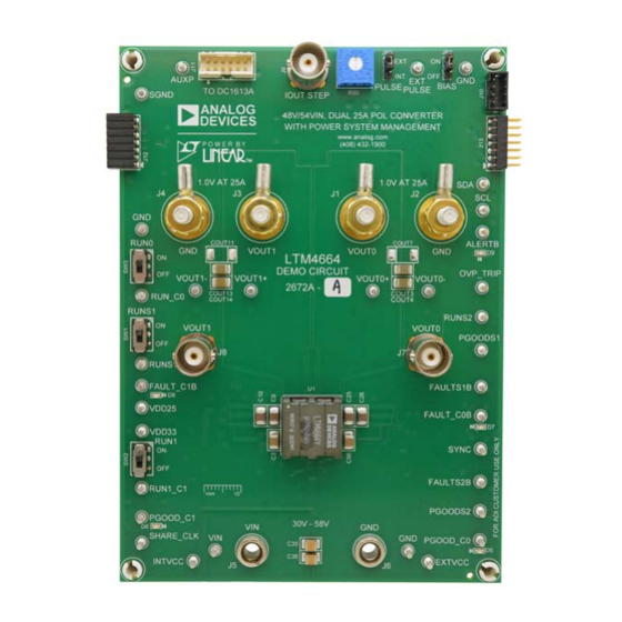
BOARD PHOTO
48V
, Dual 25A µModule Regulator
IN
With Digital Power System Management
Figure 1. Dual-output LTM4664/DC2672A-A Demo Circuit
DEMO MANUAL DC2672A-A
the GUI software LTpowerPlay™ onto your PC and use
2
ADI's I
C/SMBus/PMBus dongle DC1613A to connect to
the board. LTpowerPlay allows the user to reconfigure the
part on the fly and store the configuration in EEPROM, view
telemetry of voltage, current, temperature and fault status.
GUI Download
The software can be downloaded here.
For more details and instructions of LTpowerPlay, please
refer to LTpowerPlay GUI for LTM4664 Quick Start Guide.
Design files for this circuit board are
All registered trademarks and trademarks are the property of their respective owners.
LTM4664
available.
Rev. 0
1
Advertisement

Related Manuals for Analog Devices LINEAR DC2672A-A


Summary of Contents for Analog Devices LINEAR DC2672A-A
- Page 1 DEMO MANUAL DC2672A-A LTM4664 , Dual 25A µModule Regulator With Digital Power System Management DESCRIPTION Demonstration circuit 2672A-A is a complete non-iso- the GUI software LTpowerPlay™ onto your PC and use lated 48V input, dual-output, high efficiency, high density ADI’s I C/SMBus/PMBus dongle DC1613A to connect to µModule regulator with 30V to 58V input range.
-
Page 2: Performance Summary
DEMO MANUAL DC2672A-A PERFORMANCE SUMMARY Specifications are at T = 25°C PARAMETER CONDITIONS VALUE Input Voltage Range 30V to 58V Output Voltage, V = 30-58V, I = 0A to 25A 0.5 to 1.5V, Default: 1.0V OUT0 OUT0 Maximum Output Current, I = 30-58V, V = 0.5V to 1.5V OUT0... - Page 3 DEMO MANUAL DC2672A-A QUICK START PROCEDURE Figure 2. Proper Measurement Equipment Setup Rev. 0...
- Page 4 DEMO MANUAL DC2672A-A QUICK START PROCEDURE Figure 3. Measuring Output Voltage Ripple Connecting a PC to DC2672A-A margin set points, OV/UV limits, temperature fault limits, sequencing parameters, the fault log, fault responses, You can use a PC to reconfigure the power manage- GPIOs and other functionalities.
- Page 5 DEMO MANUAL DC2672A-A QUICK START PROCEDURE (20MHz BW) (20MHz BW) OUT1 OUT0 20mV/DIV 20mV/DIV 0A-6.25A 0A-6.25A LOAD STEP LOAD STEP 100 s/DIV 100 s/DIV Figure 7. V Load Transient Response Figure 8. V Load Transient Response OUT0 OUT1 at V = 48V, V = 1.0V at V = 48V, V...
- Page 6 The software supports a variety of different tasks. You board. The software also provides an automatic update can use LTpowerPlay to evaluate Analog Devices ICs by feature to keep the software current with the latest set connecting to a demo board system. LTpowerPlay can of device drivers and documentation.
- Page 7 DEMO MANUAL DC2672A-A QUICK START PROCEDURE QUICK START PROCEDURE LTpowerPlay Quick Start Procedure d. If you want to change the output voltage to a differ- ent value, like 1.5V. In the Config tab, type in 1.5 in the The following procedure describes how to use LTpow- VOUT_COMMAND box, like this: erPlay to monitor and change the settings of LTM4664.
- Page 8 PANASONIC, ERJ3EKF4991V RES, 0603 130k OHMS 1% 0.1W VISHAY, CRCW0603130KFKEA RES. 0603 9.76k OHMS, 1%, 1/10W VISHAY, CRCW06039K76FKEA IC, Module ANALOG DEVICES, LTM4664EY Additional Demo Board Circuit Components COUT7, COUT8, COUT11, CAP , 7343 OPTION OPTION COUT16 CAP , 0603 OPTION...
-
Page 9: Parts List
R72, R74, R85, R114 RES, 0603 10K OHMS 5% 1/10W VISHAY, CRCW060310K0JNEA RES, 0603 34.8K OHM 1% 1/10W VISHAY, CRCW060334K8FKEA IC, REGULATOR ANALOG DEVICES, LT1761ES5-SD RES, 0603 154K OHMS 1% 1/10W VISHAY, CRCW0603154KFKEA R80, R83 RES, 0603 20K OHMS 5% 1/10W VISHAY, CRCW060320K0JNEA... - Page 10 DEMO MANUAL DC2672A-A PARTS LIST ITEM REFERENCE PART DESCRIPTION MANUFACTURER/PART, NUMBER D7, D8, D9 LED, 0603 RED WURTH ELEKTRONIK, 150060SS75000 Q3, Q4, Q6, Q7 XSTR, P-CHANNEL DMOS FET DIODES INC., DMP3130L-7 Q5, Q8 XSTR, N-CHANNEL DMOS FET DIODES, INC., 2N7002A-7 R101, R102 RES, 0603 10 OHMS 5% 1/10W VISHAY, CRCW060310R0JNEA...
-
Page 11: Schematic Diagram
DEMO MANUAL DC2672A-A SCHEMATIC DIAGRAM Rev. 0... - Page 12 DEMO MANUAL DC2672A-A SCHEMATIC DIAGRAM Rev. 0...
- Page 13 Devices for its use, nor for any infringements of patents or other rights of third parties that may result from its use. Specifications subject to change without notice. No license is granted by implication or otherwise under any patent or patent rights of Analog Devices.
- Page 14 Board until you have read and agreed to the Agreement. Your use of the Evaluation Board shall signify your acceptance of the Agreement. This Agreement is made by and between you (“Customer”) and Analog Devices, Inc. (“ADI”), with its principal place of business at One Technology Way, Norwood, MA 02062, USA. Subject to the terms and conditions of the Agreement, ADI hereby grants to Customer a free, limited, personal, temporary, non-exclusive, non-sublicensable, non-transferable license to use the Evaluation Board FOR EVALUATION PURPOSES ONLY.
Need help?
Do you have a question about the LINEAR DC2672A-A and is the answer not in the manual?
Questions and answers