Page 1
SAFETY & OPERATING INSTRUCTIONS Models: - Premier Pro SP Pro-SP Model Shown DR Power Equipment Serial No. Toll-free phone: 1-800-DR-OWNER (376-9637) Order No. Website: www.DRpower.com Read and understand this manual and all instructions before operating the DR WALK-BEHIND LAWN VACUUM.
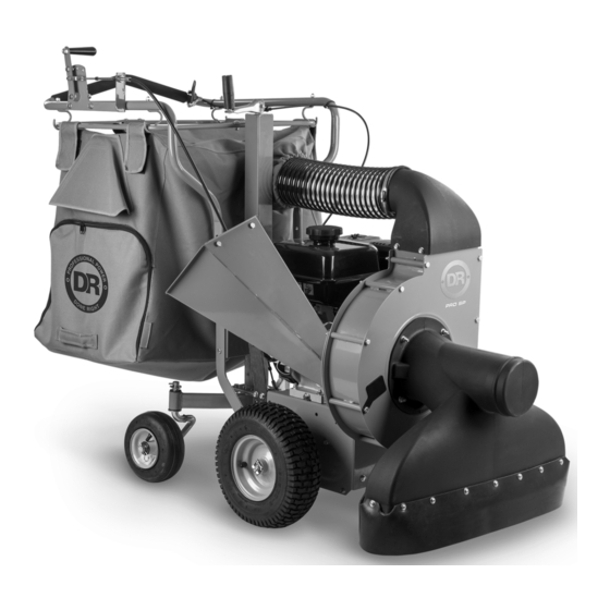
Additional Information and Potential Changes DR Power Equipment reserves the right to discontinue, change, and improve its products at any time without notice or obligation to the purchaser. The Figure 1 descriptions and specifications contained in this manual were in effect at printing.
Safety and Information labels that appear on the equipment. Take a moment to study them and make a note of their location on your DR WALK-BEHIND LAWN VACUUM as you set up and before you operate the unit. Replace damaged or missing safety and information labels immediately.
Page 4
This label indicates proximity to machine openings with rotating blades Always wear protective goggles or inside. safety glasses with side shields while chipping to protect your eyes from SERIOUS INJURY OR DEATH will occur possible thrown debris. if hands, feet, or any part of your body are placed in the chipper hopper, Use ear protectors or ear plugs rated discharge opening, or near or under any...
Page 5
Avoid wearing loose clothing or jewelry, which can catch on the machine’s moving parts. We recommend wearing gloves while using your DR Walk-Behind Lawn Vacuum. Be sure your gloves fit properly and do not have loose cuffs or drawstrings.
Page 6
Allow the engine to cool completely and empty the debris bag before storing the DR Walk-Behind Lawn Vacuum in any enclosure. Remember, decomposing material generates heat and could start a fire. Never store the machine with gas in the tank or a fuel container, near an open flame or spark such as a water heater.
Page 7
Keep in mind that the operator or user is responsible for accidents or hazards occurring to other people, their property, and themselves. Your DR walk-behind lawn vacuum is a powerful tool, not a plaything. Exercise extreme caution at all times. The design of this machine is to vacuum debris. Do not use it for any other purpose. ...
WALK-BEHIND LAWN VACUUM It may be helpful to familiarize yourself with the controls and features of your DR WALK-BEHIND LAWN VACUUM as shown in Figures 2a and 2b before beginning these procedures. If you have any questions at all, please feel free to contact us at www.DRpower.com.
Page 9
DR WALK-BEHIND LAWN VACUUM PREMIER Controls and Features Handlebar with Height Adjuster Foam Grip Handle Air Vent Fuel Tank Cap Discharge Access Chute Door Vacuum Housing Snout Lid Collection Bag Rear Pneumatic Steering Wheels Vacuum Snout Figure 2b CONTACT US AT www.DRpower.com...
Page 10
Specifications Premier WB Leaf Vac Pro WB Leaf Vac M/S Pro WB Leaf Vac E/S Engine See Engine Owner’s Manual See Engine Owner’s Manual See Engine Owner’s Manual Engine Oil Capacity 0.5 Liters (16.9 oz) 1.1 Liters (37.2 oz) Engine Oil Type...
Page 11
Assembling the DR WALK-BEHIND LAWN VACUUM Outlet Hose Chipper Hopper Note: Assembly should be done on a clean, level surface. Tools Needed: Two 1/2" Wrenches The pictures reference the Pro model; however, the assembly is the same for both models.
Page 12
7. Swing the Bag Frame upward while pulling toward the Right-Side Bag Left Side Bag Hangers Hangers. The Bag Frame will ramp up on the Left Side Bag Hangers allowing you to secure the Frame to the Right-Side Bag Hangers (Figure 8). 8.
Page 13
Pro: 1.1 Liters (37.2 oz) Fuel Unleaded gasoline To add Engine Oil on Premier Models: 1. Level the Lawn Vacuum by rotating the Height Adjust Handle (Figure 12). 2. Remove the Oil Fill/Dipstick and add an initial quantity of the Oil Figure 13 recommended by the Engine Manufacturer (refer to your Engine Owner’s...
Page 14
To add Engine Oil on Pro Models: Your PRO DR WALK-BEHIND LAWN VACUUM Engine comes from the factory with two fill points. The left side has an Oil fill Cap (Figure 15), and the right side Oil Fill Cap has an Oil Fill/Dipstick (Figure 16). Because of the Chipper Hopper the location of the Dipstick is inaccessible.
Chapter 3: Operating the DR WALK-BEHIND LAWN VACUUM It may be helpful to better familiarize yourself with the features of your DR Throttle Lever WALK-BEHIND LAWN VACUUM by reviewing Figure 2a for Pro Models and Figure 2b For Premier Models in Chapter 2 before beginning the steps outlined in this chapter.
Page 16
Operating the Drive System (PRO Model) Transmission Engagement Lever There are two controls, the Range Select Lever, and the Transmission Engage Lever, that are used to engage and disengage the drive wheels (Figure 21). Familiarize yourself with these controls before you start the Engine. ...
Page 17
Before leaves drop, mow your lawn to the shortest recommended height. Your DR WALK-BEHIND LAWN VACUUM will perform better on short grass. The DR WALK-BEHIND LAWN VACUUM is designed to be used frequently during periods when leaves are dropping. It is not recommended to let leaves get 4”, or deeper. ...
Page 18
Height adjust Adjusting the Vacuum Snout Height Lower Handle The height of the Vacuum Snout can be adjusted to allow you to vary the suction to meet the surface conditions. For short turf with light leaf fall, the Snout should be lowered closer to the surface.
Page 19
Emptying the Collection Bag Collection Never start the Engine without the Collection Bag attached firmly to the Discharge Chute and Outlet Hose. Access Door Empty the Bag as soon as it is full (check by feeling sides of Bag). Overfilling the bag will cause the vacuuming performance to decrease or stop completely and could lead to clogging of the discharge tube, snout, or both.
Page 20
5. Carry the Collection Bag to the dumping area, unzip the Access Door and remove the Material. 6. Zip the Access Door closed. 7. Reattach the Collection Bag (Figure 28). 8. Reinstall the Cuff, pulling the Cuff fully Forward onto the Hose (Figure 27). Left Bag Right Bag Hanger...
Chapter 4: Maintaining the DR WALK-BEHIND LAWN VACUUM Regular maintenance is the way to ensure the best performance and long life of your machine. Please refer to this manual and the Engine Manufacture’s Owner’s Manual for maintenance procedures. Service intervals listed in the checklist below supersede those listed in the Engine Manufacture’s Owner’s Manual.
Page 22
1. Position an Approved Oil Container under the machine below the Engine Oil Figure 32 Drain Plug. The Premier Drain plug is on the right-hand side of the Engine (Figure 32), and the Pro Is on the Left-hand side (Figure 33) 2.
Page 23
Replacing the Chipper Knife The PRO DR WALK-BEHIND VACUUM is shipped with a sharp Chipper Knife Belt and depending upon material being chipped we've found it can remain Cover acceptably sharp for 40 plus hours. When you notice diminished feeding, it is time to replace the knife.
Page 24
Inside Allen 6. Remove the inside Allen Screw from the Knife and carefully allow the Knife to Knife Edge Screw Removed swing down. 7. Align the Knife edge with the long edge of the Window, then carefully remove the Knife and Screw together (Figure 40). 8.
Page 25
Sharpening the Chipper Knife Discard a cracked or severely nicked Knife because it could break apart and damage the machine and cause personal injury. Over a period of time, the cutting edge on the Chipper Cutting Knife will dull. The Cutting Knife must be sharpened or replaced in order to restore performance.
Page 26
Replacing the Drive Belt Tools and Supplies needed: Belt Guard 10mm Wrench 3/8" Wrench 13mm Wrench 1/2" Wrench Pliers Diagonal Cutting Pliers 1. Locate a clean flat surface to work on. Bolt Frame 2. Use the Height Adjust Handle to raise the Snout so that the machine is tipped back.
Page 27
7. Lift the Drive Assembly upward in the Frame as you remove the Linked Belt from the Drive Pulley (Figure 47). Note: There is a spacer on the Hopper side of the Pivot shaft, this will slide off as Spacer you raise the drive unit (Figure 48).
Page 28
11. Assemble the Belt Link and Tabs: 1st End 1st End Twist the Belt to Line up the 1st End Tab with the End Tab Slot in the Doubled Link section. Insert the Tab through the Slot (Figure Slot 50). b.
Page 29
Operate the Engine for at least 45 minutes to maintain proper Battery charge. If the Battery loses its charge, you'll need to use a trickle Charger (like the DR Battery Charger) to recharge it. The Charger should have an output of 12 volts at no more than 2 amps.
Most problems are easy to fix. Consult the Troubleshooting Table below for common problems and their solutions. If you continue to experience problems, contact us at www.DRpower.com or call toll-free 1-800-DR-OWNER (376-9637) for support. Before performing any maintenance procedure or inspection, stop the Engine and wait five minutes to allow all parts to cool.
Page 31
Stretched or broken Drive Belt; Replace Belt. Drive Engagement Cable tension spring broken; Reconnect spring or replace cable. Malfunction in Range Select Assembly; contact us at www.DRpower.com or call 1-800-DR- OWNER (376-9637) for assistance. Loose Range Select Lever; Check connections for loose Nuts and Bolts.
Chapter 6: Parts Lists and Schematic Diagrams Parts List – Premier Handlebar and Bagger Assembly Note: Part numbers listed are available through DR Power Equipment. Ref# Part# Description Ref# Part# Description 10000038366 Side, Common 333311 Nut, Nylon Lock, Flanged, 1/4-20...
Page 33
Schematic – Premier Handlebar and Bagger Assembly CONTACT US AT www.DRpower.com...
Page 34
Parts List – Premier Vacuum Assembly Note: Part numbers listed are available through DR Power Equipment. Ref# Part# Description Ref# Part# Description 354331 Engine, DR 9.59TQ, MS 50st 311611 Bolt, Taptite, 5/16-18 X .75" W/Labels 134431 Bolt, HCS, 5/16-18 X 1-1/2", GR5 ZP...
Page 35
Schematic – Premier Vacuum Assembly CONTACT US AT www.DRpower.com...
Page 36
Parts List – Pro Handlebar and Bagger Assembly Note: Part numbers listed are available through DR Power Equipment. Ref# Part# Description Ref# Part# Description 10000038358 Frame, Bag, Half 160031 Pin, Hair, 1/2" To 9/16", .12" Wire 10000038475 Bag, Pro 333311...
Page 37
Schematic – Pro Handlebar and Bagger Assembly CONTACT US AT www.DRpower.com...
Page 38
Parts List – Pro Vacuum Assembly Note: Part numbers listed are available through DR Power Equipment. Ref# Part# Description Ref# Part# Description 10000038388 Chute 10000038599 Guard, Chipper 354361 Engine, DR 13.28 TQ, E/S, 50st/Ce 10000039382 Back, Impeller W/Labels A0000296223 Front, Impeller, w/Labels...
Page 39
Schematic – Pro Vacuum Assembly CONTACT US AT www.DRpower.com...
Page 40
Parts List – Pro Drive Assembly Note: Part numbers listed are available through DR Power Equipment. Ref# Part# Description Ref# Part# Description 286971 Pad, Battery 2.5 X 6.125 401821 Pulley, Belt 258621 Bracket, Battery, 9 Ah 401831 Seat, Bearing Delta...
Page 41
Schematic – Pro Drive Assembly CONTACT US AT www.DRpower.com...
Page 44
If your DR WALK-BEHIND LAWN VACUUM will be idle for more than 30 days, we recommend using a gas stabilizer. This will prevent sediment from gumming up the Carburetor. If there is dirt or moisture in the gas or tank, remove it by draining the tank.
Need help?
Do you have a question about the Premier and is the answer not in the manual?
Questions and answers