DR Premier Safety & Operating Instructions Manual
Leaf & lawn vacuum
Hide thumbs
Also See for Premier:
- Safety & operating instructions manual (52 pages) ,
- Safety and operating instructions manual (44 pages) ,
- Safety & operating instructions manual (32 pages)
Table of Contents
Advertisement
®
DR
LEAF & LAWN VACUUM
SAFETY & OPERATING INSTRUCTIONS
Models:
- Premier
- Pro
- Pro-XL
Serial No.
Order No.
Read and understand this manual and all instructions before operating the DR LEAF and LAWN VACUUM.
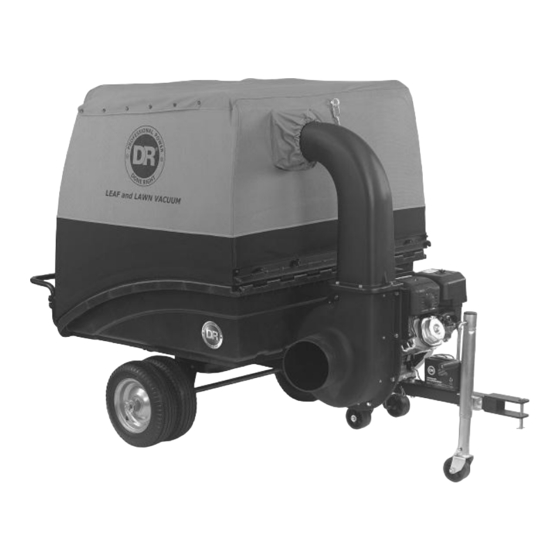
Pro-XL Model Shown
Original Language
DR Power Equipment
Toll-free phone: 1-800-DR-OWNER (376-9637)
Fax: 1-802-877-1213
Website: www.DRpower.com
CONTACT US AT www.DRpower.com
1
Advertisement
Table of Contents

Related Manuals for DR Premier


Summary of Contents for DR Premier
- Page 1 Pro-XL Model Shown DR Power Equipment Toll-free phone: 1-800-DR-OWNER (376-9637) Serial No. Fax: 1-802-877-1213 Original Language Order No. Website: www.DRpower.com CONTACT US AT www.DRpower.com Read and understand this manual and all instructions before operating the DR LEAF and LAWN VACUUM.
-
Page 2: Table Of Contents
Additional Information and Potential Changes DR Power Equipment reserves the right to discontinue, change, and improve its products at any time without notice or obligation to the purchaser. The descriptions and specifications contained in this manual were in effect at printing. Equipment described within this manual may be optional. -
Page 3: Chapter 1: General Safety Rules
Labels Your DR LEAF and LAWN VACUUM carries prominent labels as reminders for its proper and safe use. Shown below are copies of all the Safety and Information labels that appear on the equipment. Take a moment to study them and make a note of their location on your machine as you set up and before you operate the unit. - Page 4 Keep children and pets at least 100 feet from the working area and ensure they are under the watchful care of a responsible adult. Be alert and always turn off the lawn tractor engine and the DR Leaf and Lawn Vacuum engine if children or pets enter the work area. ...
-
Page 5: Slope Operation
Allow the engine to cool completely and empty the collector box before storing the DR Leaf and Lawn Vacuum in any enclosure. Remember, decomposing material can generate heat and start a fire. Never store the machine with gas in the tank or a fuel container, near an open flame or spark such as a water heater, space heater, clothes dryer or furnace. - Page 6 Check behind your DR Leaf and Lawn Vacuum before backing up. You cannot see directly behind the collector box. Never attempt to open or empty the collector while the lawn tractor deck is engaged or the DR Leaf and Lawn Vacuum engine is running. Debris may exit at high velocity as you begin to open the collector.
-
Page 7: Chapter 2: Setting Up The Dr Leaf And Lawn Vacuum
Chapter 2: Setting Up the DR LEAF and LAWN VACUUM It may be helpful to familiarize yourself with the controls and features of your DR LEAF and LAWN VACUUM as shown in Figure 1 If you have any questions at all, please feel free to contact us at www.DRpower.com. -
Page 8: Specifications
Specifications PREMIER PRO-XL Engine DR Power Equipment R225 DR Power Equipment R300 DR Power Equipment R390 Ft-lbs Torque 9.59 13.28 16.96 Starting Manual or Electric w/ Recoil Backup Manual or Electric w/ Recoil Backup Manual or Electric w/ Recoil Backup... - Page 9 9 ..... Hinge, Tube Frame ..........1 10 ... Enclosure, Fabric ............. 1 Small Parts Box 11 ... Tube Frame, Collector, Top ........1 Figure 4 *Only one Gas Spring used for Premier Small Box Parts (Figure 5): Item # Part # Description 1 .....
- Page 10 Power Unit Hardware (Figure 6):* Item # Part # Description 1 ..... 35023 ....Bolt, Hex, Flange, 5/16-18 X .75" ....6 2 ..... 26556 ....Bolt, HCS, 1/2-13 X 2.75", GR5, ZP....2 3 ..... 33335 ....Nut, Nylon Lock, Flange, 1/2-13 ....2 4 .....
- Page 11 Installing the Gas Spring/s Washer Note: The Premier uses one Gas Spring. The Pro and ProXL use two Gas Springs. 1. Tilt the Cart Bed up by pulling the Lift Handle out and lifting up on the front Figure 11 of the Cart (Figure 12).
- Page 12 5. Lift the Cart Frame to align the rear hole in the Engine Unit with the hole in the Frame and insert a 1/2" X 3.5" Clevis Pin and Hitch Clip (Clevis Pins and Hitch Clips are provided in the Product Package) (Figure 16). 6.
- Page 13 Hose Bridge 11. Using a Flat Head Screwdrive or 5/16" Wrench, loosen the Hose Bridge Clamp Clamp, slide the hose onto the Housing neck, and tighten the Hose Bridge Clamp very tightly (Figure 21). Note: Make sure the Hose Bridge Clamp is past the Retaining Bumps on the Housing.
- Page 14 3. Insert the Retainer into the rear opening in the Fabric with the Studs tilted Angled Stitching slightly so they do not catch in the fabric holes (Figure 25). Rear 4. Slide the Retainer all the way in and then twist to align the Studs into the Fabric Holes (Figure 26).
- Page 15 10. Lift up on the sides of the Enclosure so the Tube Frames go down inside the Enclosure Fabric (Figure 31). Front Rear 11. Inside the Collector, insert a 5/16-18 X 1.75" C-Head Bolt up through the Side Frame Tube on both sides and place a Flat Washer into the Bolt threads (Figure 32).
- Page 16 Rack Note: The Enclosure Fabric is intentionally a tight fit. It may be easier if you have a helper for the next few steps. 19. Position the Tube Frame Handle onto the two upper corner Bolts at the rear and loosely secure with Knobs (Figure 38). 20.
- Page 17 Tube Frame 27. Wrap the Enclosure Flap tightly around the Tube Frame Handle at the rear Handle and secure the Velcro Strips (Figure 43). 28. Insert the Eyebolt through hole in the Enclosure at the front and into the hole in the Top Tube Frame (Figure 44).
- Page 18 1. Install the Deck Adapter onto your Lawn Tractor (Figure 49). 2. If you do not have a DR Deck Adapter and the 8" Hose will not fit your Adapter, order a Kit from us using the contact info above. Install the Hose Adapter Kit onto the end of your Deck Adapter as described in the Kit instructions.
- Page 19 Deck Connecting the Inlet Hose to the Deck Adapter Adapter Tools Needed: Thumb Screw Clamp Wire Cutters Knife 5/16" Wrench Hose Cuff 1. Connect the Inlet Hose to the Deck Adapter by sliding the Hose Cuff over the Hose Adapter (Figure 51).
- Page 20 Wire Cutter Cut Point d. Cut the Hose to the length required using Wire Cutters to cut the black Knife Cut Line (black Rib) plastic spiral and then cut the clear Hose with the razor knife (Figure (clear plastic) 55). NOTE: Make sure you trace the area to cut around the Hose first to ensure you will cut in the proper direction to end up on either side of the cut spiral.
- Page 21 We ship all Electric-Starting systems with the Negative Battery Terminal Wire disconnected. This prevents the Battery from discharging during shipment. Before using your DR LEAF and LAWN VACUUM, you must connect the Battery Wire. 1. Connect the Negative Wire to the Negative Post on the Battery by sliding the Terminal onto the Battery Post (Figure 58).
-
Page 22: Chapter 3: Operating The Dr Leaf And Lawn Vacuum
Chapter 3: Operating The DR LEAF AND LAWN VACUUM It may be helpful to better familiarize yourself with the features of your DR LEAF and LAWN VACUUM by reviewing Figure 1 in Chapter 2 before beginning the steps outlined in this chapter. -
Page 23: Operating Safety
Rubber Washer 1. Make sure you firmly attach the DR LEAF and LAWN VACUUM Hitch to your Lawn Tractor using the Hitch Pin and Hitch Clip (Figure 60). 2. If equipped with a Jack, make sure the wheel is in the fully raised position and the Jack Safety Pin is installed to lock it in place. - Page 24 Be careful in corners. Practice in first gear to understand the effects of the machine on your ability to turn sharply. Drive your DR LEAF and LAWN VACUUM into the corner of your property and back out straight to mow as close to the corner as possible.
- Page 25 Cut wet grass can be very heavy. Fill the Collector only 3/4 full if the Lock Collector material is very wet. That will make the Leaf System easier to pull and to dump. Dumping Unlock Collector Always shut off the tractor engine and the vacuum engine and use caution when dumping the collector load.
- Page 26 Converting to Cart Trailer Mode Hose Support Before performing any maintenance, repairs or inspection, you must first shut off the mower and leaf and lawn vacuum engines, wait five minutes for all parts to stop and cool, and disconnect the spark plug wire of the leaf and lawn vacuum.
- Page 27 Note: The Gas Spring makes it easier to dump the loads in the Collector. The Premier unit has one Gas Spring and can be left as is for Cart Mode. The Pro and Pro XL use two Gas Springs and the left hand Spring should be removed so closing the Cart is easier in Cart mode.
- Page 28 19. Hitch the Tow Bar of the Cart to your Tractor using the Hitch Pin with Rubber Rubber Washer and secure using the Hitch Clip (Figure 79). Washer Never allow anyone to ride in the Cart. Do not tow on slopes greater than 15 degrees. Tow Bar ...
- Page 29 4. Slide the Retainer on the Link and scissor the Links partially closed (Figure 84). Retainer 5. Prop the Upper Collector upright then standing to the side pull the front and back Enclosure fabric (Figure 85). 6. Fully collapse by pulling the sides together. Lift and store. Also store the Hinge, Handle, and Top Tube Frame with the Enclosure.
-
Page 30: Chapter 4: Maintaining The Dr Leaf And Lawn Vacuum
Lubrication Your DR LEAF and LAWN VACUUM was lubricated at the Factory. The operator needs to provide Engine lubrication and lubricate the Wheels periodically. Before performing any maintenance, repairs or inspection, you must first shut off the mower and leaf and lawn vacuum engines, wait five minutes for all parts to stop and cool, and disconnect the spark plug wire of the leaf and lawn vacuum. - Page 31 REMOVING AND REPLACING THE ENGINE OIL Refer to the Engine Operator Manual for Engine Procedures for removing and replacing the oil. NOTE: Be sure to use environmentally safe disposal procedures in the disposing of the used oil. Replacing the Wheels Before performing any maintenance, repairs or inspection, you must first shut off the mower and leaf and lawn vacuum engines, wait five minutes for all parts to stop and cool, and disconnect the spark plug wire of the leaf and lawn vacuum.
-
Page 32: Charging The Battery
Operate the vacuum Engine for at least 45 minutes to maintain proper Battery charge. If the Battery loses its charge, you will need to use a trickle charger (like the DR Battery Charger) to recharge it. The Charger should have an output of 12 volts at no more than 2 amps. - Page 33 Replacing the Battery Tools Needed: Two 7/16" Wrenches Wire Cutters 1. Disconnect the Battery Terminals (Figure 89). Terminals 2. Cut the Cable Tie that securing the Wires to the Clamp using Wire Cutters. 3. Remove the Bolts and Locknuts that secure the Battery Clamp using two 7/16"...
-
Page 34: Chapter 5: Troubleshooting
Battery may need to be periodically charged. See the Battery Care section in Chapter 4. If your Battery is charged and your DR still won’t start, visit us at www.DRpower.com or call 1- 800-DR-OWNER (376-9637) for assistance. - Page 35 If your Engine still lacks power, visit us at www.DRpower.com or call 1-800-DR-OWNER (376- 9637) for assistance. Check the tire pressure. Refer to the Tire manufacturers recommended pressure on the side of Wheels tracking left or right while being towed.
-
Page 36: Chapter 6: Parts Lists, Schematic Diagrams And Warranty
Chapter 6: Parts Lists and Schematic Diagrams Parts List – FRAME AND CART ASSEMBLY NOTE: Part numbers listed are available through DR Power Equipment. Ref# Part# Description Ref# Part# Description 33799 Frame, Rear 33798 Stud, Ball, 10 mm 18737 Pin, Clevis, 1/2" OD X 4.5" LG 35443 Handle W/Grip &... - Page 37 Schematic – FRAME AND CART ASSEMBLY CONTACT US AT www.DRpower.com...
- Page 38 Parts List – POWER UNIT ASSEMBLY NOTE: Part numbers listed are available through DR Power Equipment. Ref# Part# Description Ref# Part# Description 33800 Frame, Front 11250 Washer, Lock, 5/16", Ext Tooth (PREMIER E/S) 33799 Frame, Rear 35040 Washer, Lock, 3/8", Ext Tooth (PRO &...
- Page 39 Schematic – POWER UNIT ASSEMBLY CONTACT US AT www.DRpower.com...
-
Page 40: Eyebolt, 5/16-18 X 2", Forged, Zp 1
Parts List – COLLECTOR ASSEMBLY NOTE: Part numbers listed are available through DR Power Equipment. Ref# Part# Description Ref# Part# Description 33792 Enclosure, Fabric, PREMIER 35028 Eyebolt, 5/16-18 X 2", Forged, ZP 34268 Enclosure, Fabric, PRO & XL 33443 Link, Chain, Threaded Connector... - Page 41 Schematic – COLLECTOR ASSEMBLY CONTACT US AT www.DRpower.com...
-
Page 42: Strap And Hook Set
Parts List and Schematic – HOSE ASSEMBLY NOTE: Part numbers listed are available through DR Power Equipment. Ref# Part# Description 35441 Housing W/ Label, Impeller 33795 Hose, 8" ID X 72" Long, PVC 34248 Cuff, Hose, 8" 33796 Clamp, Hose, 8", Bridge 33797 Clamp, Hose, 8", Thumbscrew... -
Page 43: Contact Us At Www.drpower.com
Notes: CONTACT US AT www.DRpower.com... - Page 44 If your DR LEAF and LAWN VACUUM will be idle for more than 30 days, we recommend using a gas stabilizer. This will prevent sediment from gumming up the carburetor. If there is dirt or moisture in the gas or tank, remove it by draining the tank.
Need help?
Do you have a question about the Premier and is the answer not in the manual?
Questions and answers