DR Premier Safety & Operating Instructions Manual
Leaf & lawn vacuum
Hide thumbs
Also See for Premier:
- Safety & operating instructions manual (44 pages) ,
- Safety and operating instructions manual (44 pages) ,
- Safety & operating instructions manual (33 pages)
Advertisement
DR
®
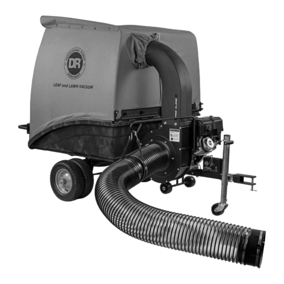
LEAF & LAWN VACUUM
SAFETY & OPERATING INSTRUCTIONS
Models:
Premier
Pro
Pro-XL
Serial No.
Order No.
Read and understand this manual and all instructions before operating the DR LEAF and LAWN VACUUM.
DR Power Equipment
Toll-free phone: 1-800-DR-OWNER (376-9637)
Website: www.DRpower.com
CONTACT US AT www.DRpower.com
1
Advertisement

Subscribe to Our Youtube Channel
Related Manuals for DR Premier


Summary of Contents for DR Premier
- Page 1 SAFETY & OPERATING INSTRUCTIONS Models: Premier Pro-XL DR Power Equipment Serial No. Toll-free phone: 1-800-DR-OWNER (376-9637) Order No. Website: www.DRpower.com Read and understand this manual and all instructions before operating the DR LEAF and LAWN VACUUM. CONTACT US AT www.DRpower.com...
-
Page 2: Table Of Contents
Table of Contents Chapter 1: General Safety Rules ................................3 Chapter 2: Setting Up the DR LEAF and LAWN VACUUM ........................8 Chapter 3: Operating the DR LEAF AND LAWN VACUUM ......................... 30 Chapter 4: Maintaining the DR LEAF and LAWN VACUUM ....................... 38 Chapter 5: Troubleshooting .................................. -
Page 3: Chapter 1: General Safety Rules
Labels Your DR LEAF and LAWN VACUUM carries prominent labels as reminders for its proper and safe use. Shown below are copies of all the Safety and Information labels that appear on the equipment. Take a moment to study them and make a note of their location on your machine as you set up and before you operate the unit. - Page 4 Keep children and pets at least 100 feet from the working area and ensure they are under the watchful care of a responsible adult. • Be alert and always turn off the lawn tractor engine and the DR Leaf and Lawn Vacuum engine if children or pets enter the work area. •...
- Page 5 • Allow the engine to cool completely and empty the collector box before storing the DR Leaf and Lawn Vacuum in any enclosure. Remember, decomposing material can generate heat and start a fire. Never store the machine with gas in the tank or a fuel container, near an open flame or spark such as a water heater, space heater, clothes dryer or furnace.
- Page 6 Check behind your DR Leaf and Lawn Vacuum before backing up. You cannot see directly behind the collector box. • Never attempt to open or empty the collector while the lawn tractor deck is engaged or the DR Leaf and Lawn Vacuum engine is running. Debris may exit at high velocity as you begin to open the collector.
- Page 7 The DR Leaf and Lawn Vacuum must be operated safely to prevent or minimize the risk of minor or moderate injury. Unsafe operation can create a number of hazards for you. Always take the following precautions when operating this machine: •...
-
Page 8: Chapter 2: Setting Up The Dr Leaf And Lawn Vacuum
Chapter 2: Setting Up the DR LEAF and LAWN VACUUM It may be helpful to familiarize yourself with the controls and features of your DR LEAF and LAWN VACUUM as shown in Figure 1 If you have any questions at all, please feel free to contact us at www.DRpower.com. - Page 9 Specifications PREMIER PRO-XL Engine DR Power Equipment R225 DR Power Equipment R300 DR Power Equipment R390 Ft-lbs Torque 9.59 13.28 16.96 Starting Manual or Electric w/ Recoil Backup Manual or Electric w/ Recoil Backup Manual or Electric w/ Recoil Backup...
- Page 10 Compare the contents of the Parts Boxes and Hardware Packages with the Parts Supplied lists and Figures 3 thru 8 below. If there are any questions contact us at www.DRpower.com or call 1-800-DR-OWNER (376-9637). There may be hardware left over when assembly is finished. This is sometimes expected in the process of filling hardware bags at the factory.
- Page 11 Small Box Parts (Figure 5): Item # Part # Description 1 ..... A0001844373 ..Bracket, Stop ..........2 2 ..... 354421 ....Strap and Hook Set ........1 3 ..... 338021 ....Bracket, Axle ..........2 4 ..... 350211 ....Hardware Set, Wheels ........ 1 5 .....
- Page 12 2 ..... 123341 ....Bolt, HCS, 3/8-16 X 1.75", GR5, ZP ..... 4 3 ..... 333331 ....Nut, Nylon Lock, Flange, 3/8-16 ....4 4 ..... 126851 ....Pin, Cotter, 3/16" X 1.5" ....... 2 **Only two needed for Premier (single wheel) machines. Figure 8 Installing the Wheels...
- Page 13 Figure 11 installed (Figure 4, item 8) *(PRO MODELS ONLY). Leave the Cart in the up position for the following procedure. (PREMIER models skip to step 7) 4. Remove the two 5/16-18 nuts using a 1/2" wrench while keeping a finger on the head of the carriage bolt inside the bed so it does not rotate.
- Page 14 Outlet Chute Assembling the Power Unit (Use Power Unit Hardware Package, see Figure 6) Tools Needed: • 1/2" Wrench or 1/2" Ratcheting Socket • Bolts, Lock Washers, 3/4" Wrench and 3/4" Ratcheting Socket and Flat Washers • Scissors / diagonal cutters •...
- Page 15 Assembling the Collector RH Tube Frame (Use Enclosure Hardware Set, see Figure 7 and Product Package Hardware, see Figure 3) Note: The Enclosure Fabric is intentionally a tight fit. Assembly is LH Tube much easier when you perform the following procedures in order. Frame Tools Needed: •...
- Page 16 Side Flaps Folded In Installing the Side Retainers 1. Lay out the Enclosure onto a clean flat surface so the inside (black) is Front Sleeve facing up (Figure 27). Take note of the Sleeve location at the front of the Enclosure. Inner Enclosure (Black) 2.
- Page 17 Attaching the Enclosure, Retainer Studs (Use Hardware Enclosure set, see Figure 7) It is best to do this install up against a wall, to keep the enclosure upright while working. 1. Lift one side of the Enclosure so the studs on the Side Retainer go into the Tube Frame Assembly slots (Figure 30).
- Page 18 Installing the Front Retainers 1. Insert one of the Front Retainers into the Front Corner canvas pocket. Slide the Front Retainers in at an angle to avoid the studs catching on the canvas as they are inserted (Figure 34). 2. Align the studs through the holes in the canvas (Figure 35). 3.
- Page 19 Setting the Initial Canvas Width Flat Link 1. Step into the open canvas and push the sides out with both feet to aid in setting the canvas width. 2. Set the Inner Scissor Link assembly width by pushing down on the flat link until both parts come to parallel.
- Page 20 Installing the Front Split Hinge (Use Hardware Enclosure set, see Figure 7) 1. First assemble the Front Split Hinge by joining the RH and LH Split Hinge parts, oriented as shown in Figure 43. Fasten them Bolt, 3/8-16 x 2-3/4” together with one 3/8-16 X 2 3/4 Bolt and one 3/8-16 Low profile Nut using two 9/16”...
- Page 21 Installing the Stop Brackets Small parts box (Figure 5). 1. Locate the two Stop Brackets from the small parts box (Figure 5). 2. Remove the two Thumb Screw Knobs from the front corner of the canvas. 3. Position the bracket so it looks like an upside down “L” facing in towards the Stop Bracket center of the canvas.
- Page 22 Installing the back Tube Frame Handle 1. Locate the Tube Frame Handle from the Large Parts Box (Figure 4). Before installing the Tube Frame Handle, we must first set the back width. 2. Set the back width of the canvas by pulling up on the links (Figure 49), until both links are parallel. With both links parallel, slide the ring link over to prevent the two parts from coming apart (Figure 50).
- Page 23 Attaching the Collector to the Cart 1. Turn the Enclosure over so it is right side up, with the open side on the floor. 2. Close the Cart onto the Frame until the Dump Lever holds it down. Confirm the handle is fully engaged and holds closed. 3.
- Page 24 Installing 2 Gas Spring Tools and Supplies Needed: • 1/2 Wrench if necessary • 13mm Wrench or Adjustable Wrench if necessary 13mm Wrench 1. At this point you can now install the 2 gas spring. With the cable connected to the eyebolt, pull the Dump Lever while pushing down on the cart bed.
- Page 25 9. Loosen the Hose Bridge Clamp at the end of the short Hose using a Flat Head Screwdrive or 7mm Wrench and slide the Hose onto the Impeller Housing flange until the Bridge Clamp is just past the retaining tab (Figure 62). 10.
- Page 26 Hitch Plate Kit Installation (optional) The DR Leaf and Lawn Vacuum requires a Pin Hitch hole on your Lawn Tractor. DR Power Equipment offers several different Hitch Plate Kits if one is not provided on your Tractor (Figure 64). Contact us at www.DRpower.com or call one of our representatives at 1-800-DR-OWNER (376-9637) and they will be happy to assist you.
- Page 27 Connecting the Inlet Hose to the Deck Adapter Tractor Turned Fully to the Left 1. Turn the Tractor as far as it will go to the left ensuring that the Tractor is not touching any portion of the Leaf Vacuum (Figure 67). 2.
- Page 28 Adding Engine Oil and Gasoline Tools and Supplies Needed: • Flexible Oil Fill Funnel (provided) • Gas and Oil as recommended below Tip: To avoid confusion, we recommend leaving the caps on the Fuel and Engine oil Fills and only removing one cap each time when you are ready to pour gasoline or oil into the correct Fill.
- Page 29 We ship all Electric-Starting systems with the Negative Battery Terminal Wire disconnected. This prevents the Battery from discharging during shipment. Before using your DR LEAF and LAWN VACUUM, you must connect the Battery Wire. 1. Connect the Negative Wire to the Negative Post on the Battery by sliding the Terminal onto the Battery Post (Figure 74).
-
Page 30: Chapter 3: Operating The Dr Leaf And Lawn Vacuum
Chapter 3: Operating the DR LEAF AND LAWN VACUUM It may be helpful to better familiarize yourself with the features of your DR LEAF and LAWN VACUUM by reviewing Figure 1 in Chapter 2 before beginning the steps outlined in this chapter. - Page 31 Rubber Washer 1. Make sure you firmly attach the DR LEAF and LAWN VACUUM Hitch to your Lawn Tractor using the Hitch Pin and Hitch Clip (Figure 76). 2. If equipped with a Jack, make sure the wheel is in the fully raised position and the Jack Safety Pin is installed to lock it in place.
- Page 32 Be careful in corners. Practice in first gear to understand the effects of the machine on your ability to turn sharply. Drive your DR LEAF and LAWN VACUUM into the corner of your property and back out straight to mow as close to the corner as possible.
- Page 33 Dumping Push/hold Lock Collector Down • Always shut off the tractor engine and the vacuum engine and use caution when dumping the collector load. • Never back up with the Cart in the dump position. Unlock 1. Shut down the Mower and Vacuum Engines and set the Mower Parking Collector Brake when you are at the Dump area.
- Page 34 Converting to Cart Trailer Mode Hose Support Before performing any maintenance, repairs or inspection, you must first shut off the mower and leaf and lawn vacuum engines, wait five minutes for all parts to stop and cool, and disconnect the spark plug wire of the leaf and lawn Coupling vacuum.
- Page 35 Lock Cart 8. Pull the Dump Lever out to raise the Cart Bed (Figure 91). Note: The Gas Spring makes it easier to dump the loads in the Collector. The machines use two Gas Springs and the left hand Spring should be removed so closing the Cart is easier in Cart mode.
- Page 36 • As you fill the Cart, distribute the load fairly evenly. • Do not exceed the weight capacity limit listed • in the Specifications section. Never allow anyone to ride in the Cart. • • Drive slower when turning corners and on Do not tow on slopes greater than 15 degrees.
- Page 37 7. Next we will need to collapse the Eyebolt Hinge inside the canvas by removing the Thumb Screw knob as shown in Figure 8. With all hinges and scissor links collapsed squeeze the canvas together. Squeeze the canvas together from the back where the scissor links are, make sure the link is held up while you push the side frames together.
-
Page 38: Chapter 4: Maintaining The Dr Leaf And Lawn Vacuum
*Replace the filter if excess oil is found on the foam element or any oil is found in the paper element. Lubrication Your DR LEAF and LAWN VACUUM was lubricated at the Factory. The operator needs to provide Engine lubrication and lubricate the Wheels periodically. - Page 39 REMOVING AND REPLACING THE ENGINE OIL Refer to page 27 as well as to the Engine Operator Manual for Engine Procedures for removing and replacing the oil. For ease and cleanliness we recommend using a Vacuum Oil Extractor to remove Oil from the Engine. Contact us at drpower.com for Oil Extractor information.
- Page 40 Operate the vacuum Engine for at least 45 minutes to maintain proper Battery charge. If the Battery loses its charge, you will need to use a trickle charger (like the DR Battery Charger) to recharge it. The Charger should have an output of 12 volts at no more than 2 amps.
- Page 41 Replacing the Battery Tools Needed: • Two 7/16" Wrenches • Wire Cutters 1. Disconnect the Battery Terminals (Figure 104). Terminals 2. Cut the Cable Tie that securing the Wires to the Clamp using Wire Cutters. 3. Remove the Bolts and Locknuts that secure the Battery Clamp using two 7/16"...
-
Page 42: Chapter 5: Troubleshooting
Battery may need to be periodically charged. See the Battery Care section in Chapter 4. If your Battery is charged and your DR still won’t start, visit us at www.DRpower.com or call 1- 800-DR-OWNER (376-9637) for assistance. - Page 43 Check and make sure the Engine has the right amount of clean oil. If it’s dirty, change it following the procedure in your engine owner’s manual. If your Engine still lacks power, visit us at www.DRpower.com or call 1-800-DR-OWNER (376- 9637) for assistance. Wheels tracking left or ...
-
Page 44: Chapter 6: Parts Lists And Schematic Diagrams
Chapter 6: Parts Lists and Schematic Diagrams Parts List – FRAME AND CART ASSEMBLY Note: Part numbers listed are available through DR Power Equipment. Ref# Part# Description Ref# Part# Description 337931 Gas Spring, 500-300 mm, 150 Lb 338031 Spring - C - 0.545od X 0.055 Wire X 2.2 L... - Page 45 Schematic – FRAME AND CART ASSEMBLY CONTACT US AT www.DRpower.com...
- Page 46 Parts List – POWER UNIT ASSEMBLY Note: Part numbers listed are available through DR Power Equipment. Ref# Part# Description Ref# Part# Description 333331 Nut-Nylon Lock Flanged 3/8-16 (Pro 111521 Bolt-Hcs 3/8-16 X 1 Gr5 Zp (Pro and and Pro XL)
- Page 47 Schematic – POWER UNIT ASSEMBLY CONTACT US AT www.DRpower.com...
- Page 48 Parts List – COLLECTOR ASSEMBLY Note: Part numbers listed are available through DR Power Equipment. Ref# Part# Description Ref# Part# Description A0001049408 Tube, Hinge, Collector Frame, RH 119851 Bolt, HCS, 3/8-16 X 1 1/2″, GR5, ZP (Pro and Pro XL)
- Page 49 Schematic – COLLECTOR ASSEMBLY CONTACT US AT www.DRpower.com...
- Page 50 Parts List and Schematic – HOSE ASSEMBLY Note: Part numbers listed are available through DR Power Equipment. Ref# Part# Description 337951 Hose, 8" ID X 72" Long, PVC (cut into two pieces – 56" section and 16" section) 337961 Clamp, Hose, 8", Bridge 354421 Strap &...
- Page 51 LEAF and LAWN VACUUM is fit for ordinary purposes for which a product of this type is used. DR Power Equipment however, limits the implied warranties of merchantability and fitness in duration to a period of two (2) years in consumer use, ninety (90) days for any other use.
- Page 52 • If your DR LEAF and LAWN VACUUM will be idle for more than 30 days, we recommend using a gas stabilizer. This will prevent sediment from gumming up the carburetor. If there is dirt or moisture in the gas or tank, remove it by draining the tank.
Need help?
Do you have a question about the Premier and is the answer not in the manual?
Questions and answers