Table of Contents

Related Manuals for Yeswelder CT2050


Summary of Contents for Yeswelder CT2050
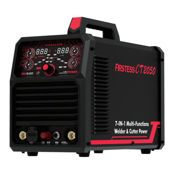
- Page 1 MULTl-PROCESS IGBT INVERTER WELDER & CUTTER(AC/DC TIG, AC/DC PULSE TIG, STICK, PLASMA CUT WITH OUTER AIR AND BUILT-IN AIR) OPERATOR'S MANUAL Copyright © YesWelder Please read this manual before using your new CT2050 welding and cutting machine...
- Page 2 Congratulations on your new YesWelder product! YesWelder creates quality products at dis- counted prices to make welding affordable to everyone. To help us serve you better and for further questions, visit www.yeswelder.com. Thank you for your purchase.
-
Page 3: Table Of Contents
TABLE OF CONTENTS SAFETY ·············································································································· 01-04 SYMBOL EXPLANATION ··························································································· 05 PRODUCT OVERVIEW ······························································································· 06 FUNCTION OVERVIEW ······························································································ 07 PERFORMANCE CHARACTERISTICS ········································································· 08 INSTALLATION ········································································································ 09 ACCESSORIES ········································································································· 10 DESCRIPTION ····································································································· 11-18 OPERATION ······································································································· 19-34 CAUTION ················································································································ 35 BASIC KNOWLEDGE OF WELDING ········································································ 36-43 OPTIONAL ACCESS OPERATION DESCRIPTION ·······························································... -
Page 4: Safety
SAFETY DEPENDS ON YOU If you de develop unusual symptoms, see your supervisor. Per- YESWELDER arc welding and cutting equipment are designed haps the welding atmosphere and ventilation system should be and built with safety. However, your overall safety can be in- checked. - Page 5 SAFETY If fuel is spilled, wipe it up and do not start engine until fumes have been eliminated. WARNINGS 1.d. Keep all equipment safety guards, covers and devices in position and in good repair. Keep hands, hair, clothing and tools away from V- belts, gears, fans and all other moving CALIFORNIA PROPOSITION 65 WARNINGS parts when starting, operating or repair-...
- Page 6 SAFETY ELECTRIC SHOCK ARC RAYS CAN BURN. CAN KILL. 3.a. The electrode and work (or ground) cir- 4.a. Use a shield with the proper filter and cover plates to pro- cuits are electrically “hot” when the tect your eyes from sparks and the rays of the arc when welder is on.
- Page 7 SAFETY CYLINDER MAY EXPLODE IF WELDING AND CUTTING DAMAGED. SPARKS CAN CAUSE FIRE OR EXPLOSION. 7.a. Use only compressed gas cylinders con- taining the correct shielding gas for the process used and properly operating reg- ulators designed for the gas and pres- 6.a.
-
Page 8: Symbol Explanation
SYMBOL EXPLANATION WARNING Cautions in Operation Power ON Power OFF Items Need Special Instruction It’s forbidden to dispose electric waste to- gether with other ordinary waste. Please Ground Connection take care of our environment. SMART Function Arc force current Input Voltage Current Remote Control Mode Frequency... -
Page 9: Product Overview
The integration of a unique elec- tric structure with an air channel design in the CT2050 series can speed up the heat dissipation of the power device, so that to im- prove the duty cycle. -
Page 10: Function Overview
FUNCTION OVERVIEW Multi Functions Design Multiple welding process: AC/DC TIG, AC/DC Pulse TIG, Stick Welding, Plasma Cutting with outer air or with built-in compres- Ÿ sor air. Remote control available: able to use pedal remoter and welding torch to torch on/off and welding amperage. Ÿ... -
Page 11: Performance Characteristics
PERFORMANCE CHARACTERISTICS IGBT inverter technology The adoption of 42 kHz inverting frequency and strong shock resistance IGBT for the main loop contributes to smaller welder size Ÿ and lighter weight, and higher reliability. A great reduction in copper and core loss greatly enhances welding efficiency and saves energy. Ÿ... -
Page 12: Installation
SELECT SUITABLE LOCATION 68V(with 110V STICK 10~160A 20.4~26.4V VRD 7V) Locate the CT2050 in a dry place with free clean air circulation to minimize the chance of dirt accumulation that can block air 312V 12~25A 84.8~90V passages and cause overheating. OTHER PARAMETERS Power ... -
Page 13: Accessories
ACCESSORIES 1. 13' M-IPL-50 Non-HF Cutting Torch (M16*1.5 Gas&Electric Connector) 2. 13' M-WP-26 TIG Torch with Amperage Control (KDP35-50 Electric Connector, M16*1.5 Gas Connector, 5-pin Control Cable) 3. 8' Gas Hose with 5/8"-18 RH 4. 13' Air Tube 5. Air Compressor Regulator Filter 6. -
Page 14: Description
DESCRIPTION Panel Controls 1. Operation Panel: Permits function selection and parameters 8. Trademark setting 9. Handle 2. Positive Output Receptacle: Permits attaching a work lead 10. CNC Arc Voltage Connector 3. Torch Connector: Permits attaching the TIG gas connec- 11. CNC Signal Control Connector tor/CUT torch 12. - Page 15 DESCRIPTION Panel Description 1. Weld Process Selection 2. Torch Operation Selection 3. Digital Display 4. Pulse Indicator 5. VRD Indicator 6. Input Voltage 7. Welding Angle Selection 8. Al Thickness 9. Smart Mode Selection 10. Parameter Indicators Fig 1 Panel Function Fig 2 Digital Display Fig 3 Input Voltage 1.
- Page 16 DESCRIPTION Fig 6 SMART Selection-Angle Fig 7 SMART Selection-Thickness 1. Welding Angle Selection 1. Aluminum Thickness-Selectection 2. Flat 2. 18GA 1.0mm 3. Vertical 3. 16GA 1.3mm 4. Overhead 4. 14GA 1.6mm 5. 1/8" 3.2mm 6. 3/16" 5.0mm Fig 8 SMART Selection 1.
- Page 17 DESCRIPTION Keys Operation Description Welding Process Selection Press when there is no load; can choose a different welding mode based on actual demands; this button is invalid in the middle of welding; the mode switch will roll when the welder goes back to no-load status. Please see the description below: AC TIG DC TIG Stick...
- Page 18 DESCRIPTION SMART Mode Selection AC TIG When under AC/AC, Pulse TIG mode, press to select "SMART" mode. Please see below: SMART AC TIG AC TIG SMART SMART SMART OFF SMART ON Fig 13 Operation Selection When under SMART mode, one can press to select different welding angles according to actual application: Flat Welding Angle Vertical Welding Angle...
- Page 19 DESCRIPTION Welding Parameters Setting Press rotary encoder potentiometer to adjust welding parameters based on actual demands. The parameters’ setting can be done during no load or in the middle of welding without affecting welding. Welding Torch Switch Initial Up Slope Background Pulse Pre-flow...
- Page 20 DESCRIPTION Torch Switch Arc Force Down Slope Clearance Welding Mode Crater Current Post-flow AC Frequency Mode Current Time Width ● × × × × × Stick × × ● ● ● × × ● ● ● × × DC TIG ×...
- Page 21 DESCRIPTION MODEL: CT2050 ANSI/IEC STD.60974-1 =110V =220V 5A/10.2V~160A/16.4V 5A/10.2V~200A/18V 100% 100% 20~250Hz 160A 200A =68V 16.4V =110V =220V 10A/20.4V~160A/26.4V 10A/20.4V~200A/28V 160A 200A =68V 26.4V =110V =220V 12A/84.8V~25A/90V 12A/84.8V~45A/98V 100% 100% =312V =47A =36A =110V 1 max 1 eff =220V =31A...
-
Page 22: Operation
OPERATION Set Up for TlG Welding (GTAW) WARNING: TIG TORCH IS ALWAYS LIVE (ELECTRICALLY HOT). Use caution and ensure the TIG torch is not in contact with or close to a conductive or grounded material. Note: REMOVE ALL THE COLLECTION FROM THE POSITIVE(+) , NEGATIVE(-) OUTPUT RECEPTACLE, AND TORCH CONNECTOR. - Page 23 Torch Assembling Match Collet and Collet Body size tungsten electrode. Ÿ Thread the Collet Body into the front of the Torch. Ÿ Match the size of the Ceramic Nozzle to shielding gas requirements for workpiece material thickness (see Settings Chart). Thread Ÿ...
- Page 24 1. Cermic Gas Nozzle 2. Collets Body 3. Collet 4. Insulator Torch Body 5. Torch Head 6. Back Cap Current Ranges Recommendation for Tungsten Electrodes Recommended Welding Current Electrode Dia. DCEN(A) AC (A) 1/16" 70-150 60-120 3/32" 150-250 100-180 1/8" 250-400 160-250 5/32"...
- Page 25 TIG Electrodes Specification Reference Table Settings Chart Material Tungsten Tungsten Filler Filler Metal Ceramic Gas Flow Material Amps Gaas Flow Thickness Color Dia. Metal Diameter Nozzle size Rate(SCFH) Grey, Orange, Mild Steel 1/16" 55~90 1/16" ER70S-2 1/16" 11-12 Red, White Grey, Orange, Mild Steel 1/32"...
- Page 26 DC TIG Parameters Process Parameter Description 220V 110V Default PRE GAS Pre-flow 0.1~15s 0.1~15s 0.3s Istart Initial Current 5~160A 5~80A SLOPE UP UpSlope Time 0~10s 0~10s DC TIG Peak Current 5-200A 5~160A SLOPPE DOWN Downslope Time 0~15s 0~15s Istop Crater Current 5~200A 5~100A POST GAS...
- Page 27 AC Square Wave TIG Welding I0-Initial Current, I1-Welding Current, I2-Pilot Arc Current, tu-Upslope Time, td-Downslope Time tp-AC Period, tc-Cathode Current Time Fig 16 AC Square Wave TIG Current Change Waveform In AC square wave TIG welding, the pre-flow time and post-flow time are the same with those in DC TIG welding, and others are de- scribed as below.
- Page 28 AC Pulse TIG Welding tc-Cathode Current time, tp-AC Period Tp-Pulsed Peak Current Time, T-Pulse Period Fig 17 AC Pulse TIG Current Change Waveform AC pulse TIG welding is almost the same as AC square wave TIG welding, and what makes them different is that in AC pulsed TIG welding, the welding current varies with the pulse, peak current, and base current is generated because the welding current is con- trolled by a low-frequency pulse.
- Page 29 SMART Function Smart Set makes welding easy by taking the guesswork out of AC TIG welding settings. Simply select welding angle ( flat, vertical, or overhead) and Aluminum thickness; the machine will recommend the ideal parameters such as amperage, preflow, post flow, upslope time, downslope time, AC balance, etc.
- Page 30 Set Up for Plasma Cutting Connect the Cutting torch to the Torch Connector. Ÿ Plug the 5-pin torch control switch cable into to Trigger Connector Receptacle. Ÿ Connect the work clamp to the Positive(+) Output Receptacle, ensure it has good contact with the workpiece on a clean, bare Ÿ...
- Page 31 Cutting Torch Assembly Plasma Cutting Torch Accessory 1. Spacer Guide 2. Outside Nozzle 6 holes 3. Nozzles Tips 4. Electrodes 5. Diffuser 6. Torch Head...
- Page 32 Installation for Air Pressure Compressor Filter Regulator YesWelder CT2050 could support plasma cutting with built-in compressor air and plasma cutting with outer air from an external com- pressor. The built-in compressor makes it easy to take on various outdoor projects, and making life for welders on the road that much easier.
- Page 33 With External Air Compressor Connection for Air Compressor Filter Regulator with an External Compressor Loose the fixing nuts on the rear panel to install the bracket. Ÿ Place the air filter regulator on the bracket and fix it. Ÿ Connect the Inlet-Air In with the filter regulator outlet nozzle by an air tube and tighten it with a clamping band. Ÿ...
- Page 34 CNC Setting YesWelder CT2050 is suitable for CNC automatic cutting and have CNC interface port. Great for making precision cuts that are im- possible to get with a hand-held tool in auto repair, machine fabrication, and construction. Back Connection CNC Voltage Connector: 2-pin control socket, connection of CNC communication signals showing arc voltage output, pin1 is positive, pin 2 is negative, com- patible with CNC table with ARC voltage feedback ratio 1:1.
- Page 35 General Technical Parameters Process Parameter Description 220V 110V Default PRE GAS Pre-flow 0.1~15s 0.1~15s 0.5s Istart Initial Current 10~25A 10~25A SLOPE UP UpSlope Time 0~10s 0~10s Peak Current 12-45A 12~25A SLOPPE DOWN Downslope Time 0~15s 0~15s Istop Crater Current 10~25A 10~25A POST GAS Post-flow...
- Page 36 Set Up for Stick Welding (SMAW) Remove all the connection from the Positive(+) or Negative (-) Output Receptacle (Remove the TIG torch at the same time.) Ÿ Check the electrode packaging to determine the recommended polarity and connect the electrode stringer and work clamp to the Ÿ...
- Page 37 YesWelder CT2050 has a VRD feature embedded in this welder and activates when the welder is on. It reduces the voltage of the open circuit to a safer level, thus reducing the chances of electric shock in case the wrong connection is for cutting the torch when the OCV is high in Cutting.
-
Page 38: Caution
CAUTION Working Environment 1. Welding should be carried out in a dry environment with humidity of 90% or less. 2. The working environment temperature should be between -10°C and 40°C. 3. Avoid welding in the open air unless sheltered from sunlight and rain. Keep the welder dry. 4. -
Page 39: Basic Knowledge Of Welding
BASIC KNOWLEDGE OF WELDING Basic Knowledge of Stick Manual metal arc welding (MMA/Stick) is arc welding by manually operating electrodes. Stick requires simple equipment and is a convenient, flexible, and adaptive welding processing type. Stick is applied to various metal materials with thicknesses of more than 2mm. - Page 40 BASIC KNOWLEDGE OF WELDING a) Flat Welding b) Vertical Welding Fig 19 Posture in Welding 3) Arc Igniting Arc igniting is the process of producing a stable arc between electrode and workpiece in order to heat them to implement welding. Common arc ignition mode includes scraping mode and striking mode.
- Page 41 BASIC KNOWLEDGE OF WELDING electrode welding direction welding direction electrode workpiece workpiece 1. downwards feed 2. move toward welding direction 3. transversely swing Fig 21 Three basic movement directions of electrode Fig 22 Angles of electrode in flat welding 6) Arc Extinguishing Arc extinguishing is unavoidable during welding.
- Page 42 BASIC KNOWLEDGE OF WELDING Nozzle Molten pool Tungsten electrode Filler wire Shield gas Weld bead Fig 24 Sketch Map of Argon Arc Welding Since argon is a kind of inert gas and it does not react with metals, the alloying elements in the weld metal will not be burned out and the metal molten pool can be fully protected from oxidation.
- Page 43 BASIC KNOWLEDGE OF WELDING GTAW Process 1. Preweld cleaning Clean the electrode and the zone near the weld joint of the workpiece, and remove impurities such as oil pollution and the oxidized film on the surface of the metal before carrying out argon arc welding to ensure good quality of weld bead. The methods for preweld cleaning are: mechanical cleaning, chemical cleaning and chemical &...
- Page 44 BASIC KNOWLEDGE OF WELDING In addition, the gas protective effect can be judged by directly observing the color of the weld bead surface. Take stainless steel welding for example. If the weld bead surface appears silvery white or golden, it indicates that the gas protective effect is good. However, if the weld bead surface appears gray or black, it indicates that the gas protective effect is poor.
- Page 45 BASIC KNOWLEDGE OF WELDING Basic Knowledge of CUT General Description of CUT (Plasma Cutting) 1. Economic and practical, since it can cut metals by adopting compressed air as the plasma gas source. 2. The cutting speed has increased by 1.8 times when compared with oxyacetylene cutting. 3.
-
Page 46: Optional Access Operation Description
BASIC KNOWLEDGE OF WELDING The workpiece is not cut fully. This may be caused by: The cutting current is too low. The cutting speed is too high. The electrode and nozzle of the torch are burned. The workpiece is too thick. Molten slag drops from the bottom of workpiece. - Page 47 Wire-drive Welding Torch Operation YesWelder CT2050 is equipped with an analog control wire-drive welding torch . Current Regulation potentiometer Torch Switch Pulse Analog Regulation Type Fig 29 Wire-drive welding torch is usually applied while it’s under TIG. Connect the wire-drive torch to the welder front panel pedal controller connection aviation socket through dedicated cable. See Fig Ÿ...
-
Page 48: Maintenance
MAINTENANCE GENERAL MAINTENANCE This welder has been engineered to need minimal service providing that a few very simple steps are taken to properly maintain it. 1. Keep the cabinet cover closed at all times unless the wire needs to be changed or the drive pressure needs adjusting. 2. - Page 49 Look under the column labeled "PROBLEM cause, If you do not understand or are unable to perform the (SYMPTOMS)". This column describes possible symptoms that Recommended Course of Action safely, contact YESWELDER the machine may exhibit. Find the listing that best describes the support@yeswelder.com.
- Page 50 TROUBLESHOOTING TIG WELDING ISSUES PROBLEM POSSIBLE CAUSE COURSE OF ACTION Poor work clamp connection. Check and secure work connection. Poor starting. Start current is too low. Increase Start current. Oily or organic contamination on work Clean work piece. Tungsten electrode may be contaminated. Grind to clean electrode.
- Page 51 TROUBLESHOOTING TIG WELDING ISSUES PROBLEM POSSIBLE CAUSE COURSE OF ACTION Check the gas is connected and cylinder valve open, check No gas, incorrect gas flow. hoses, gas valve and torch are not restricted. Set the gas flow between 20-30 cfh flow rate. Poor work clamp connection.
- Page 52 Examine the consumables for wear and replace worn parts Plasma torch parts are worn out. with new YesWelder consumable parts. Use only genuine YesWelder consumables for optimum per- Non-genuine manufacturer's parts. formance. Check for obstructions blocking air flow and ensure that there are 12 inches of clearance between any obstacles Insufficient air flow or pressure.
- Page 53 Examine the consumables for wear and replace worn parts Plasma torch parts are worn out. with new YesWelder consumable parts. Use only genuine YesWelder consumables for optimum per- Non-genuine manufacturer's parts. formance. Inspect air compressor, air lines, and filters for proper oper- ation.
- Page 54 TROUBLESHOOTING STICK WELDING ISSUES PROBLEM POSSIBLE CAUSE COURSE OF ACTION Poor starting. Poor work clamp connection. Check and secure work connection S t i c k e l e c t r o d e Current may be set too high for electrode "blasts off"...
- Page 55 15. WIRING DIAGRAM...
- Page 56 V2.01...
Need help?
Do you have a question about the CT2050 and is the answer not in the manual?
Questions and answers