
Related Manuals for Yeswelder YWM-211P


Summary of Contents for Yeswelder YWM-211P
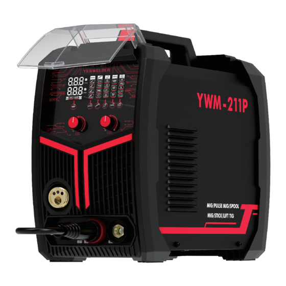
- Page 1 YWM-211P IGBT INVERTER MULTI-PROCESS WELDER (MIG, PULSED MIG, SPOOL GUN COMPATIBLE MIG, STICK, LIFT TIG) Aug., 2023 OPERATOR’S MANUAL Copyright © YesWelder...
- Page 3 Congratulations on your new YesWelder product! We at YesWelder create quality products at dis- counted prices to make welding affordable to everyone. To help us serve you better and for further questions, visit www.yeswelder.com. Thank you for your purchase.
-
Page 4: Table Of Contents
TABLE OF CONTENTS SAFETY································································································································1-4 INSTALLATIONS····················································································································5 ACCESSORIES······················································································································6 DESCRIPTION······························································································································ 7-11 Controls And Settings·················································································································8-13 Installing The MIG Gun Assembly·································································································11 Gas Cylinder And Regulator Connection·······················································································11 Installing The Welding Wire······································································································11-13 OPERATION································································································································13-25 Performance Data Plate And Duty Cycle··················································································13-14 Welding Preparation······················································································································14 Welding Wire Selection··················································································································15 Gas Selection·································································································································15 Set up for MIG Welding (GMAW)···························································································15-23 Set up for Lift Arc TIG Welding (GTAW)························································································23 Set up for Stick Welding (SMAW)····························································································24-25 MAINTENANCE &... -
Page 5: Safety
SAFETY DEPENDS ON YOU If you develop unusual symptoms, see your supervisor. Per- YESWELDER arc welding and cutting equipment are designed haps the welding atmosphere and ventilation system should be and built with safety. However, your overall safety can be in- checked. - Page 6 SAFETY If fuel is spilled, wipe it up and do not start engine until fumes have been eliminated. WARNINGS 1.d. Keep all equipment safety guards, covers and devices in position and in good repair. Keep hands, hair, clothing and tools away from V- belts, gears, fans and all other moving CALIFORNIA PROPOSITION 65 WARNINGS parts when starting, operating or repair-...
- Page 7 SAFETY ELECTRIC SHOCK ARC RAYS CAN BURN. CAN KILL. 3.a. The electrode and work (or ground) cir- 4.a. Use a shield with the proper filter and cover plates to pro- cuits are electrically “hot” when the tect your eyes from sparks and the rays of the arc when welder is on.
- Page 8 SAFETY CYLINDER MAY EXPLODE IF WELDING AND CUTTING DAMAGED. SPARKS CAN CAUSE FIRE OR EXPLOSION. 7.a. Use only compressed gas cylinders con- taining the correct shielding gas for the process used and properly operating reg- ulators designed for the gas and pres- 6.a.
-
Page 9: Installations
Mode Voltage Current Range Voltage Range SELECT SUITABLE LOCATION GMAW 30A~200A 15.5V~24V Locate the YWM-211P in a dry place with free clean air circula- 220V SMAW 20A~180A 20.8V~27.2V tion to minimize the chance of dirt accumulation that can block GTAW 10A~200A 10.4V~18V... -
Page 10: Accessories
ACCESSORIES 1. Welder 5. 220V~110V Power Plug 2. Work Clamp 6. 24KD MIG Gun 3. Electrode Holder 7. Graphene Feeding Liner 4. V Knurl Groove 8. Contact Tips (.4pieces) Drive Roller: .023"/.0 9. Gas Hose 30" (.030" & .035" on 10. -
Page 11: Description
DESCRIPTION SAFETY PRECAUTIONS PRODUCT DESCRIPTION (PRODUCT CAPABILITIES) Read entire operation section before operating This small portable wire feed welder is capable of MIG (GMAW/ the WIRE FEEDER WELDER. on steel, mild steel, stainless steel. The wire feed welder is also WARNING capable of STICK welding (SMAW) and DC lift TIG welding (GTAW). -
Page 12: Controls And Settings
Controls And Settings .045" AlSi 1.2mm Arclong AlMg .035" 0.9mm .030" 0.8mm m/min .023" 0.6mm MENU 1. Function / Voltage Adjustment / Gas Checking Knob: Permits selecting Gas Pre-Flow, Post-Flow, Inductance, Rin, Hot start, Burn back time, Spot time in MIG and Pulsed MIG Mode, Synergy or Manual MIG in MIG Mode, Pulse / Double-Pulse Pulsed MIG Mode, IBS, FRQ, Duty cycle in Double-Pulse MIG Mode, Arc force, Hot start, VRD, and Anti-stick in Stick Mode. - Page 13 3 4 5 6 7 10. Wire Drive Polarity Lead-Permits configuring the wire drive to positive or negative polarity by inserting it into the positive or negative receptacle. Ensure the connector is locked into place tightly by turning clockwise. 11. Gun Connection (Euro Connect)-Permits attachment of a MIG welding gun. Ensure the gun is fully seated into the brass receptacle.
- Page 14 19. Wire Spool Spindle and Brake: Holds a 4-inch diameter spool. Use the 2-inch ID spindle adapter included with the machine to run an 8-inch diameter spool. The user can set the brake’s friction load through the Wing Nut to prevent the spool from over- rotating when the trigger is released.
-
Page 15: Installing The Mig Gun Assembly
Installing The MIG Gun Assembly Attach the standard MIG welding gun to the EURO CONNECT on the front of the welder. Ensure the gun connector end is seated Ÿ fully into the wire drive and tighten the thumbscrew to secure the gun. Gas Cylinder And Regulator Connection The gas cylinder (not supplied) should be located near the rear of the welder, in a well-ventilated area and securely fixed to the work bench or to the wall to ensure that it will not fall. - Page 16 Installing 4-Inch Spool (See Figure For Part Identification): Open the access panel. Ÿ Unscrew and remove the wire spool retention cap used for 8-inch spools (A) and store it someplace safe. Ÿ Remove the spindle adapter for 8-inch spools (B) and keep it someplace safe. Ÿ...
-
Page 17: Operation
Cut off the excess wire that extends past the end of the nozzle. Ÿ Fine-tune the wire drive pressure with the pressure arm adjustment knob (G). Ÿ Turn the pressure adjustment knob clockwise to increase the driving pressure until the wire seems to feed smoothly without Ÿ... -
Page 18: Welding Preparation
S/N: MODEL: YWM-211P ANSI/IEC STD.60974-1 =110V =220V 30A/15.5V~160A/22V 30A/15.5V~200A/24V 60% 100% 60% 100% 160A 123A 200A 158A =72V 22V 20.1V 24V 21.9V =110V =220V 10A/10.4V~160A/16.4V 10A/10.4V~200A/18V 60% 100% 60% 100% 160A 124A 200A 155A =72V 16.4V 15V 18V 16.2V =110V =220V 20A/20.8V~145A/25.8V... -
Page 19: Welding Wire Selection
EXPOSURE TO A WELDING ARC IS EXTREMELY HARMFUL TO THE EYES AND SKIN. PROLONGED EXPOSURE TO A WELDING ARC CAN CAUSE BLINDNESS AND BURNS. NEVER STRIKE AN ARC OR BEGIN WELDING UNLESS YOU ARE ADEQUATELY PROTECTED. WEAR FIRE RESISTANT WELDING GLOVES, HEAVY LONG SLEEVED SHIRT, CUFFLESS PANTS;... - Page 20 How To Choose Synergic MIG Synergic MIG this is a predefined setting based on Gas and wire used. The machine will preselect voltage and amperage allowing the user to quickly find the best welding parameters. Simply select the correct wire diameter and gas type that you’re using then dial in your desired wire feed speed for the job. Use more wire speed for thicker material and less wire speed for thinner material.
- Page 21 How To Choose Manual MIG Manual MIG allows separate setting for welding parameters such as the wire feed speed and voltage. Refer to weld chart along with the package for proper parameter settings according to wire type, shielding gas, and material type and thickness. 1.
- Page 22 How To Choose Pulsed MIG In Pulse MIG mode there is no manual voltage adjustment; instead, voltage is synergi cally aligned with the proper wire feed speed. Arc length can be adjusted from -3~3V. Arc Length adjustment is used to adjust actual arc length which automatically adjusts the voltage from -3V to +3V.
- Page 23 Note: In 4T mode, it’s able to adjust the stop amperage and voltage, while the 4TL could adjust stop amperage and voltage, at the same time, start amperage and voltage. Initial current (I1), welding current (I) & pilot arc current (l2): The preset value of the three parameters is approximately the absolute average of the practical welding current, and can be adjusted according to user’s technical requirements.
- Page 24 Set up for Aluminum Welding With Spool Gun Install optional YesWelder LBT150 spool gun into Euro MIG torch connection socket on the front panel, and tighten it. Connect the Ÿ Spool Gun control cable to the receptacle and tighten it.
- Page 25 Install optional YesWelder LBT150 spool Push the Cover Release clip on the Ÿ Ÿ Place the wire on the spool holder, tak- Ÿ gun into Euro MIG torch connection spool gun to unlock the wire housing ing care to put the parts back on cor- socket on the front panel, and tighten it.
- Page 26 Remove the MIG torch consumables. Remove the liner retaining nut. Ÿ Ÿ Pull out the liner completely Ÿ Untie the new liner. Feed the liner in short forward move- Ÿ Ÿ Reassemble the accessories. Ÿ ments down the cable assembly all the way through and out the torch end.
-
Page 27: Set Up For Lift Arc Tig Welding (Gtaw)
5. Load the memorized channel number for recalling the welding parameters. Set up for Lift Arc TIG Welding (GTAW) Setting up the Equipment for TIG Welding (GTAW): TIG torch is not included, additional YesWelder WP-17V-35 Lift TIG torch and Lanthanated Tungsten are recommended for use. -
Page 28: Set Up For Stick Welding (Smaw)
Set up for Stick Welding (SMAW) Remove the Wire Drive Polarity Lead form the POSITIVE (+) or NEGATIVE (-) SOCKETS (Remove the MIG torch at the Ÿ same time). Check the electrode packaging to determine the recommended polarity and connect the electrode stringer and work clamp Ÿ... - Page 29 Arc Force Adjustable: Arc force is a momentarily increase of the welding current during welding when the machine senses the drop of the arc voltage caused by a short arc length. Arc force compensates for the voltage drop by increasing the amperage. Increased amperage en- sures that the heat stays the same and that the electrode will not dip into the base metal.
-
Page 30: Maintenance & Servicing
MAINTENANCE & SERVICING General Maintenance This welder has been engineered to need minimal service providing that a few very simple steps are taken to properly main- tain it. Keep the cabinet cover closed at all times unless the wire needs to be changed or the driving pressure needs adjusting. Ÿ... -
Page 31: Troubleshooting
If you do not understand or cannot perform the Recom- column describes the sign that the machine is showing. Find the mended Course of Action safely, contact YESWELDER sup- listing that best describes the symptom that the machine is exhib- port@yeswelder.com. - Page 32 TROUBLESHOOTING MIG WELDING ISSUES PROBLEM POSSIBLE CAUSE COURSE OF ACTION Pull the trigger while in contact with the workpiece. The Gun trigger is not being pulled or is not machine does not arc unless the trigger is pulled. Depress making contact. the trigger ALL THE WAY until the trigger stops moving into the gun.
- Page 33 TROUBLESHOOTING MIG WELDING ISSUES PROBLEM POSSIBLE CAUSE COURSE OF ACTION No pressure on the drive roller; insufficient or excessive pressure on the Adjust the drive pressure. Arc works but not drive roller. feeding wire. Wire spool is empty. Check if wire is in place and replace if necessary. Adjust the drive pressure.
- Page 34 TROUBLESHOOTING TIG WELDING ISSUES PROBLEM POSSIBLE CAUSE COURSE OF ACTION Poor work clamp connection. Check and secure work connection. Poor starting. Start current is too low. Increase Start current. Oily or organic contamination on work Clean work piece. Tungsten electrode may be contaminated. Grind to clean electrode.
- Page 35 TROUBLESHOOTING TIG WELDING ISSUES PROBLEM POSSIBLE CAUSE COURSE OF ACTION Check the gas is connected and cylinder valve open, check No gas, incorrect gas flow. hoses, gas valve and torch are not restricted. Set the gas flow between 20-30 CFH flow rate. Poor work clamp connection.
- Page 36 TROUBLESHOOTING STICK WELDING ISSUES PROBLEM POSSIBLE CAUSE COURSE OF ACTION Poor starting. Poor work clamp connection. Check and secure work connection S t i c k e l e c t r o d e Current may be set too high for electrode “blasts off”...
-
Page 37: Operation Code
OPERATION CODE VOLTAGE(V) POST-GAS GAS-CHECKING SYNERGIC FREQUENCE SPOT TIME MIG SETTING INCHING DUTY CYCLE ARC START CURRENT END ARC CURRENT DOUBLE PULSED ARC FORCE PRE-GAS ANTI-STICK - 33 -... -
Page 38: Wiring Diagram
WIRING DIAGRAM - 34 -... - Page 40 WE ALWAYS STAND BEHIND IT Toll Free (855) 937-4567...
Need help?
Do you have a question about the YWM-211P and is the answer not in the manual?
Questions and answers