
Related Manuals for Yeswelder MIG-250PRO


Summary of Contents for Yeswelder MIG-250PRO
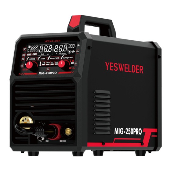
- Page 1 MIG-250PRO IGBT INVERTER MULTI-PROCESS WELDER (MIG, FLUX-CORED, STICK, LIFT TIG) OPERATOR’S MANUAL Copyright © YesWelder...
-
Page 3: Table Of Contents
TABLE OF CONTENTS SAFETY ················································································································································ 01 - 05 INSTALLATION ···································································································································· 06 - 07 TECHNICAL SPECIFICATIONS ··············································································································· 06 SAFETY PRECAUTIONS ························································································································· 07 FUMES AND GASES CAN BE DANGEROUS ························································································· 07 WELDING SPARKS CAN CAUSE FIRE OR EXPLOSION ····································································· 07 ARC RAYS CAN BURN EYES AND SKIN ·······························································································07 ACCESSORIES ···········································································································································... -
Page 4: Safety
SAFETY DEPENDS ON YOU YESWELDER arc welding and cutting equipment are designed and built with safety. However, your overall safety can be increased by proper installation and thoughtful operation on your part. DO NOT INSTALL, OPERATE OR REPAIR THIS EQUIPMENT WITH- OUT READING THIS MANUAL AND THE SAFETY PRECAUTIONS CONTAINED THROUGHOUT. - Page 5 SAFETY WARNING CALIFORNIA PROPOSITION 65 WARNINGS WARNING: Breathing diesel engine exhaust exposes you to chemicals known to the State of California to cause cancer and birth defects, or other reproductive harm. Always start and operate the engine in a well-ventilated area. Ÿ...
- Page 6 SAFETY ELECTRIC AND MAGNETIC FIELDS MAY BE DANGEROUS. 2.a. Electric current flowing through any conductor causes localized Electric and Magnetic Fields (EMF). Welding current creates EMF fields around welding cables and welding machines 2.b. EMF fields may interfere with some pacemakers, and welders having a pacemaker should consult their physician before weld- ing.
- Page 7 SAFETY FUMES AND GASES CAN BE DANGEROUS. 5.a. Welding may produce fumes and gases hazardous to health. Avoid breathing these fumes and gases. When welding, keep your head out of the fume. Use enough ventilation and/or exhaust at the arc to keep fumes and gases away from the breathing zone.
- Page 8 SAFETY CYLINDER MAY EXPLODE IF DAMAGED. 7.a. Use only compressed gas cylinders containing the correct shielding gas for the process used and properly operating regulators designed for the gas and pressure used. All hoses, fittings, etc. should be suitable for the application and maintained in good condition.
-
Page 9: Installation
SELECT SUITABLE LOCATION Locate the MIG-250PRO in a dry location where there is free circulation of clean air into the louvers in the back and out the front of the unit. A location that minimizes the chance of dirt accumulation that can block air passages and cause overheating. -
Page 10: Safety Precautions
INSTALLATION SAFETY PRECAUTIONS Read entire operation section before operating the WIRE FEEDER WELDER. WARNING ELECTRIC SHOCK CAN KILL. Do not touch electrically live parts such as output terminals or internal wiring. Ÿ Insulate yourself from the work and ground. Ÿ Always wear dry insulating gloves. -
Page 11: Accessories
ACCESSORIES Welder Ground Clamp Electrode Stringer V Knurl Groove Drive Roller: .023'' & .030'' W Knurl Groove Drive Roller: .030" & .035" U Knurl Groove Drive Roller: .035" & .045" V Knurl Groove Drive Roller: .030'' & .035'' (on the machine) MIG Gun MIG Gun Tips X 4 Graphene Feeding Liner... -
Page 12: Operation
OPERATION CONTROLS PANEL FUNCTIONS OF MIG-250PRO Digital Panel Euro Torch Socket Wire Drive Polarity Lead Spool Gun Socket Positive (+) Output Terminal Negative (-) Output Terminal Power Switch Gas Inlet Input Power Cable - 09 -... - Page 13 OPERATION Wire Diameter Selector Button For selecting the welding wire diameter: .023''/.030''/.035''/.045''. 2T/4T Selector Button For selecting the 2T/4T mode (Only available in MIG mode). Weld Mode Selector Button For selecting the welding mode: Lift TIG/Stick/Manual MIG/Synergic MIG. Spool Gun Switch Button For turning on/off the spool gun connection (Only available in Manual MIG mode).
-
Page 14: Installing The Mig Gun Assembly
OPERATION INSTALLING THE MIG GUN ASSEMBLY • Attach the standard MIG welding gun to the EURO CONNECT on the front of the welder. GAS CYLINDER AND REGULATOR CONNECTION The gas cylinder (not supplied) should be located near the rear of the welder, in a well-ventilated area and securely fixed to the work bench or to the wall to ensure that it will not fall. -
Page 15: Installing 4-Inch Spool (See Figure For Part Identification)
OPERATION INSTALLING 4-INCH SPOOL (SEE FIGURE FOR PART IDENTIFICATION) 1. Open the access panel. 2. Unscrew and remove the wire spool retention cap used for 8-inch spools (A) and store it someplace safe. 3. Remove the spindle adapter for 8-inch spools (B) and store it someplace safe. 4. -
Page 16: Performance Data Plate And Duty Cycle
OPERATION 12. Cut off the excess wire that extends past the end of the nozzle. 13. Fine tune the wire drive pressure with the pressure arm adjustment knob (G). a. Turn the wire drive pressure adjustment knob clockwise, increasing the drive pressure until the wire seems to feed smoothly without slipping. -
Page 17: Internal Thermal Protection
OPERATION INTERNAL THERMAL PROTECTION If you exceed the duty cycle of the welder, the thermal protection system will engage, shutting off all welder output. After cooling, the thermal protector will automatically reset and the welding functions can resume. This is normal and automatic behavior of the ma- chine, and does not require any user action. -
Page 18: Welding Wire Selection
OPERATION EXPOSURE TO A WELDING ARC IS EXTREMELY HARMFUL TO THE EYES AND SKIN. PROLONGED EXPOSURE TO A WELDING ARC CAN CAUSE BLINDNESS AND BURNS. NEVER STRIKE AN ARC OR BEGIN WELDING UNLESS YOU ARE ADEQUATELY PROTECTED. WEAR FIRE RESISTANT WELDING GLOVES, HEAVY LONG SLEEVED SHIRT, CUFFLESS PANTS;... -
Page 19: Setup For Mig (Gmaw) & Flux-Cored Wire (Fcaw) Welding
OPERATION MIG Parameter Range Output Voltage Inducta Input WFS Range Weld Mode Material/Gas Wire Dia. Voltage Fine Tune Pulse Voltage (in/min) Range Range Range .023'' 202~858 FE (100% CO .030'' 124~858 .035'' 124~780 .023'' 202~858 FE/SS (MIX .030'' 124~858 GAS) Manual MIG 12~26V -10~+10... - Page 20 OPERATION Load the spool of wire inside the cabinet and feed it through the wire feeder into the gun (see “Installing the Welding Wire” Ÿ section). Turn the machine on with the on/off switch. Ÿ Press the gun trigger or the button “INCHING” on the panel to load the wire through the gun. Ÿ...
- Page 21 OPERATION 2. Synergic MIG welding: Select welding mode on “Synergic MIG” by pressing the weld mode selector button. Select material on “FE/SS/AL/FLUX” by pressing the gas selector button. ‚ Select material thickness on “.023/.030/.035/.045” by pressing the wire diameter selector button. ƒ...
- Page 22 (GMAW only) Turn on the gas cylinder, pull the trigger or press gas checking button to check for gas flow and adjust the Ÿ flow rate. Bring the gun close to the workpiece and press the trigger and then start welding. Ÿ...
-
Page 23: Setup For Aluminum Welding With Spool Gun
SETUP FOR ALUMINUM WELDING WITH SPOOL GUN 1. Install optional YESWELDER spool gun into Euro MIG torch connection socket on the front panel, and tighten it. Connect the spool gun control cable to the receptacle and tighten it. -
Page 24: Operation
18. Turn on the gas cylinder valve and set the flow rate to between 10~30 CFH. 19. Begin aluminum welding with spool gun. 1. Install YESWELDER LBT150 or other 2. Open the cover and replace the 3. Remove the gas nozzle and contact tip spool gun with Euro connector into MIG matched wire feeder wheel (U Type). - Page 25 OPERATION Note: remove any burr that may obstruct wire feed. Put the gun back on the machine and tighten it, the liner will be just very close to the wire feeder roller but without touching (FIG- Ÿ 12). Cut another section of liner from the excess graphene liner to the same length as the inlet guide tube and then replace on the tube Ÿ...
-
Page 26: Setup For Stick Welding (Smaw)
OPERATION Repalce the correct size U-knurled drive Cut another section of liner from the ex- Place the tube holder back. roller. cess graphene liner to the same length as the inlet guide tube. FIG. 16 Install the matched aluminum A+ contact tip and nozzle back into the MIG gun. - Page 27 OPERATION If necessary, press the left value knob to select hot start (HS) and rotate the right value knob to adjust the value from 0~100. The Ÿ hot start function increases the amperage in the beginning, making it easier to start an arc, improving welding quality and stability. If necessary, press the left value knob again to select arc force (DIG) and rotate the right value knob to adjust the value from Ÿ...
- Page 28 OPERATION If necessary, press the left value knob again to select voltage reduction device (VRD) and rotate the right knob to turn on/off the Ÿ VRD. It is a device designed to reduce the no-load voltage of a welding machine to a safe level. If necessary, press the left value knob again to select anti-stick (ANT) and rotate the right knob to turn on/off the ANT.
-
Page 29: Setup For Tig Welding (Gtaw) With Lift Arc
OPERATION SETUP FOR TIG WELDING (GTAW) WITH LIFT ARC Setting up the Equipment for TIG Welding (GTAW): Lanthanated Tungsten recommended for use. WARNING: TIG TORCH IS ALWAYS LIVE (ELECTRICALLY HOT). Use caution and ensure the TIG torch is not in contact with or near conductive or grounded materials. -
Page 30: Maintenance&Servicing
MAINTENANCE&SERVICING GENERAL MAINTENANCE This welder has been engineered to need minimal service providing that a few very simple steps are taken to properly maintain it. 1. Keep the cabinet cover closed at all times unless the wire needs to be changed or the drive pressure needs adjusting. 2. -
Page 31: Troubleshooting
TROUBLESHOOTING The following is a troubleshooting table provided to help you determine a possible remedy when you are having a problem with your welder. This table does not provide all possible solutions, only those possibilities considered likely to be common faults. PROBLEM POSSIBLE CAUSE POSSIBLE SOLUTION... - Page 32 PROBLEM POSSIBLE CAUSE POSSIBLE SOLUTION No pressure on the drive roller; insuffi- Adjust the drive pressure. See “Installing The Welding cient or excessive pressure on the Wire”. drive roller. Arc works but not feeding wire. Wire spool is empty. Check if wire is in place and replace if necessary. Pull the trigger while in contact with the workpiece.
- Page 33 PROBLEM POSSIBLE CAUSE POSSIBLE SOLUTION Check the connection of the work clamp and gun to the machine. Check the connection of the MIG ELECTRODE POLARITY JUMPER. Check connec- Work clamp, ground tion of the ground cable to the work clamp. Tighten cable, and/or welding Bad ground or loose ground connection.
- Page 36 WE ALWAYS STAND BEHIND IT Toll Free (855) 937-4567 V1.01...
Need help?
Do you have a question about the MIG-250PRO and is the answer not in the manual?
Questions and answers