Advertisement
SAFETY
PLEASE EXAMINE THE PACKING BOX AND EQUIPMENT FOR DAMAGE IMMEDIATELY
When this equipment is shipped, the title passes to the purchaser upon receipt by the carrier. Consequently, claims for material damaged in shipment must be filed by the purchaser against the transportation company when the shipment is received.
SAFETY DEPENDS ON YOU
YESWELDER arc welding and cutting equipment are designed and built with safety. However, your overall safety can be increased by proper installation and thoughtful operation on your part. DO NOT INSTALL, OPERATE OR REPAIR THIS EQUIPMENT WITHOUT READING THIS MANUAL AND THE SAFETY PRECAUTIONS CONTAINED THROUGHOUT. And most importantly, think before you act and be careful.

This statement appears where the information must be followed precisely to avoid serious personal injury or loss of life.

This statement appears where the information must be followed to avoid minor personal injury or damage to this equipment.
KEEP YOUR HEAD OUT of THE FUMES.
DON'T get too close to the arc. Use corrective lenses if necessary to stay a reasonable distance from the arc.
READ and obey the Safety Data Sheet (SDS) and the warning label on all welding materials containers.
USE ENOUGH VENTILATION or exhaust at the arc, or both, to
keep the fumes and gases from your breathing zone and the general area.
IN A LARGE ROOM OR OUTDOORS, natural ventilation may be adequate if you keep your head out of the fumes (See below).
USE NATURAL DRAFTS or fans to keep the fumes away from your face.
If you develop unusual symptoms, see your supervisor. Perhaps the welding atmosphere and ventilation system should be checked.

WEAR CORRECT EYE, EAR & BODY PROTECTION

PROTECT your eyes and face with welding helmet properly fitted and with proper grade of filter plate (See ANSI Z49.1).
PROTECT your body from welding spatter and arc flash with protective clothing including woolen clothing, flame-proof apron and gloves, leather leggings, and high boots. PROTECT others from spatter, flash, and glare with protective screens or barriers.
IN SOME AREAS, protection from noise may be appropriate.
BE SURE protective equipment is in good condition. Also, wear safety glasses in work area AT ALL TIMES.

SPECIAL SITUATIONS
DO NOT WELD OR CUT containers Or materials which previously had been in contact with hazardous substances unless they are properly cleaned DO NOT WELD OR CUT painted or plated parts unless special precautions with ventilation have been taken They can release highly toxic fumes or gases
Additional precautionary measures:
PROTECT compressed gas cylinders from excessive heat, mechanical shocks, and arcs; fasten cylinders so they cannot fall BE SURE cylinders are never grounded or part of an electrical circuit REMOVE all potential fire hazards from welding area ALWAYS HAVE FIRE FIGHTING EQUIPMENT READY FOR IMMEDIATE USE AND KNOW HOW TO USE IT.

CALIFORNIA PROPOSITION 65 WARNINGS
Breathing diesel engine exhaust exposes you to chemicals known to the State of California to cause cancer and birth defects, or other reproductive harm.
This product, when used for welding or cutting, produces fumes or gases which contain chemicals known to the State of California to cause birth defects and, in some cases, cancer. (California Health & Safety Code § 25249.5 et seq.)
Cancer and Reproductive Harm www.P65warnings.ca.gov
ARC WELDING CAN BE HAZARDOUS. PROTECT YOURSELF AND OTHERS FROM POSSIBLE SERIOUS INJURY OR DEATH. KEEP CHILDREN AWAY. PACEMAKER WEARERS SHOULD CONSULT WITH THEIR DOCTOR BEFORE OPERATING.
Read and understand the following safety highlights. For additional safety information, it is strongly recommended you download free PDF of Standard ANSI Z49.1 from the American Welding Society. https://www.aws.org/library/doclib/AWS-Z49-2021.pdf
BE SURE THAT ALL INSTALLATION, OPERATION, MAINTENANCE AND REPAIR PROCEDURES ARE PERFORMED ONLY BY QUALIFIED INDIVIDUALS.
 FOR ENGINE POWERED EQUIPMENT.
-
- Turn the engine off before troubleshooting and maintenance work unless the maintenance work requires it to be running.
![]()
- Operate engines in open, well ventilated areas or vent the engine exhaust fumes outdoors.
- Do not add the fuel near an open flame welding arc or when the engine is running. Stop the engine and allow it to cool before refueling to prevent spilled fuel from vaporizing on contact with hot engine parts and igniting. Do not spill fuel when filling tank.
![]()
- Keep all equipment safety guards, covers and devices in position and in good repair. Keep hands, hair, clothing and tools away from Vbelts, gears, fans and all other moving parts when starting, operating or repairing equipment.
![]()
- In some cases it may be necessary to remove safety guards to perform required maintenance. Remove guards only when necessary and replace them when the maintenance requiring their removal is complete. Always use the greatest care when working near moving parts.
- Do not put your hands near the engine fan. Do not attempt to override the governor or idler by pushing on the throttle control rods while the engine is running.
If fuel is spilled, wipe it up and do not start engine until fumes have been eliminated. - To prevent accidentally starting gasoline engines while turning the engine or welding generator during maintenance work, disconnect the spark plug wires, distributor cap or magneto wire as appropriate.
- To avoid scalding, do not remove the radiator pressure cap when the engine is hot.
![]()
- Turn the engine off before troubleshooting and maintenance work unless the maintenance work requires it to be running.


 ELECTRIC AND MAGNETIC FIELDS MAY BE DANGEROUS

-
- Electric current flowing through any conductor causes localized Electric and Magnetic Fields (EMF). Welding current creates EMF fields around welding cables and welding machines
- EMF fields may interfere with some pacemakers, and welders having a pacemaker should consult their physician before welding.
- Exposure to EMF fields in welding may have other health effects which are now not known.
- All welders should use the following procedures in order to minimize exposure to EMF fields from the welding circuit:
- Route the electrode and work cables together - Secure them with tape when possible.
- Never coil the electrode lead around your body.
- Do not place your body between the electrode and workcables. If the electrode cable is on your right side, the work cable should also be on your right side.
- Connect the work cable to the workpiece as close as possible to the area being welded.
- Do not work next to welding power source.
ELECTRIC SHOCK CAN KILL.

-
- The electrode and work (or ground) circuits are electrically "hot" when the welder is on. Do not touch these "hot" parts with your bare skin or wet clothing. Wear dry, hole-free gloves to insulate hands.
- Insulate yourself from work and ground using dry insulation. Make certain the insulation is large enough to cover your full area of physical contact with work and ground.
In addition to the normal safety precautions, if welding must be performed under electrically hazardous conditions (in damp locations or while wearing wet clothing; on metal structures such as floors, gratings or scaffolds; when in cramped positions such as sitting, kneeling or lying, if there is a high risk of unavoidable or accidental contact with the workpiece or ground) use the following equipment:- Semiautomatic DC Constant Voltage (Wire) Welder.
- DC Manual (Stick) Welder.
- AC Welder with Reduced Voltage Control.
- In semiautomatic or automatic wire welding, the electrode, electrode reel, welding head, nozzle or semiautomatic welding gun are also electrically "hot".
- Always be sure the work cable makes a good electrical connection with the metal being welded. The connection should be as close as possible to the area being welded.
- Ground the work or metal to be welded to a good electrical (earth) ground.
- Maintain the electrode stinger, work clamp, welding cable and welding machine in good, safe operating condition. Replace damaged insulation.
- Never dip the electrode in water for cooling.
- Never simultaneously touch electrically "hot" parts of electrode stingers connected to two welders because voltage between the two can be the total of the open circuit voltage of both welders.
- When working above floor level, use a safety belt to protect yourself from a fall should you get a shock.
- Also see Items 6.c. and 8.
ARC RAYS CAN BURN.

-
- Use a shield with the proper filter and cover plates to protect your eyes from sparks and the rays of the arc when welding or observing open arc welding. Welding shield and filter lens should conform to ANSI Z87. I standards.
- Use suitable clothing made from durable flame-resistant material to protect your skin and that of your helpers from the arc rays.
- Protect other nearby personnel with suitable, nonflammable screening and/or warn them not to watch the arc nor expose themselves to the arc rays or to hot spatter or metal.
FUMES AND GASES CAN BE DANGEROUS.

-
- Welding may produce fumes and gases hazardous to health. Avoid breathing these fumes and gases. When welding, keep your head out of the fume. Use enough ventilation and/or exhaust at the arc to keep fumes and gases away from the breathing zone. When welding hardfacing (see instructions on container or SDS) or on lead or cadmium plated steel and other metals or coatings which produce highly toxic fumes, keep exposure as low as possible and within applicable OSHA PEL and ACGIH TLV limits using local exhaust or mechanical ventilation unless exposure assessments indicate otherwise. In confined spaces or in some circumstances, outdoors, a respirator may also be required. Additional precautions are also required when welding on galvanized steel.
- The operation of welding fume control equipment is affected by various factors including proper use and positioning of the equipment, maintenance of the equipment and the specific welding procedure and application involved. Worker exposure level should be checked upon installation and periodically thereafter to be certain it is within applicable OSHA PEL and ACGIH TLV limits.
- Do not weld in locations near chlorinated hydrocarbon vapors coming from degreasing, cleaning or spraying operations. The heat and rays of the arc can react with solvent vapors to form phosgene, a highly toxic gas, and other irritating products.
- Shielding gases used for arc welding can displace air and cause injury or death. Always use enough ventilation, especially in confined areas, to insure breathing air is safe.
- Read and understand the manufacturer's instructions for this equipment and the consumables to be used, including the Safety Data Sheet (SDS) and follow your employer's safety practices. SDS forms are available from your welding distributor or from the manufacturer.
- Also see item 1.b.
WELDING AND CUTTING SPARKS CAN CAUSE FIRE OR EXPLOSION.

-
- Remove fire hazards from the welding area. If this is not possible, cover them to prevent the welding sparks from starting a fire. Remember that welding sparks and hot materials from welding can easily go through small cracks and openings to adjacent areas. Avoid welding near hydraulic lines. Have a fire extinguisher readily available.
- Where compressed gases are to be used at the job site, special precautions should be used to prevent hazardous situations. Refer to "Safety in Welding and Cutting" (ANSI Standard Z49.1) and the operating information for the equipment being used.
- When not welding, make certain no part of the electrode circuit is touching the work or ground. Accidental contact can cause overheating and create a fire hazard.
- Do not heat, cut or weld tanks, drums or containers until the proper steps have been taken to insure that such procedures will not cause flammable or toxic vapors from substances inside. They can cause an explosion even though they have been "cleaned". For information, purchase "Recommended Safe Practices for the Preparation for Welding and Cutting of Containers and Piping That Have Held Hazardous Substances", AWS F4.1 from the American Welding Society (see address above).
- Vent hollow castings or containers before heating, cutting or welding. They may explode.
- Sparks and spatter are thrown from the welding arc. Wear oil free protective garments such as leather gloves, heavy shirt, cuffless trousers, high shoes and a cap over your hair. Wear ear plugs when welding out of position or in confined places. Always wear safety glasses with side shields when in a welding area.
- Connect the work cable to the work as close to the welding area as practical. Work cables connected to the building framework or other locations away from the welding area increase the possibility of the welding current passing through lifting chains, crane cables or other alternate circuits. This can create fire hazards or overheat lifting chains or cables until they fail.
- Also see item 1.c.
- Read and follow NFPA 51B "Standard for Fire Prevention During Welding, Cutting and Other Hot Work", available from NFPA, 1 Batterymarch Park, PO box 9101, Quincy, MA 022690-9101.
- Do not use a welding power source for pipe thawing.
CYLINDER MAY EXPLODE IF DAMAGED.

-
- Use only compressed gas cylinders containing the correct shielding gas for the process used and properly operating regulators designed for the gas and pressure used. All hoses, fittings, etc. should be suitable for the application and maintained in good condition.
- Always keep cylinders in an upright position securely chained to an undercarriage or fixed support.
- Cylinders should be located:
- Away from areas where they may be struck or subjected to physical damage.
- A safe distance from arc welding or cutting operations and any other source of heat, sparks, or flame.
- Never allow the electrode, electrode stinger or any other electrically "hot" parts to touch a cylinder.
- Keep your head and face away from the cylinder valve outlet when opening the cylinder valve.
- Valve protection caps should always be in place and hand tight except when the cylinder is in use or connected for use.
- Read and follow the instructions on compressed gas cylinders, associated equipment, and CGA publication P-l, "Precautions for Safe Handling of Compressed Gases in Cylinders," available from the Compressed Gas Association, 14501 George Carter Way Chantilly, VA 20151.
FOR ELECTRICALLY POWERED EQUIPMENT.

-
- Turn off the power using the disconnect switch at the fuse box before working on the equipment.
- Install equipment in accordance with the U.S. National Electrical Code, all local codes and the manufacturer's recommendations.
- Ground the equipment following the U.S. National Electrical Code and the manufacturer's recommendations.
SPECIFICATION
GENERAL DESCRIPTION
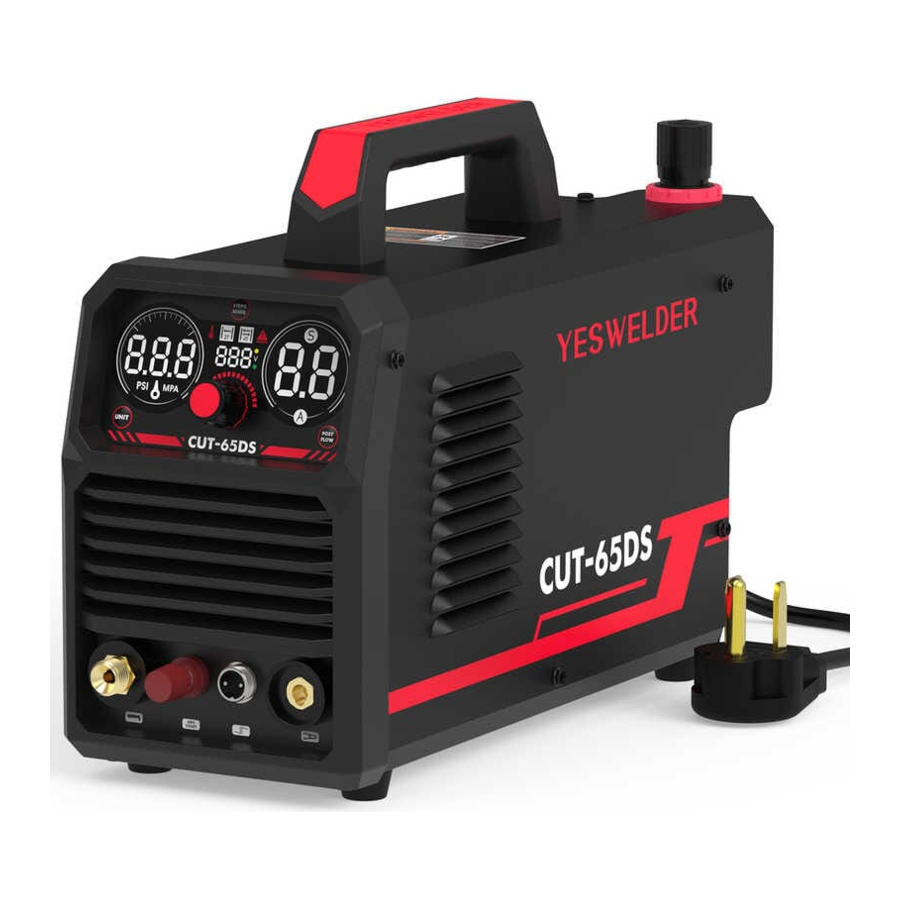
YesWelder CUT-65DS is a non-high frequency start machine. Blow-back type start involves a rearward movement of the electrode within the torch head when forced by the air pressure When air pressure is applied the movement of the electrode off its seated position against the inner surface of the circuit grounded nozzle creates a spark, energizing the plasma stream. With this machine's start type and pilot arc design, you are able to cut on any metal surface without having to contact to strike an arc which is ideal for cutting items like expanded metal or uneven surfaces. This Cutting machine has a wide range of uses which is suitable for cutting: stainless steel, alloy steel, mild steel, copper and other color metal materials
PACKAGING DETAILS

- Welder
- Ground Clamp&Cable(10ft)
- Air Compressor Filter
- Adapter
- Gas Hose
- IPT40 Plasma Cutting Torch
TECHNICAL SPECIFICATIONS
| General Technical Parameters | ||
| CUT-65DS | ||
| Rated Input Power Supply | Single-phase ACI IOV 50Hz | Single-phase AC220V 50Hz |
| Rated Input Capacity (KVA) | 5 | 8,4 |
| Power Factor | 07 | 07 |
| Rated Output(A/V) | 45/98 | 65/106 |
| Rated Duty Cycle(%) | 60% | 60% |
| No-load Voltage(V) | 265 | 265 |
| Output current range (A) | 20-45 | 20-65 |
| Arc Ignition Mode | Non HF | |
| Post-flow Time (S) | 5-20 | |
| Gas Pressure Range (Mpa) | 0.3-0.45 | 0.4-0.6 |
| Insulation Grade | F | |
| Cooling Mode | Air Cooling | |
| Enclosure Ingress Protection | IP21S | |
| Efficiency (%) | 85% | |

POWER SOURCE DIMENSIONS AND WEIGHT
9kg(19.8lbs)
408X160X290mm (16X6.3X11in)

INSTALLATION, SIZE, AMC WEIGHT of CUTTING TORCH

INSTALLATION
Read entire Installation Section before installing the CUT-65DS.
SAFETY PRECAUTIONS

ELECTRIC SHOCK CAN KILL.

- Only qualified personnel should install this machine
- Turn the input power OFF at the disconnect switch or fuse box and discharge input capacitors before working inside the equipment
- DO not touch electrically hot parts
- Tum the CUT-55DS PRO Power Switch OFF when connecting power cord to input power.
SELECT PROPER LOCATION
Place the CUT-55DS PRO where clean cool air can freely circulate in and out the side louvers Dirt, dust or any foreign material that can be drawn into the machine should be kept at a minimum Failure to observe these precautions can result in excessive operating temperatures and nuisance shutdown of the machine.
A source of clean, dry air must be supplied to the CUT-55DS PRO. Oil in the air is a severe problem and must be avoided. The sup ply pressure must be between 50.7 and 87 psi. Failure to observe these precautions could result in excessive operating temperatures or damage to the torch
STACKING
The CUT-55DS PRO cannot be stacked.
TILTING
The CUT-55DS PRO must be placed on a stable, level surface so it will not topple over.
GAS INPUT CONNECTIONS (External Air supply)
Supply the CUT-65DS with clean compressed air
- Supply pressure must be between 0.3 and 0.6 Mpa.
(At a voltage of 110V, Recommended supply pressure is between 0.3 and 0.45 Mpa; At a voltage of 220V, Recommended supply pressure is between 0.4 and 0.6 Mpa)
INSTALLATION FOR AIR PRESSURE COMPRESSOR FILTER REGULATOR
NOTE:

- Regularly drain the water inside the pressure-reducing valve
- When the water level reaches two-thirds of the water filter cup, water must be discharged; otherwise, the cut quality will be affected
- Oil in the air supply to the CUT-65DS can cause severe problems. Use only a clean air supply
OUTPUT CONNECTIONS
CONNECTING TORCH AND WORK LEAD

CONNECTING WORK CLAMP
The work clamp must be securely connected to the workpiece. If the work piece is painted or extremely dirty it may be necessary to expose the bare metal in order to make a good electrical connection

INPUT CONNECTION
The CUT-65DS is rated for 1 IOVAC and 220VAC input voltage Before installing the machine, check that input supply voltage, phase, and frequency are the same as the machine's voltage, phase, and frequency as specified on the machine's rating plate. The CUT-65DS automatically senses and adjusts to work with the input voltage listed on the rating plate when connected to the cor responding plug
- The CUT-65DS should be connected only by a qualified electrician. Installation should be made in accordance with local codes.
OPERATION
SAFETY PRECAUTIONS
CYLINDER MAY EXPLODE IF DAMAGED.
 | ELECTRIC SHOCK CAN KILL.
|
 | FUMES AND GASES can be dangerous.
|
 | WELDING, CUTTING and GOUGING SPARKS can cause fire or explosion
|
 | ARC RAYS can burn.
|
 | PLASMA ARC can injure
|
Observe additional Safety Guidelines detailed in the beginning of this manual.
PANEL FUNCTIONS of CUT-65DS

- Gas-electric connector
(Connect the cutting torch) - Pilot arc
(connect the pilot wire of torch) - Torch Switch
(connect the control of cutting torch) - Earth Clamp Connector
- Air Compressor Filter
- Power Cable
- Power Switch
- Rating Plate
- Cooling Fan
- Air Pressure Adjustment Button
(rotate towards "+" to augment pressure; swivel towards "-" to diminish pressure)

- UNIT
Press this button to change the gas pressure display values from PSI to MPA or from MPA to PSI. - GAS PRESSURE DISPLAY
This display shows the gas pressure in PSI or MPA Unit. When certain system faults occur, this display shows a fault code See error codes and solutions. - PSI
Gas pressure unit - MPI
Gas pressure unit - CENTER KNOB
Adjustment of the electric current value and POST Flow time value by turning the center knob left or right - 110V/220V
This display shows the input voltage (110/220VAC) - POWER ON LED (Green)
When illuminated, this LED indicates that the power switch is set to ON and the system is ready to cut - LED (Yellow)
Yellow light on: the input voltage is over or below the reasonable range. The cutting effect will be worse. Need to check whether the input voltage is normal. ![]()
When the internal components of the cutter are damaged, the WARNING indicator lights up- 2T
Display the current cutting mode is 2T. - 4T
Display the current cutting mode is 4T. - THERMOMETER ICON
When the operating temperature of the machine is too high, the gas pressure display shows E-3. Thermal protection (the thermometer symbol lights up). - STEPS MODE
Press this button to toggle between 2T and 4T. - POST FLOW
Press this button to enter the set Post flow time mode. - A
Setting output current mode indicator, the indicator light is on when the machine is in setting current mode - CURRENT VALUE AND POST FLOW TIME DISPLAY
This display shows the set output current or set post flow time. - S
Post flow time setting mode indicator, the indicator lights up when the machine is in post flow time setting mode. (Post flow-After you complete a cut and release the torch trigger, air continues to flow from the torch in order to cool the consumables.)
- After power on, the digital screen lights up and the right display panel will display the preset output current. The middle display panel automatically recognizes and displays the input voltage of 220V/110V (if the input voltage is within an acceptable range, the green light will light up; otherwise, the yellow light will light up, indicating the need to check for undervoltage).


- Air Pressure Display: The display will show the air pressure immediately after connection to the pneumatic system and startup; in case of startup without air supply, the screen will show "E-5".

- 2T/4T: Upon initiation, the primary screen will exhibit the 2T cutting mode

- Pressure Value Configuration Interface: During the process of setting the pressure values, the numerical screen will provide a real-time display of the adjusted barometric readings

- Steps Are As Follows: Start the gas flow; Lift the air pressure adjustment button upward; Adjust the gas pressure to the desired value by rotating the knob (rotate to "+" direction to increase gas pressure; rotate to "-" direction reduce gas pressure); Press down the pressure control knob to get the knoblocked.

- Pneumatic Pressure Unit Conversion: Accommodates both PSI and MPl units, with PSI as the default measurement The unit may be altered by engaging the UNIT button, which prompts the display to indicate the selected denomination during the transition.


- Output Current Configuration Interface: During the setting of the current value, the numerical screen will provide a real-time display of the adjusted amperage

- Operational Procedure: Preset the cutting current based on the workpiece's thickness by utilizing the central knob for adjustment. Rotate it counterclockwise to decrease the current or clockwise to increase it. The red light bar above will correspondingly flect the current's magnitude in synchrony

- Post-flow Time Adjustment Interface: During the configuration of post-flow time, the digital display will dynamically reflect the changes to the duration.

- Post-flow Duration Configuration: Depress the POST FLOW button to transition into post-flow timing mode (indicated by the illumination of the "S" light). Adjust the duration using the central dial; turn left to decrease and right to increase the time value. The light bar above will visually sync to reflect the magnitude of the duration (default post-flow time: 5 seconds, with an adjustable span from 5 to 2() seconds). After a lapse of 5 seconds upon configuration, the system will revert to the current setting mode automatically, displaying the preset current as the "S" indicator light extinguishes and the "A" light activates. Alternatively, one may press the button directly to switch back to the current setting mode
- (NOTE: The cutter will remain in Output Current Configuration Interface when POST FLOW is not pressed to toggle the setting The character A is displayed at the bottom of the screen (representing that it is now in the Output Current Configuration Interface) and the character S is displayed at the top of the screen (representing that it is now in the post-flow Time Adjustment Interface))

- Thermometer symbol: When the operating temperature of the machine is too high, it lights up, the screen displays E-3, and the machine stops working at the same time


- Warning Indicator Light: When the internal components of the cutting machine are damaged, the warning indicator light will light up and the air pressure display screen will display E-1


CUTTING PROCESS
SET PARAMETERS AND ADJUST OUTPUT CURRENT (AMPERAGE)
- Adjust the air pressure
- Press the UNIT button to change the gas pressure display unit
- Adjust the air compressor's output air flow and pressure and make it is adequate to machine, open the valve of the air compressor
- Turn the Center Knob to adjust the amperage. Make sure cutting current is adequate to machine specifications according to thickness of cutting piece
- Press the POST FLOW button to select post flow. And turn the Center Knob to adjust the post flow time.
- Press the STEPS MODE button to select 2T or 4T mode.
CHECK CUT SETTINGS AND INDICATOR LEDS
Before you start to cut, make sure:
- The green power ON LED on the front of the power supply is illuminated
- The voltage display corresponds to the actual input voltage
- The output current (amperage) displayed on the front panel is correct, and the "A" LED is illuminated
- The gas pressure displayed on the front panel is correct.
- None of the fault LEDs or CODE are illuminated
If any of the fault LEDs or CODE illuminate, or if the power ON LED illuminate, this indicates a fault. Correct the fault condition be fore continuing. See error codes and solutions.
READY TO CUT
INSTANT-ON TORCHES PLASMA ARC CAN CAUSE INJURY AND BURNS
The plasma arc ignites immediately when you pull the torch trigger. Make sure the power is OFF before changing consumables Trigger on the torch to activate the torch and let air go through The pilot arc will come on and remain on for 5 seconds during which the cutting tip must come into contact with the workpiece
- If the cutting tip does not come into contact with the workpiece within 5 seconds of the pilot arc start, the arc automatically stops (the post flow air continues to run, cooling the plasma torch)
NOTES FOR CUTTING OPERATION
 |
|
 |
|
 |
|
 |
|
 |
|
 |
|
 |
|
 |
|
The Workpiece is Not Cut Fully. This May be Caused by:
- The cutting current is too low.
- The cutting speed is too high.
- The electrode and nozzle of the torch are bumed
- The workpiece is too thick
Molten Slag Drops From The Bottom of Workpiece. This May be Caused by:
- The cutting speed is too low
- The electrode and nozzle of the torch are burned
- The cutting current is too high
CUTTING PARAMETERS TABLE
Select proper current according to the cutting parameters table, workpiece material, cutting thickness and cutting speed, etc (The figure in the below table is an approximation.)
Cutting Speed (m/min) When Cutting Current is 65A
 When Cutting Current is 65A")
REPLACEMENT OF ELECTRODE AND NOZZLE
When the phenomena below occur, the electrode and nozzle should be replaced Othervvise, there will be strong arc in the nozzle, which will break down the electrode and the nozzle, or even burn the torch. Nozzles of different models are different, so ensure the nozzle is of the same model when replacing it.
- Electrode wear > 1 5mm
- Distortion of the nozzle
- Cutting speed declining, arc with green flame
- Difficult in arc ignition
- Irregular cut
MAINTENANCE
ELECTRIC SHOCK CAN KILL.
- Have an electrician install and service this equipment.
- Turn the input power Off at the fuse box before working on equipment
- DO not touch electrically hot parts
ROUTINE MAINTENANCE
- Keep the cutting or gouging area and the area around the machine clean and free of combustible materials No debris should be allowed to collect which could obstruct air flow to the machine
- Every 6 months or so, the machine should be cleaned with a low pressure airstream. Keeping the machine clean will result in cooler operation and higher reliability Be sure to clean these areas:
- Printed circuit boards and heat sinks
- Power switch
- When using a low pressure air stream, wear appropriate eye protection.
- Examine the sheet metal case for dents or break-age. Repair the case as required Keep the case in good condition to insure that high voltage parts are protected and correct spacings are maintained. All external sheet metal screws must be in place to insure case strength and electrical ground continuity
- Every 6 months or so, the machine should be cleaned with a low pressure airstream. Keeping the machine clean will result in cooler operation and higher reliability Be sure to clean these areas:
- Regularly clean the compressor air inlet filter
ELECTRIC SHOCK CAN KILL.

- Turn off machine at the disconnect switch on the rear of the machine before tightening, cleaning or replacing consumables
Change consumables as required.
Thermal Detection Devices protect the machine from excessive operating temperatures. Excessive temperatures may be caused by a lack of cooling air Or operating the machine beyond the duty cycle and Output rating If excessive operating temperatures should occur, the yellow thermal LED will light and the Detection Devices will prevent output voltage or cur-rent. These Detection Devices are self-resetting once the machine cools sufficiently. If the thermostat shutdown was caused by excessive output or duty cycle and the fan is operating normally, the Power Switch may be left on and the reset should occur within a 15 minute period. If the fan is not turning or the air intake louvers were obstructed, then the power must be switched off and the fan problem or air obstruction must be correct.

MAINTAIN TORCH COMPONENTS BEFORE EVERY USE AND AFTER EVERY HOUR of OPERATION.
Disconnect power cord and make sure Torch is completely cool, then:
- Disassemble Torch.
- Inspect the Cutting Tip. Replace if interior is damaged, or if opening is enlarged or gouged. Clean inside as needed with steel wool, (remove any pieces of steel wool afterwards)
- Inspect the Electrode. Replace if pitted 1/16" or more or if misshapen.
IMMEDIATELY REPLACE WORN COMPONENTS.
- Make sure all other internal torch components are undamaged, clean, and free of debris
- NOTICE: Assemble Electrode just snug using the included wrench, but do not overtighten
- Insert the Swirl Ring and Cutting Tip into the torch.
- Assemble the Retaining Cup tightly.
DO NOT USE WITH WORN COMPONENTS. USING WORN COMPONENTS WILL VOID THE WARRANTY AND DAMAGE THE PLASMA CUTTER.
TROUBLESHOOTING
The abnormity indicator on the front panel would illuminate in case of any failures inside the cutting machine.
| Malfunction Phenomena | Cause and Solution |
| The yellow light next to the input voltage is on (yellow light indicates undervoltage) | Employ a multimeter to gauge the DC voltage input. Should the input voltage be deemed appropriate, proceed with pow ering down and restarting the device to ascertain its operational status. |
| When the machine's digital display reads "E- 5" | Inspect whether the external pressure reduction valve is open and verify the internal solenoid valve's functionality |
| The absence of arc maintenance and ignition in the machine | Utilize the multimeter set to DC voltage to measure the noload voltage of the device, thereby assessing the arc maintenance relays performance. This relay should engage upon startup and disengage upon shutdown. Ensure the in put voltage falls within the acceptable range and note that the solenoid valve operates optimally at an air pressure of 0.8 MPA; pressures exceeding this threshold may result in malfunction. |
The machine fails to power up | Confirm the normalcy of the input voltage, the functionality of the power switch, and scrutinize the machine's internal wiring for any signs of loosening |
| The machine maintains an arc and ignites but cannot cut effectively | Using a clamp meter set to the DC current range, clamp it onto the ground clamp and monitor the current. An absence of current might suggest an internal circuit issue or a failure of the reed switch tasked with current detection. Deformations in the bracket above the nozzle or excessive distance between the cutting tip and the workpiece can also prevent proper cutting |
ERROR CODES AND SOLUTIONS
 | When the internal components of the cutting machine are damaged, the warning indicator light will light up and the air pressure display screen will display E-1 |
 | When the operating temperature of the IGBT is too high, the gas pressure display: E-3. |
 | When turned on without air pressure, the gas pressure display E-5 |
www.yeswelder.com
Toll Free (855) 937-4567
Documents / Resources
References

Download manual
Here you can download full pdf version of manual, it may contain additional safety instructions, warranty information, FCC rules, etc.
Advertisement


Need help?
Do you have a question about the CUT-65DS PRO and is the answer not in the manual?
Questions and answers