YESWELDER MIG-250 PRO - Professional Welder Manual
- Operator's manual (36 pages)
Advertisement
- 1 CONTENTS
- 2 SPECIFICATIONS
- 3 DUTY CYCLE
- 4 SAFETY INFORMATION
- 5 CONNECTING THE WELDER TO A POWER SOURCE
- 6 CONTROL AND DISPLAY PANEL
- 7 MIG WELDING SET-UP AND OPERATION
- 8 MIG WELDING OPERATION
- 9 STICK WELDING SET-UP AND OPERATION
- 10 Lift TIG WELDING SET-UP AND OPERATION
- 11 Lift TIG WELDING
- 12 OVERLOAD PROTECTION
- 13 TYPES OF WELD JOINTS
- 14 STICK WELD TROUBLESHOOTING
- 15 MIG WELD TROUBLESHOOTING
- 16 TIG WELDING TROUBLESHOOTING
- 17 CODE OF OPERATION AND ERROR
- 18 Documents / Resources
CONTENTS

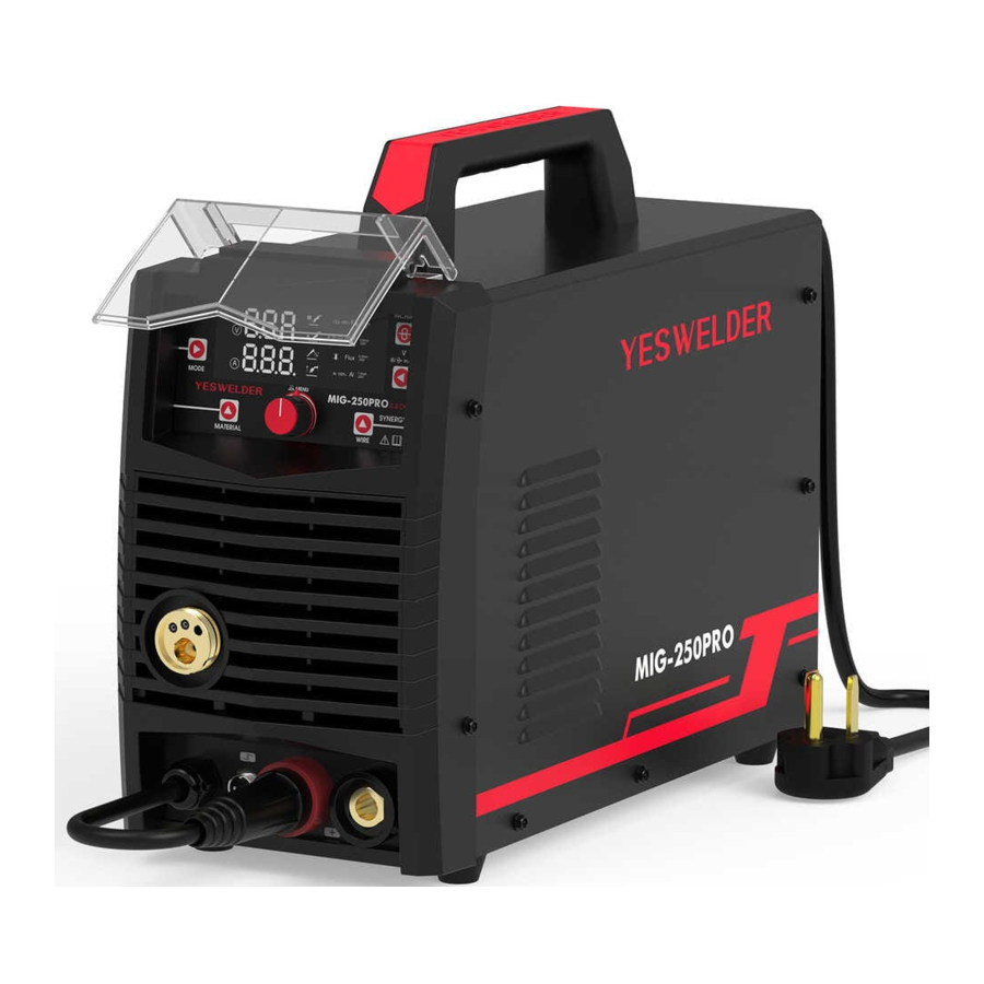
- MIG-250 PRO Multi-Process Welder
- MIG Torch with 10'(3m) Cable (.030"/0.8mm contact tip installed)
- Graphene liner
- Electrode Holder with 10'(3m) Cable
- Shielding Gas Hose (EURO style or US style)
- Ground Clamp with 10'(3m) Cable
SPECIFICATIONS
| Input Power | Frequency | Input Current | No-Load Voltage | MIG Welding Current | Lift TIG Welding Current | Stick Welding Current | Rated Duty Cycle | Insulation Grade | Cooling Type |
| VAC | Hz | Amps | V | A | A | A | % | IP | - |
| 220 | 50/60 | I1 max=34A I1 ett=26.3A | 65 | 30-250 | 20-250 | 20-225 | 60% | IP21S | Fan Cooling |
MIG WELDING WIRE
| Solid Wire | Flux Core | SS wire | AL 5356/4043 | |
| Wire Type and Diameter | .023"/.030"/.035" (0.6/0.8/0.9mm) | .030"/.035" (0.8/0.9mm) | .023"/.030"/.035" (0.6/0.8/0.9mm) | .035"/.045" (0.9/1.2mm) |
ARC WELDING RODS
| Type | E7018 |
| Diameter | 1/16", 3/32", 1/8" |
| Polarity | DCEN |
DUTY CYCLE
The rated Duty cycle refers to the amount of welding that can be done within an amount of time. The YESWELDER MIG-250 PRO has a duty cycle of 600/0at 250 Amps for 220 Volts. It is easiest to look at your welding time in blocks of 10 Minutes and the Duty Cycle being a percentage of that 10 Minutes. If welding at 250 Amps with a 60% Duty Cycle, within a 10 Minute block of time you can weld for 6 Minutes with 4 Minutes of cooling for the Welder.
SAFETY INFORMATION
Welding can be dangerous to you and other persons in the work area. Read and understand this instruction manual before using your YESWELDER welding machine. Injury or death can occur if safe welding practices are not followed.
Safety information is set forth below and throughout this manual.
To learn more about welding safety, read OSHA Title 29 CFR 1910, available at www.osha.gov; ANSI Z49.1, "Safety in Welding, Cutting and Allied Processes", available at www.aws.org; and the consumable manufacturer's Safety Data Sheet.
The following explanations are displayed in this manual, on the labeling, and on all other information provided with this product:

indicates a hazardous situation which, if not avoided, will result in death or serious injury.

indicates a hazardous situation which, if not avoided, could result in death or serious injury.

used with the safety alert symbol, indicates a hazardous situation which, if not avoided, could result in minor or moderate injury.
 NOTICE: is used to address practices not related to personal injury.
READ INSTRUCTIONS
Thoroughly read and understand this manual before using. Save for future reference.

ELECTRIC SHOCK CAN CAUSE INJURY OR DEATH!
- Improper use of an electric Welder can cause electric shock, injury and death! Read all precautions described in the Welder Manual to reduce the possibility of electric shock.
- Disconnect Welder from power supply before assembly, disassembly or maintenance of the torch, contact tip and when installing or removing nozzles.
- Always wear dry, protective clothing and leather welding gloves and insulated foot wear. Use suitable clothing made from durable flame-resistant material to protect your skin.
- Always operate the Welder in a clean, dry, well ventilated area. Do not operate the Welder in humid, wet, rainy or poorly ventilated areas.
- The electrode and work (or ground) circuits are electrically "hot' when the Welder is on. Do not allow these "hot" parts to come in contact with your bare skin or wet clothing.
- Separate yourself from the welding circuit by using insulating mats to prevent contact from the work surface.
- Be sure that the work piece is properly supported and grounded prior to beginning an electric welding operation
- Always attach the Ground Clamp to the piece to be welded and as close to the weld area as possible. This will give the least resistance and best weld.
WELDING SPARKS CAN CAUSE FIRE OR EXPLOSION!
- Electric welding produces sparks which can be discharged considerable distances at high velocity igniting flammable or exploding vapors and materials.
- DO NOT operate electric arc Welder in areas where flammable or explosive vapors are present.
- DO NOT use near combustible surfaces. Remove all flammable items from the work area where welding sparks can reach (min. of 35 feet)
- Always keep a fire extinguisher nearby while welding.
- Use welding blankets to protect painted and or flammable surfaces; rubber weatherstripping, dash boards, engines, etc
- Ensure power supply has properly rated wiring to handle power usage.
ELECTROMAGNETIC FIELDS CAN BE A HEALTH HAZARD!
- The electromagnetic field that is generated during arc welding may interfere with various electrical and electronic devices such as cardiac pacemakers. Anyone using such devices should consult with their physician prior to performing any electric welding operations
- Exposure to electromagnetic fields while welding may have other health effects which are not known.
ARC RAYS CAN INJURE EYES AND BURN!
- Arc rays produce intense ultraviolet radiation which can burn exposed skin and cause eye damage. Use a shield with the proper filter (a minimum of #11) to protect your eyes from sparks and the rays of the arc when welding or when observing open arc welding (see ANSI Z49.1 and Z87.1 for safety standards)
- Use suitable clothing made from durable flame-resistant material to protect your skin.
- If other persons or pets are in the area of welding, use welding screens to protect bystanders from sparks and arc rays.
FUMES AND WELDING GASES CAN BE A HEALTH HAZARD!
- Fumes and gasses released during welding are hazardous. Do not breathe fumes that are produced by the welding operation. Wear an OSHA-approved respirator when welding
- Always work in a properly ventilated area
- Never weld coated materials including but not limited to: cadmium plated, galvanized, lead based paints
HOT METAL AND TOOLS WILL BURN!!
- Electric welding heats metal and tools to temperatures that will cause severe burns!
- Use protective, heat resistant gloves and clothing when using YESWELDER or any other welding equipment. Never touch welded work surface, torch tip or nozzle until they have completely cooled
FLYING METAL CHIPS CAN CAUSE INJURY!
- Grinding and sanding will eject metal chips, dust, debris and sparks at high velocity. To prevent eye injury wear approved safety glasses.
- Wear an OSHA-approved respirator when grinding or sanding
- Read all manuals included with specific grinders, sanders or other power tools used before and after the welding process. Be aware of all power tool safety warnings.
INADEQUATE WIRING CAN CAUSE FIRE AND INJURY!
- Verify that the facility power source has properly rated wiring to handle power requirements of this Welder.
CONNECTING THE WELDER TO A POWER SOURCE
The YESWELDER MIG-250 PRO Welder requires a dedicated AC single phase 220V, 50/60HZ grounded outlet protected by a (50 Amp @ 220V) circuit breaker.
CONTROL AND DISPLAY PANEL

FIG.1
The YESWELDER MIG-250 PRO Front Panel is equipped with 5 Function Controls, One Digital Display and 5 select buttons, One Value Knob.
They are as follows:
FUNCTION CONTROLS
A - 100% CO2 or Ar 75% CO2 25% (Ar CO2 20%) Solid Wire Carbon Steel Welding
S MIG -Synergic Carbon Steel, (Recommend.030"/.035")
Set the MODE button on front panel to S MIG (s  ), (user set the welding ampere, the voltage and wire feed speed will be auto fitted by welder data program (Recommend for skilled and beginner welders)
Set the MATERIAL button on front panel to CO2 100%Fe or Ar 75% CO2 25% Fe (Ar 80% CO2 20% also works on this program).
Set the WIRE button on front panel to.023", .030" or.035" refer to the wire used in machine. Make sure the V type roller used and Steel liner of torch used for carbon steel welding.
Adjust MENU knob, set the welding ampere according to welding chart.
Press the MENU button enter specifications of MIG, 2T/4T (2steps or 4steps of welding), set the value of IND (inductance), HS (Hot start) and BBT (Burn Back Time). (Recommend to use Default Value)
Remove the tips, press and hold INCHING button, till the wire come out of torch neck.
Fasten the tips according to correct wire diameter (.023" 0.6mm/.030" 0.8mm/.035" 0.9mm) and Nozzle.
Set the V button on front panel, the voltage can micro change from -5 to +5 (each 1 value=0.3V, Reduce 1.5V~Add 1.5V), Wire feed speed can not be adjustable
B - Ar 75% CO2 25% (Ar CO2 20%) Solid Wire Stainless Steel Welding
S MIG-Synergic Stainless Steel, (Recommend.030"/.035")
Set the MODE button on front panel to S MIG (s ), (user set the welding ampere, the voltage and wire feed speed will be auto fitted by welder data program (Recommend for skilled and beginner welders)
Set the MATERIAL button on front panel to CO2 100% Fe or Ar 75% CO2 25% Ss (Ar 80% CO2 20% also works on this program).
Set the WIRE button on front panel to.023", .030" or.035" refer to the wire used in machine. Make sure the V type roller used and Steel liner of torch used for Stainless steel welding
Adjust MENU knob, set the welding ampere according to welding chart.
Press the MENU button enter specifications of MIG, 2T/4T (2steps or 4steps of welding), set the value of IND (inductance), HS (Hot start) and BBT (Burn Back Time). (Recommend to use Default Value)
Remove the tips, press and hold INCHING button, till the wire come out of torch neck.
Fasten the tips according to correct wire diameter (.023" 0.6mm/.030" 0.8mm/.035" 0.9mm) and Nozzle.
Set the V button on front panel, the voltage can micro change from -5 to +5 (each 1 value=0.3V, Reduce 1.5V~Add 1.5V), Wire feed speed can not be adjustable.
C - Gasless Flux Core Wire Carbon Steel Welding
S MIG-Synergic Carbon Steel, Gasless.035"
Set the MODE button on front panel to S MIG ( s ), (user set the welding ampere, the voltage and wire feed speed will be auto fitted by welder data program (Recommend for skilled and beginner welders)
Set the MATERIAL button on front panel to  Flux
Flux
Note: .035" wire is only available on Gasless MIG welding.
Make sure the type W-knurled roller used and Steel liner of torch used for Carbon steel welding.
Adjust MENU knob, set the welding ampere according to welding chart.
Press the MENU button enter specifications of MIG, 2T/4T (2steps or 4steps of welding) set the value of IND (inductance), HS (Hot start) and BBT (Burn Back Time). (Recommend to use Default Value)
Remove the tips, press and hold INCHING button, till the wire come out of torch neck.
Fasten the tips according to correct wire diameter (.023" 0.6mm/.030" 0.8mm/.035" 0.9mm) and Nozzle.
Set the V button on front panel, the voltage can micro change from -5 to +5 (each 1 value=0.3V, Reduce 1.5V~Add 1.5V), Wire feed speed can not be adjustable.
D - 100% Argon Gas Aluminum Steel Welding with U type Roller and Graphene Liner.
S MIG-Synergic Aluminum steel, 100% Argon Gas.035"/045" Set the MODE button on front panel to S MIG (s ), (user set the welding ampere, the voltage and wire feed speed will be auto fitted by welder data program (Recommend for skilled and beginner welders).
Set the MATERIAL button on front panel to
Set the WIRE button on front panel to.035" or.045" refer to the wire used in machine. Make sure the U type roller used and Graphene liner of torch used for Aluminum steel welding.
Adjust MENU knob, set the welding ampere according to welding chart.
Press the MENU button enter specifications of MIG, 2T/4T (2steps or 4steps of welding).
Set the value of IND (inductance), HS (Hot start) and BBT (Burn Back Time). (Recommend to use Default Value).
Remove the tips, press and hold INCHING button, till the wire come out of torch neck Fasten the Marked 'A' (Aluminum) tips according to correct wire diameter (.035" 0.9mm/.045" 1.2mm) and Nozzle.
Set the V button on front panel, the voltage can micro change from -5 to +5 (each 1 value=0.3V, Reduce 1.5V~Add 1.5V), Wire feed speed can not be adjustable.
E - M100% Argon Gas Aluminum Steel Welding with Spool Gun
M Manual MIG: Aluminum steel, 100% Argon Gas.035"/.045"
Note: Spool Gun is not included, need to purchase separately.
Set the MODE button on front panel to M MIG (M  ), Switch to Spoon Gun Mode (
 ) int he wire feeding part and Connected the torch and the control switch.
Set the MATERIAL button on front panel to
Set the WIRE button on front panel to.035" or.045"-Aluminum Steel refer to the wire used in machine.
Adjust MENU knob, set the voltage and wire feed speed separately, amperage will be auto adjusted when changing the wire speed.
F - Manual MIG Welding (Free Setting on Voltage and Wire feed Speed (Welding Amp will automatic fitting with Wire Feed Speed)
Note: Gasless Flux MIG is only available for.035" Wire Diameter, can weld with no Gas.
M MIG-Manual setting Voltage/Wire Feed Speed on Carbon Steel/Stainless Steel (Recommend.030"/.035") And Aluminum Steel (.035"/.045") (Available for Professional Welder Only)
Set the MODE button on front panel to M MIG (M ), (user set the welding ampere, the voltage and wire feed speed separately
Set the MATERIAL button on front panel to 
Set the WIRE button on front panel to.023", .030" or.035"-Carbon Or Stainless Steel; 035" or.045"-Aluminum Steel refer to the wire used in machine.
Make sure the V type roller used and Steel liner of torch used for Carbon or Stainless Steel Welding.
The U type roller used and Graphene liner of torch used for Aluminum steel welding.
Adjust MENU knob, set the welding ampere according to welding chart.
Set the V button on front panel, change the value of Voltage (12.5-30V) and Wire feed speed (2-15 m/Min).
Press the MENU button enter specifications of MIG, 2T/4T (2steps or 4steps of welding) set the value of IND (inductance), HS (Hot start) and BBT (Burn Back Time). (Recommend to use Default Value)
Remove the tips, press and hold INCHING button, till the wire come out of torch neck.
Fasten the tips according to correct wire diameter (.023" 0.6mm/.030" 0.8mm/.035" 0.9mm) and Nozzle. (Carbon Steel and Stainless Steel Weld)
Fasten the Marked 'A' (Aluminum) tips according to correct wire diameter (.035" 0.9mm/.045" 1.2mm) and Nozzle. (Aluminum Steel Weld)
G - Stick Welding
Set the MODE button on front panel to  , Adjust MENU knob, set the welding ampere according to welding chart.
Press the MENU button enter specifications of MMA, DIG (Arc Force Current, easier for arc starting on thick work piece), HS (Hot Start Time-easier for start arc on cellulose electrode), VRD ON/OFF (Voltage Reduce Function for avoid leakage of voltage in humid environment), ANT ON/OFF (Anti-stick function on/off)
H - Lift TIG Welding
Set the MODE button on front panel to  , Setup the Lift tig torch (Not included)
MIG WELDING SET-UP AND OPERATION
SET UP FOR MIG WELDING
Installing the MIG Welding Gun
Open the side door of the Welder and loosen the Torch Tensioner Wing Screw located on the side of the brass, hex shaped member of the Drive Motor Assembly (FIG. 2)

Plug the Brass Body End of the Welding Gun line into the designated socket (FIG. 3)


The Brass Body End must be fully seated against the base of the drive assembly socket or gas may either leak or not be able to pass through the connections to the end of the Welding Gun (FIG. 4).

Tighten the Torch Tensioner Wing Screw finger tight (FIG. 3). Connect the Male Metal Plug to the Female Cannon Plug Connection on the front of the Welder (FIG. 5).
 FLUX(DCEN)
CO2 100% (DCEP)
Ar/CO2 Mix(DCEP)
AI(DCEP)
Set the MODE button located on the Front Panel to the MIG (FIux, CO2 100% or Ar/CO2 Mix/AL Position (FIG. 1).
Install Torch and Liner for Aluminum Welding
Remove the spring on the plastic parts of wire feeder (FIG. 5-1),

keep it in safe place, need to install it back when we use ss or carbon steel weld. Remove the holding ring on steel liner of wire feeder, press steel liner (FIG. 5-2, 5-3)

and let it move out of the torch sockets on front panel, keep it in safe place, need install it back when we weld with ss and carbon steel. use torch kid remove the tip (FIG. 5-4)

on the torch, remove the screw (FIG. 5-5) on torch liner back

Install A Spool Gun for Aluminum Welding
Remove the regular MIG torch and connect the torch and the 2-pin switch. Locate the Ground Clamp with Cable and connect the plug to the Negative Connector (—) on the Welder. (DCEP) Check the wire size on the torch and install the aluminum wire. Switch the I-O button for spool gun.

Pull the steel liner (FIG. 5-6)

out of the torch, keep it in safe place, need install it back when we weld with ss or carbon steel. Install the Graphene liner (FIG. 5-7)

into torch (make sure the liner into torch with correct direction, keep the steel part toward the torch head), insert the Graphene liner to the torch socket on front panel (FIG. 5-8),

come cross liner hole of torch till to the edge of roller (FIG. 5-9). (aluminum material wire is soft, so we need keep using Graphene liner used in weld and change U type roller for aluminum welding)

INSTALLING THE GROUND CABLE AND CLAMP
Locate the Ground Clamp with Cable and connect the plug on the cable end to the Negative Connector (—) on the welder. (DCEP @ CO2 100% or Ar/CO2 Mix/Aluminum) to the Positive Connector (+) on the Welder. (DCEN @ Flux)
Align the key of the brass ferrule with the notch of the receptacle at the 12:00 position (FIG. 6),

insert the plug and twist Clockwise 1/2 turn until it is tight (FIG. 7).

INSTALLING THE SHIELDING GAS SUPPLY
BUILDUP OF GAS CAN A WARNING INJURE OR KILL!
- Shut off shielding gas supply when not in use.
- Always ventilate confined spaces or use approved air-supplied respirator.
- Always turn your face away from valve outlet when opening cylinder valve
CYLINDERS CAN EXPLODE A WARNING IF DAMAGED!
Shielding gas cylinders contain gas under high pressure. If damaged, a cylinder can explode. As gas cylinders are a normal component of the welding process, use extra care to handle them carefully.
- Protect compressed gas cylinders from excessive heat, mechanical shocks, physical damage, slag, open flames, sparks and arcs. Keep away from any welding or other electrical circuits.
- Install cylinders in an upright position by securing to a specifically support to prevent falling or tipping over.
- Never weld on a pressurized cylinder or explosion will occur.
- Use only correct shielding gas cylinders, regulators, hoses and fittings designed for the specific application; maintain them and all related components in good condition.
- Keep protective cap in place over valve except when cylinder is in use.
- Use proper equipment, procedures and have adequate help when moving or lifting cylinders.
A Shielding Gas Bottle is NOT INCLUDED with your YESWELDER MIG-250 PRO but is necessary to weld using Solid Wire. It can be bought at most local Welding Supply Stores. YESWELDER recommends the use of 80% Argon / 20%CO2 or 75% Argon / 25% CO2 for shielding gas when MIG welding Steel.
- Place the YESWELDER MIG-250 PRO in its dedicated area or on a welding cart
- Secure your Shielding Gas Bottle to a stationary object or mount to your welding cart if it is equipped to hold one so that the cylinder cannot fall over.
- Remove the cap from the Shielding Gas Bottle.
- Install the Regulator Knob on the Shielding Gas Regulator (FIG. 8)

- Insert the large brass male fitting on the Shielding
- Gas Regulator into the female fitting on the Shielding Gas Bottle (FIG. 9).


NOTICE: Do not use White Thread Sealing Tape on this connection as it is an inert gas fitting and does not require it. If you have a leak, check for burrs or dirt in the threads.
- Tighten the fitting with a wrench until snug, do not over tighten.
- Connect either end of the Gas Line included with your YESWELDER MIG-250 PRO to the fitting on the regulator and wrench tighten until snug (FIG.9)
- Connect the other end of the gas line to the fitting on the rear of the YESWELDER MIG-250 PRO
- and wrench tighten until snug (FIG. 10).

Check the gas line for leaks by slowly opening the valve on the gas bottle. When welding the valve on the bottle should always be fully open.

POSITIONING THE DRIVE ROLLER
The YESWELDER MIG-250 PRO Wire Drive Roller has twin grooves to accommodate both 0.030"/0.035" (0.8mm/0.9mm) wire.
The MIG-250 PRO Drive Roller is factory set and up ready to use 0.030"/0.035" (0.8mm/0.9mm) wire
In this position, the wider, 0.030"/0.035" (0.8mm/0.9mm) grove is inboard, under the wire while the 0.8/0.9 marking is visible on the outward face of the Drive Roller (FIG. 11).

0.030" (0.8mm) or 0.035" (0.9mm) wire can be used with the Drive Roller in this position.
- Open the side door of the Welder to access the drive motor compartment (FIG. 12).

- Push the Pressure Adjuster rearward, pivot it down and out of the way then pivot the Tension Arm up away from the Drive Roller (FIG. 13).

- Loosen and remove the Drive Roller Retaining Knob (FIG. 11)
- Remove the Drive Roller and view the wire sizes stamped on each side of the Roller.
- Replace the Tension Arm and re-latch the Pressure Adjuster.
![warning]() NOTE: For Aluminum Wire Welding, we should use U type Roller and change the torch liner into Graphene Liner.
NOTE: For Aluminum Wire Welding, we should use U type Roller and change the torch liner into Graphene Liner.- Remove the steel liner from torch, keep the Graphene liner outer of the torch remove the steel holder on guide pin, push the guide pin and remove it from the torch socket on front panel, install the outside Graphene liner into socket of the torch, cut the Graphene liner unit fit the length of liner, fit to the same position of former steel pin. Also need remove the steel ring from the plastic holder. (Keep the steel pin and steel ring in safe place, when we use the carbon steel or stainless steel welding, we need install them back)


INSTALLING THE WIRE SPOOL
The YESWELDER MIG-250 PRO can be used with either a 4" or an 8" wire spool.
SETTING THE WIRE PRESSURE ADJUSTER
- To set the tension on the wire, incrementally tighten the Spool Retaining Wingnut until there is a slight resistance to spinning the wire spool on the spindle. If the tension is set too loose the wire spool will freely spin on the shaft and unspool all the wire. If the tension is too tight, the Drive Roller will have difficulty pulling the wire off the spool and some slipping may occur.
THREADING WELDING WIRE THROUGH THE DRIVE MOTOR TO THE WELDING GUN

ELECTRIC SHOCK CAN CAUSE INJURY OR DEATH!
Disconnect Welder from power supply before beginning.
This Welder uses wire sizes ranging from.030" to.035" (0.8mm to 0.9mm). To safely and correctly install the welding wire, follow the procedure in the sequence outlined below:
- Turn the power switch on the Upper rear Panel to the "OFF" position and unplug the Welder from the power supply.
- Set the Process Selector Switch (1) on the Front Panel to
![]() or
or ![]()
- Remove the contact tip and nozzle from the end of the torch.
- Ensure that the drive roller is installed in the proper "face-out position" in accordance with the wire size being used (FIG. 11).
- Push the Pressure Adjuster rearward, pivot it down and out of the way then pivot the Tension Arm up away from the Drive Roller (FIG. 13).
- Pull out the welding wire from the wire spool carefully;
![]()
Do not let go of the wire or the entire spool could unravel. - Cut off the small piece of the curved segment at the front of welding wire and straighten the weld ing wire approximately 3.0" long
- Thread the welding wire through the Guide Pipe and over the wire Drive Roller and into the Torch Hole (FIG. 14).

- Replace the Tension Arm and re-latch the Pressure Adjuster (FIG. 15).

- Connect the Welder to a power supply and Upper rear Panel to the "ON" position. Set the Ampere/Wire Speed Control (5) According to Welding Chart. (inside the package)
- With the gun pointed away from you and others, depress the trigger to begin feeding wire.
![warning]() NOTE: The Pressure Adjuster may need to be set. To do so:
NOTE: The Pressure Adjuster may need to be set. To do so: - Watch the drive roller to see if any slipping is occurring between the roller and the wire- if so turn the machine off, unplug it and tighten the Pressure Adjuster 1/4 turn and test again.
- Repeat the above step until wire is feeding smoothly with no binding or slippage.
- Once the wire exits the end of the torch, reinstall the contact tip and nozzle. Cut the wire about1/4" from the end of the contact tip from the end of the contact tip.
 or
or 


MIG WELDING OPERATION
ELECTRIC SHOCK CAN CAUSE INJURY OR DEATH!
- Improper use of an electric Welder can cause electric shock, injury and death! Read all precautions described in the Welder Manual to reduce the possibility of electric shock.
- Disconnect Welder from power supply before assembly, disassembly or maintenance of the torch, contact tip and when installing or removing nozzles.
- Always wear dry, protective clothing and leather welding gloves and insulated footwear. Use suitable clothing made from durable flame-resistant material to protect your skin.
- If other persons or pets are in the area of welding, use welding screens to protect bystanders from sparks.
- Always operate the Welder in a clean, dry, well ventilated area. Do not operate the Welder in humid, wet, rainy or poorly ventilated areas.
- The electrode and work (or ground) circuits are electrically "hot" when the Welder is on. Do not allow these "hot" parts to come in contact with your bare skin or wet clothing.
- Separate yourself from the welding circuit by using insulating mats to prevent contact from the work surface.
- Be sure that the work piece is properly supported and grounded prior to beginning an electric welding operation.
- Always attach the ground clamp to the piece to be welded and as close to the weld area as possible. This will give the least resistance and best weld.
WELDING SPARKS CAN CAUSE FIRE OR EXPLOSION!
- Electric welding produces sparks which can be discharged considerable distances at high velocity igniting flammable or exploding vapors and materials.
- Do not operate electric arc Welder in areas where flammable or explosive vapors are present.
- Do not use near combustible surfaces. Remove all flammable items within 35 feet of the welding area.
- Always keep a fire extinguisher nearby while welding.
- Use welding blankets to protect painted and or flammable surfaces; rubber weatherstripping, dash boards, engines, etc.
- Ensure power supply has properly rated wiring to handle power usage.
ELECTROMAGNETIC FIELDS CAN BE A HEALTH HAZARD!
- The electromagnetic field that is generated during arc welding may interfere with various electrical and electronic devices such as cardiac pacemakers. Anyone using such devices should consult with their physician prior to performing any electric welding operations.
- Exposure to electromagnetic fields while welding may have other health effects which are not known.
ARC RAYS CAN BURN!
- Arc rays produce intense ultraviolet radiation which can burn exposed skin and cause eye damage. Use a shield with the proper filter (a minimum of #11) to protect your eyes from sparks and the rays of the arc when welding or when observing open arc welding (see ANSI Z49.1 and Z87.1 for safety standards).
- Use suitable clothing made from durable flame-resistant material to protect your skin.
- If other persons or pets are in the area of welding, use welding screens to protect bystanders from sparks and arc rays.
FUMES AND WELDING GASES CAN BE A HEALTH HAZARD!
- Fumes and gasses released during welding are hazardous. Do not breathe fumes that are produced by the welding operation. Wear an OSHA-approved respirator when welding.
- Always work in a properly ventilated area.
- Never weld coated materials including but not limited to: cadmium plated, galvanized, lead based paints.

HOT METAL AND TOOLS WILL BURN!
- Electric welding heats metal and tools to temperatures that will cause severe burns!
- Use protective, heat resistant gloves and clothing when using YESWELDER or any other welding equipment. Never touch welded work surface, torch tip or nozzle until they have completely cooled.
FLYING METAL CHIPS CAN CAUSE INJURY!
- Grinding and sanding will eject metal chips, dust, debris and sparks at high velocity. To prevent eye injury wear approved safety glasses.
- Wear an OSHA-approved respirator when grinding or sanding.
- Read all manuals included with specific grinders, sanders or other power tools used before and after the welding process. Be aware of all power tool safety warnings.
INADEQUATE WIRING CAN CAUSE FIRE AND INJURY!
- Verify that the facility power source has properly rated wiring to handle power requirements of this Welder.
Your YESWELDER MIG-250 PRO can be used to form many different joints and welds all of which will require practice and testing before using on an actual project piece. This following welding process is just a baseline to get you started.
- Refer to the 'Suggested Settings' chart which is located inside the side door of your YESWELDER Welder. From the chart select your baseline starting point for the recommended settings described in the chart.
- Connect your ground clamp to the work pieces that are to be welded. Make sure the ground clamp contacts are placed on a clean piece of metal free of paint, grease, rust, oils, etc. It is recommended to place your ground clamp as close to the weld area as possible.
- Assess your weld area and make sure the welding area is also cleaned of any paint, grease, rust, oils, etc
- Plug in the Welder and move the Power Switch at the Upper Back Panel to the "ON" position Depress the Welding Gun trigger pointing the welding gun away from your body and then let go of the trigger and cut the wire back to 1/4" stick out length.
- Wearing your welding helmet, gloves, and long sleeve shirt and pants, put the end of the wire stick ing out of the gun into the joint to be welded
- Position the MIG Gun so that it is perpendicular to the base metal with -200 tilt back.
- Depress the trigger to start the wire feed which starts the arc.
![warning]() NOTE: A push, perpendicular, or drag technique can be used to weld the pieces together; the type used depends on the type of joint as well as other influential conditions.
NOTE: A push, perpendicular, or drag technique can be used to weld the pieces together; the type used depends on the type of joint as well as other influential conditions. - Once you depress the trigger and the arc has started, you will notice a molten puddle will form; this puddle is the weld bead and will follow the motion of the MIG Gun. Watching the size of the puddle dictates how fast you should be moving with the torch. If you burn through the material you are either moving to slow or you need to make some setting adjustments to the Welder settings. If you're not penetrating the base metal you're either moving too fast or you need to make adjustments to the Welder settings.
- Release the trigger on the MIG Gun to stop the weld.
- After welding is complete, turn off the Welder and disconnect from power source.
SHEET METAL WELDING TECHNIQUES
When welding sheet metal a different approach is usually taken to account for how thin the metal is and it's susceptible to warping it is. The technique most often used is called Stitch Welding and this process is described below:
- Clean the metal to be welded of any paint, rust, oil, grease, dirt or any other contaminants that may be on the surface of the piece.
- Secure the pieces to be welded in place using clamps. Be sure to leave a small gap between the two pieces of sheet metal for the weld to flow into, this will result in a lower bead height which will require minimal finishing
- Consult the Suggested Settings Chart and set the Voltage and Wire Speed knobs appropriately Get some pieces of scrap metal of the same thickness and verify that the settings will work for the specific weld you will be making
- Once the settings have been fine tuned tack weld your final pieces in places and remove the clamps if they are in the way of the weld.
- The Stitch Welding technique can now be utilized which is basically a series of tacks connecting together. To perform the technique, trigger the gun to form a tack weld and then continue to trigger on and off the gun making a series of connected tack welds following along the path of the weld joint. Continue the series of tacks for an inch or so and then move to a different section of the weld and perform the process there. It is essential to keep moving around to spread out the heat making sure not to get one section too hot and warp the metal
- Once the entire weld has been completed allow the metal to cool. If necessary follow up with a flap disc to grind the weld bead flush.
HEAVY GAUGE METAL WELDING TECHNIQUES
When welding heavy gauge metal, a continuous bead is formed using a 'push' method. This process is described below:
- Clean the metal to be welded of any paint, rust, oil, grease, dirt or any other contaminants that may be on the surface of the piece.
- Secure the pieces to be welded in place using clamps. Be sure to leave a small gap between the two pieces of metal for the weld to flow into, this will result in a lower bead height which will require minimal finishing. Any material thicker than 1/8" should be beveled using an angle grinder.
- Consult the Suggested Settings Chart and set the Voltage and Wire Speed knobs appropriately
- Get some pieces of scrap metal of the same thickness and verify that the settings will work for the specific weld you will be making
- Once the settings have been fine-tuned tack weld your final pieces in places and remove the clamps if they are in the way of the weld.
- When welding heavy gauge metal there are two basic approaches to creating the weld. The first is a continuous bead with steady gun movement along the length of the joint. The second type of weld is a Stringer or Weave bead. This is accomplished by moving the torch in a circular or zig-zag pattern. Either of these techniques will create strong welds but in some cases the Stringer or Weave type will create a more aesthetically pleasing weld bead.
- Once the entire weld has been completed, allow the metal to cool. If necessary, follow up with a flap disc to grind the weld bead flush.
STICK WELDING SET-UP AND OPERATION
ELECTRIC SHOCK CAN CAUSE INJURY OR DEATH!
- Improper use of an electric Welder can cause electric shock, injury and death! Read all precautions described in the Welder Manual to reduce the possibility of electric shock.
- Disconnect Welder from power supply before assembly, disassembly or maintenance of the torch, contact tip and when installing or removing nozzles.
- Always wear dry, protective clothing and leather welding gloves and insulated footwear. Use suitable clothing made from durable flame-resistant material to protect your skin.
- If other persons or pets are in the area of welding, use welding screens to protect bystanders from sparks.
- Always operate the Welder in a clean, dry, well ventilated area. Do not operate the Welder in humid, wet, rainy or poorly ventilated areas.
- The electrode and work (or ground) circuits are electrically "hot" when the Welder is on. Do not allow these "hot" parts to come in contact with your bare skin or wet clothing.
- Separate yourself from the welding circuit by using insulating mats to prevent contact from the work surface.
- Be sure that the work piece is properly supported and grounded prior to beginning an electric welding operation.
- Always attach the ground clamp to the piece to be welded and as close to the weld area as possible. This will give the least resistance and best weld.
WELDING SPARKS CAN CAUSE FIRE OR EXPLOSION!
- Electric welding produces sparks which can be discharged considerable distances at high velocity igniting flammable or exploding vapors and materials.
- Do not operate electric arc Welder in areas where flammable or explosive vapors are present.
- Do not use near combustible surfaces. Remove all flammable items within 35 feet of the welding area.
- Always keep a fire extinguisher nearby while welding.
- Use welding blankets to protect painted and or flammable surfaces; rubber weatherstripping, dash boards, engines, etc.
- Ensure power supply has properly rated wiring to handle power usage.
ELECTROMAGNETIC FIELDS CAN BE A HEALTH HAZARD!
- The electromagnetic field that is generated during arc welding may interfere with various electrical and electronic devices such as cardiac pacemakers. Anyone using such devices should consult with their physician prior to performing any electric welding operations.
- Exposure to electromagnetic fields while welding may have other health effects which are not known.
ARC RAYS CAN BURN!
- Arc rays produce intense ultraviolet radiation which can burn exposed skin and cause eye damage. Use a shield with the proper filter (a minimum of #11) to protect your eyes from sparks and the rays of the arc when welding or when observing open arc welding (see ANSI Z49.1 and Z87.1 for safety standards).
- Use suitable clothing made from durable flame-resistant material to protect your skin.
- If other persons or pets are in the area of welding, use welding screens to protect bystanders from sparks and arc rays.
FUMES AND WELDING GASES CAN BE A HEALTH HAZARD!
- Fumes and gasses released during welding are hazardous. Do not breathe fumes that are produced by the welding operation. Wear an OSHA-approved respirator when welding.
- Always work in a properly ventilated area.
- Never weld coated materials including but not limited to: cadmium plated, galvanized, lead based paints.
HOT METAL AND TOOLS WILL BURN!
- Electric welding heats metal and tools to temperatures that will cause severe burns!
- Use protective, heat resistant gloves and clothing when using YESWELDER or any other welding equipment. Never touch welded work surface, torch tip or nozzle until they have completely cooled.
FLYING METAL CHIPS CAN CAUSE INJURY!
- Grinding and sanding will eject metal chips, dust, debris and sparks at high velocity. To prevent eye injury wear approved safety glasses.
- Wear an OSHA-approved respirator when grinding or sanding.
- Read all manuals included with specific grinders, sanders or other power tools used before and after the welding process. Be aware of all power tool safety warnings.
INADEQUATE WIRING CAN CAUSE FIRE AND INJURY!
- Verify that the facility power source has properly rated wiring to handle power requirements of this Welder.
SET UP

ELECTRIC SHOCK CAN CAUSE INJURY OR DEATH!
- Disconnect Welder from power supply before beginning.
Set the Welder on a flat surface in the general area where the Welder will be used. A dedicated cart is best.
- Set the Process Selector Switch (1) on the Front Panel to 'Stick/Lift TIG'
- Locate the Ground Clamp with Cable and connect the plug on the cable end into the Negative (—) receptacle on the Lower Right Front Panel of the Welder. To connect the plug; align the key of the brass ferrule with the notch of the receptacle at the 12:00 position then rotate 1/2 turn Clockwise to lock
- Locate the Electrode Holder with Cable and connect the plug on the cable end into the Positive (+) Connection Receptacle on the Lower Front Panel of the Welder. To connect the plug; align the key of the brass ferrule with the notch of the receptacle at the 12:00 position then rotate 1/2 turn Clockwise to lock.
- Connect the Welder to a power source. This Welder requires a minimum (50 Amp @ 220V), 50/60 Hz protected circuit.
- Insert the electrode to be used into the Electrode Holder.
- Connect the Ground Clamp to a clean bare metal surface of the part to be welded.
- Turn on the Power Switch at the Rear Panel of the Welder
- The Welder is now ready to use
STICK WELDING OPERATION
Electrode Selection
Before beginning welding with your YESWELDER MIG-250 PRO, you will need to purchase electrodes as these are a consumable item in the ARC welding process. There are a variety of different types of rods available and should be selected depending on the project on hand. The chart below is an overview of some of the most popular electrodes.
| Electrode | Polarity | Usage |
| E7018 | DCEP | This electrode is best for use with clean, bare steel and is suitable for moderate penetration. |
POLARITY SELECTION
The YESWELDER MIG-250 PRO can weld in both Direct Current Electrode Positive (DCEP) and Direct Current Electrode Negative (DCEN). The electrode, or rod, when welding in DCEP is positive and the grounded surface is negative. This polarity is used with electrodes that specify it and is usually the most commonly used polarity when ARC welding for general purpose use. The electrode when welding in DCEN is negative and the grounded surface is positive. This polarity is used with electrodes that require using this polarity and is usually used for building up heavy deposits of material with less penetration.
To use the YESWELDER MIG-250 PRO in DCEP:
- Locate the Ground Clamp with Cable and connect the plug on the cable end to the Ground Cable Connector ( ) on the Welder. To connect the plug line up the key on the plug with the keyway on the socket of the Welder, insert the plug and twist until it is tight.
- Locate the Electrode Holder with Cable and connect the plug on the cable end to the Electrode Holder Connector (+) on the Welder. To connect the plug line up the key on the plug with the keyway of the socket on the Welder, insert the plug and twist until it is tight.
To use the YESWELDER MIG-250 PRO in DCEN:
- Locate the Ground Clamp with Cable and connect the plug on the cable end to the Positive Connector (+) on the Welder. To connect the plug line up the key on the plug with the keyway on the socket of the Welder, insert the plug and twist until it is tight.
- Locate the Electrode Holder with Cable and connect the plug on the cable end to the Negative Connector (—) on the Welder. To connect the plug line up the key on the plug with the keyway on the socket of the Welder, insert the plug and twist until it is tight.
ELECTRIC SHOCK CAN CAUSE INJURY OR DEATH!
- Improper use of an electric Welder can cause electric shock, injury and death! Read all precautions described in the Welder Manual to reduce the possibility of electric shock.
- Disconnect Welder from power supply before assembly, disassembly or maintenance of the torch, contact tip and when installing or removing nozzles.
- Always wear dry, protective clothing and leather welding gloves and insulated footwear. Use suitable clothing made from durable flame-resistant material to protect your skin.
- If other persons or pets are in the area of welding, use welding screens to protect bystanders from sparks.
- Always operate the Welder in a clean, dry, well ventilated area. Do not operate the Welder in humid, wet, rainy or poorly ventilated areas.
- The electrode and work (or ground) circuits are electrically "hot" when the Welder is on. Do not allow these "hot" parts to come in contact with your bare skin or wet clothing.
- Separate yourself from the welding circuit by using insulating mats to prevent contact from the work surface.
- Be sure that the work piece is properly supported and grounded prior to beginning an electric welding operation.
- Always attach the ground clamp to the piece to be welded and as close to the weld area as possible. This will give the least resistance and best weld.
WELDING SPARKS CAN CAUSE FIRE OR EXPLOSION!
- Electric welding produces sparks which can be discharged considerable distances at high velocity igniting flammable or exploding vapors and materials.
- Do not operate electric arc Welder in areas where flammable or explosive vapors are present.
- Do not use near combustible surfaces. Remove all flammable items within 35 feet of the welding area.
- Always keep a fire extinguisher nearby while welding.
- Use welding blankets to protect painted and or flammable surfaces; rubber weatherstripping, dash boards, engines, etc.
- Ensure power supply has properly rated wiring to handle power usage.
ELECTROMAGNETIC FIELDS CAN BE A HEALTH HAZARD!
- The electromagnetic field that is generated during arc welding may interfere with various electrical and electronic devices such as cardiac pacemakers. Anyone using such devices should consult with their physician prior to performing any electric welding operations.
- Exposure to electromagnetic fields while welding may have other health effects which are not known.
ARC RAYS CAN BURN!
- Arc rays produce intense ultraviolet radiation which can burn exposed skin and cause eye damage. Use a shield with the proper filter (a minimum of #11) to protect your eyes from sparks and the rays of the arc when welding or when observing open arc welding (see ANSI Z49.1 and Z87.1 for safety standards).
- Use suitable clothing made from durable flame-resistant material to protect your skin.
- If other persons or pets are in the area of welding, use welding screens to protect bystanders from sparks and arc rays.
FUMES AND WELDING GASES CAN BE A HEALTH HAZARD!
- Fumes and gasses released during welding are hazardous. Do not breathe fumes that are produced by the welding operation. Wear an OSHA-approved respirator when welding.
- Always work in a properly ventilated area.
- Never weld coated materials including but not limited to: cadmium plated, galvanized, lead based paints.
HOT METAL AND TOOLS WILL BURN!
- Electric welding heats metal and tools to temperatures that will cause severe burns!
- Use protective, heat resistant gloves and clothing when using YESWELDER or any other welding equipment. Never touch welded work surface, torch tip or nozzle until they have completely cooled.
FLYING METAL CHIPS CAN CAUSE INJURY!
- Grinding and sanding will eject metal chips, dust, debris and sparks at high velocity. To prevent eye injury wear approved safety glasses.
- Wear an OSHA-approved respirator when grinding or sanding.
- Read all manuals included with specific grinders, sanders or other power tools used before and after the welding process. Be aware of all power tool safety warnings.
INADEQUATE WIRING CAN CAUSE FIRE AND INJURY!
- Verify that the facility power source has properly rated wiring to handle power requirements of this Welder.
STICK WELDING PROCEDURE
- Set up a clean will lit work area.
- Prepare the parts to be welded by cleaning the weld joint area of any rust, dirt, grease, or paint
- Select the proper electrode for the weld joint.
- Turn on the Welder and select the appropriate amperage. To determine proper amperage it is best to practice on some similar metals to set up the machine before welding on an actual part of value.
- Attach the ground clamp to a clean bare metal section on the work piece.
- Insert the electrode into the electrode holder being careful not to allow the electrode to contact the grounded area.
- To start welding an arc must be struck, to do this a motion similar to striking a match will have to be performed with the electrode. Slowly bring the electrode closer to the weld joint and then contact and drag the electrode across the piece to strike the arc. Once the arc has been stuck you can continue feeding the electrode into the weld joint.
- While moving along the weld joint the electrode will burn down, while it is burning you will need to continue moving the electrode closer to the joint trying to keep a 1/8" gap between the end of the electrode and the weld joint. The electrode holder must be held so that the electrode is in a down ward angle moving in the direction of the weld joint
- To stop welding simply lift the electrode away from the work piece. When finished welding remove the electrode from the holder and turn off the Welder.
Lift TIG WELDING SET-UP AND OPERATION
SHIELDING GAS CONNECTION FOR Lift TIG TORCH
BUILDUP OF GAS CAN INJURE OR KILL!
- Shut off shielding gas supply when not in use.
- Always ventilate confined spaces or use approved air-supplied respirator.
- Always turn your face away from valve outlet when opening cylinder valve.
CYLINDERS CAN EXPLODE IF DAMAGED!
- Shielding gas cylinders contain gas under high pressure. If damaged, a cylinder can explode. As gas cylinders are a normal component of the welding process, use extra care to handle them carefully.
- Protect compressed gas cylinders from excessive heat, mechanical shocks, physical damage, slag, open flames, sparks and arcs. Keep away from any welding or other electrical circuits.
- Install cylinders in an upright position by securing to a specifically designed rack, cart or stationary support to prevent falling or tipping over.
- Never weld on a pressurized cylinder or explosion will occur.
- Use only correct shielding gas cylinders, regulators, hoses and fittings designed for the specific application; maintain them and all related components in good condition.
- Keep protective cap in place over valve except when cylinder is in use.
- Use proper equipment, procedures and have adequate help when moving or lifting cylinders.
A Shielding Gas Bottle is NOT INCLUDED with your YESWELDER MIG-250 PRO Lift Lift TIG Torch Kit but is necessary for Lift TIG welding. A Shielding Gas Bottle can be bought at most local Welding Supply Stores. YESWELDER recommends the use of 100% Argon shielding gas when Lift TIG weld ing Steel and Stainless Steel.
After connecting your Shielding Gas Regulator, the gas flow rate needs to be adjusted so that the proper amount of Shielding Gas is flowing over your weld. If there is too little gas flow there will be porosity in your welds as well as excessive spatter, if there is too much gas flow you will be wasting gas and may affect the weld quality
- Place the YESWELDER MIG-250 PRO in its dedicated area or on a welding cart
- Secure your Shielding Gas Bottle to a stationary object or mount to your welding cart if it is equipped to hold one so that the cylinder cannot fall over.
- Remove the cap from the Shielding Gas Bottle
- Install the Regulator Knob on the Shielding Gas Regulator (FIG. 8).
- Insert the large brass male fitting on the Shielding Gas Regulator into the female fitting on the Shielding Gas Bottle (FIG. 9).
NOTICE: Do not use White Thread Sealing Tape on this connection as it is an inert gas fitting and does not require it. If you have a leak check for burrs or dirt in the threads.
- Tighten the fitting with a wrench until snug, do not over tighten
- Connect Lift TIG Torch gas line to the fitting on the Regulator and wrench-tighten until snug (FIG. 9)
- Check the gas line for leaks by slowly opening the valve on the gas bottle. When welding, the valve on the bottle should always be fully open.
TORCH ASSEMBLY/DISASSEMBLY
Disassembly:
- Make sure the welder is turned OFF and unplugged
- Remove the Back Cap from the Torch
- If there is a Tungsten installed in the Torch pull it out of the front of the Torch
- Slide the Collet out of the Torch. Unscrew and remove the Gas Shielding Nozzle
- Unscrew and remove the Collet body Assembly: (FIG. 16)

- Select a Collet body that matches your Tungsten diameter size and thread it into the front of the Torch.
- Select a Collet that matches your Tungsten diameter size. Insert the Tungsten into the Collet and put the Collet and Tungsten back into the Torch.
- The Gas Shielding Nozzle size should be changed according to shielding gas requirements for the material being welded. Thicker material requires a larger Nozzle. Select the correct Gas Shielding Nozzle and thread it onto the Collet body.

Install the back cap to lock the Tungsten in place. Always make sure the Tungsten protrudes 1/8" to 1/4" beyond the Gas Shielding Nozzle (FIG. 17).

SHARPENING THE TUNGSTEN
To avoid contamination of the Tungsten and ultimately the weld, it is imperative to have a dedicated grinding wheel used for Tungsten grinding only. A fine grit standard 6" synthetic stone grinding wheel on a bench top grinder is sufficient or our specifically designed YESWELDER Tungsten Grinders are available.
- Shut off the welder.
- Make sure the Tungsten and Torch are sufficiently cooled for handling then loosen and remove the
- Back Cap then the Collet and remove the Tungsten from the FRONT of the Torch only. (Re moving from the rear will damage the Collet)
- If the Tungsten is used and the end is contaminated, use pliers or a suitable tool to grip the Tungsten above the contaminated section and snap off the end of the Tungsten
- Holding the Tungsten tangent to the surface of the grinding wheel, rotate the Tungsten while exert ing light pressure until a suitable point is formed. The ideal tip will have the length of the conical portion of the sharpened area at 2-1/2 times the Tungsten rod diameter (FIG. 18).

- Replace the Tungsten in the Collet with the tip extending 1/8"-1/4" beyond the Gas Shielding Nozzle, then re-tighten the Back Cap (FIG. 19).


Lift TIG WELDING SET-UP
ELECTRIC SHOCK CAN CAUSE INJURY OR DEATH!
Disconnect Welder from power supply before beginning.
- Set the Welder on a flat surface in the general area where the Welder will be used.
- Set the Process Selector Switch (1) on the Front Panel to "Stick/Lift TIG"
- Insert the Brass Connector of the Lift TIG Torch Cable into the Negative (—) on the Lower Left Front Panel of the Welder. To connect the plug line up the key on the plug with the keyway on the socket of the Welder, insert the plug and twist until it is tight.
- Insert the Brass Connector of the Ground Cable into the Positive (+) on the Lower Right Front Panel of the Welder. To connect the plug line up the key on the plug with the keyway on the socket of the Welder, insert the plug and twist 1/2turn until it is tight.
- Connect the Welder to a power source. This Welder requires a minimum (50 Amp @ 230V), 50/60 Hz Protected Circuit.
- Insert the electrode to be used into the Electrode Holder.
- Connect the Ground Clamp to a clean bare metal surface of the part to be welded.
- Turn on the Power Switch at the Upper Rear Panel of the Welder.
- The Welder is now ready for use.
Lift TIG WELDING
ELECTRIC SHOCK CAN CAUSE INJURY OR DEATH!
- Improper use of an electric Welder can cause electric shock, injury and death! Read all precautions described in the Welder Manual to reduce the possibility of electric shock.
- Disconnect Welder from power supply before assembly, disassembly or maintenance of the torch, contact tip and when installing or removing nozzles.
- Always wear dry, protective clothing and leather welding gloves and insulated footwear. Use suitable clothing made from durable flame-resistant material to protect your skin.
- If other persons or pets are in the area of welding, use welding screens to protect bystanders from sparks.
- Always operate the Welder in a clean, dry, well ventilated area. Do not operate the Welder in humid, wet, rainy or poorly ventilated areas.
- The electrode and work (or ground) circuits are electrically "hot" when the Welder is on. Do not allow these "hot" parts to come in contact with your bare skin or wet clothing.
- Separate yourself from the welding circuit by using insulating mats to prevent contact from the work surface.
- Be sure that the work piece is properly supported and grounded prior to beginning an electric welding operation.
- Always attach the ground clamp to the piece to be welded and as close to the weld area as possible. This will give the least resistance and best weld.
WELDING SPARKS CAN CAUSE FIRE OR EXPLOSION!
- Electric welding produces sparks which can be discharged considerable distances at high velocity igniting flammable or exploding vapors and materials.
- Do not operate electric arc Welder in areas where flammable or explosive vapors are present.
- Do not use near combustible surfaces. Remove all flammable items within 35 feet of the welding area.
- Always keep a fire extinguisher nearby while welding.
- Use welding blankets to protect painted and or flammable surfaces; rubber weatherstripping, dash boards, engines, etc.
- Ensure power supply has properly rated wiring to handle power usage.
ELECTROMAGNETIC FIELDS CAN BE A HEALTH HAZARD!
- The electromagnetic field that is generated during arc welding may interfere with various electrical and electronic devices such as cardiac pacemakers. Anyone using such devices should consult with their physician prior to performing any electric welding operations.
- Exposure to electromagnetic fields while welding may have other health effects which are not known.
ARC RAYS CAN BURN!
- Arc rays produce intense ultraviolet radiation which can burn exposed skin and cause eye damage. Use a shield with the proper filter (a minimum of #11) to protect your eyes from sparks and the rays of the arc when welding or when observing open arc welding (see ANSI Z49.1 and Z87.1 for safety standards).
- Use suitable clothing made from durable flame-resistant material to protect your skin.
- If other persons or pets are in the area of welding, use welding screens to protect bystanders from sparks and arc rays.
FUMES AND WELDING GASES CAN BE A HEALTH HAZARD!
- Fumes and gasses released during welding are hazardous. Do not breathe fumes that are produced by the welding operation. Wear an OSHA-approved respirator when welding.
- Always work in a properly ventilated area.
- Never weld coated materials including but not limited to: cadmium plated, galvanized, lead based paints.
HOT METAL AND TOOLS WILL BURN!
- Electric welding heats metal and tools to temperatures that will cause severe burns!
- Use protective, heat resistant gloves and clothing when using YESWELDER or any other welding equipment. Never touch welded work surface, torch tip or nozzle until they have completely cooled.
FLYING METAL CHIPS CAN CAUSE INJURY!
- Grinding and sanding will eject metal chips, dust, debris and sparks at high velocity. To prevent eye injury wear approved safety glasses.
- Wear an OSHA-approved respirator when grinding or sanding.
- Read all manuals included with specific grinders, sanders or other power tools used before and after the welding process. Be aware of all power tool safety warnings.
INADEQUATE WIRING CAN CAUSE FIRE AND INJURY!
- Verify that the facility power source has properly rated wiring to handle power requirements of this Welder.
These instructions are intended only to provide the user with some familiarity of the YESWELDER MIG-250 PRO. Lift TIG welding is a highly complex procedure with many variables. If you have no experience with Lift TIG welding; it is extremely important to seek the advice of some one experienced in Lift TIG welding for instruction, enroll in a local technical school welding course or study a comprehensive how-to DVD and obtain a good quality reference book on TIG welding as there is a moderate learning curve necessary before achieving proficiency in TIG Welding. Before attempting to use this unit on an actual project or object of value, practice on a similar material as there are many variables present and settings required when TIG welding different metals such as steel and stainless steel. It is also strongly recommended that the user adhere to the American Welding Society guidelines, codes and applications prior to producing welds where safety is affected.
- Turn the Power Switch at the Upper Back Panel to the "ON" position.
- Slowly open the gas cylinder valve.
![warning]() NOTE: Always open valve fully to avoid shielding gas leakage.
NOTE: Always open valve fully to avoid shielding gas leakage. - Adjust the flow regulator built-in to the Torch Handle. Rotate Counter-clockwise to open, Clockwise to Close.
- Grounding is very important, place the Ground Cable Clamp on a clean, bare area of your work piece as close to the welding area as possible to minimize the chance of shock. Scrape, wire brush, file or grind a bare area to achieve a good ground to assure safety
- Use a dedicated stainless steel brush or flap-disc to clean the areas to be welded. Do not use the brush or flap-disc for any other purpose.
- Making sure all your safety gear is in place (Welding Mask, Welding Gloves, non-flammable long sleeve apparel) and the area is completely free of flammable material.
- Although it is a matter of developing a personal style, a good starting point for best results is achieved by holding the tip at a 450 angle backward and approx. 200 to the right of the weld. Hold the Filler Metal Rod at a 600 angle to the Tungsten Tip. Never allow the Tungsten Tip to touch the welding surface or material rod. Doing so will quickly destroy the tip and contaminate the weld. If this happens, remove the Tungsten and regrind the tip. It is best to hold the Tungsten tip 1/8" from the surface
- With your Welding Shield and all safety gear in place, practice "Forming a Puddle" with the Tungsten Tip. Once you become familiar with this step. Practice the "Dip and Pull" technique with the Filler Metal Rod and Torch "Dip and Pull" is the practice of forming a puddle, moving the Torch while maintaining the puddle and adding filler rod metal to the puddle by "dipping and pulling" as you go; being careful not to allow the Tungsten to contact the puddle or rod
- To stop welding, pull the Tip back over the weld approx. 1/2" (13mm) then lift to break the arc. Keep shielding gas flow in place for approx. 10 seconds.
- Keep in mind that you MUST let the shielding gas flow over the weld for approx. 10 seconds Failure to do so will allow the welded area to oxidize as it cools, compromising the weld integrity
- Constantly be aware that TIG welding quickly generates heat in the work piece and Torch. Severe burns can quickly occur by contacting hot metal pieces.
- When done, shut off the Power Switch, close the Regulator in the Torch Handle then close the Shielding Gas Tank valve completely.
OVERLOAD PROTECTION
Your YESWELDER MIG-250 PRO Welder is equipped with an overload breaker. This device will protect your Welder if the duty cycle is exceeded. If the output is exceeded, the internal breaker will trip and stop power supply to the drive motor although the fan will still run to cool the unit. If the breaker tripped resulting from an over-load, the Overload Indicator will illuminate  . Allow the Welder to cool for a minimum of 15 minutes before attempting to resume welding.
TYPES OF WELD JOINTS
BUTT WELD
is a joint between two pieces that are laying in the same direction.

EDGE WELD
is a joint between two pieces where the edges are being joined.

TEE WELD
is a joint between two pieces where one is perpendicular to the other.

CORNER WELD
is a joint between two pieces that meet at or near perpendicular at their edges.

LAP WELD
is a joint between overlapping pieces

PLUG WELD
is a joint which joins two overlapping pieces by filling in a hole punched in the top piece.

STICK WELD TROUBLESHOOTING
| PROBLEM | CAUSE | CORRECTION |
| Electrode Sticking | Arc Too Short | While welding, keep the ignited end of the electrode further from the weld joint. |
| Current Too Low | Adjust the current on the front of the Welder to a higher current setting | |
| Holes in Weld Bead (Porosity) | Arc Too Long | While welding, keep the ignited end of the electrode closer to the weld joint. |
| Moisture in Electrode | Replace electrode with a new one. | |
| Excessive Spatter | Arc Too Long | While welding, keep the ignited end of the electrode closer to the weld joint. |
| Current Too High | Adjust the current on the front of the welder to a lower current setting | |
| Poor Penetration | Poor Joint Preparation | Clean the weld joint of any dirt, grease, paint of other possible contaminates. If the pieces being Welder are of a heavy gauge it may be necessary to bevel the edges of the pieces. |
| Current Too Low | Adjust the current on the front of the welder to a higher current setting | |
| Travel Speed Too Fast | Slow down the travel speed of the electrode while welding | |
| Overload Light On | Duty Cycle Exceeded | Allow the Welder to cool for a minimum of 15 minutes before attempting to use again. |
MIG WELD TROUBLESHOOTING
| PROBLEM | CAUSE | CORRECTION |
| Burn Through | High Voltage | Adjust voltage output to lower setting. |
| Lack of Tack Welds | Adjust wire speed to slower setting. | |
| Slow Gun Travel | Increase your travel speed with the Welding Gun. | |
| Lack of Penetration | Low Voltage | Adjust voltage output to higher setting. |
| Slow Wire Speed | Adjust wire speed to faster setting. | |
| Fast Gun Travel | Slow your travel speed of the Welding Gun making sure to pull or drag the molten metal puddle. | |
| Excessive Wire Protruding | Move the Contact Tip on the Welding Gun closer to the work piece to shorten the length of exposed wire | |
| Material Too Thick | The MIG-250 PRO is rated for a maximum thickness of 3/8", exceeding this will result in poor penetration. | |
| Poor Material Prep | If welding heavy gauge metals, it may be necessary to in crease the welding gap between the two pieces and also bevel the edges on the weld side of the pieces. | |
| Excessive Penetration | High Voltage | Adjust voltage output to lower setting |
| Fast Wire Speed | Adjust wire speed to slower setting. | |
| Slow Gun Travel | Increase your travel speed with the Welding Gun. | |
| Warping | Lack of Tack Welds | Tack weld the pieces in multiple areas to keep the pieces from pulling apart |
| No Clamping | Use welding clamps to secure the pieces in the proper shape. | |
| Poor Technique | To prevent warping, allow the workpiece to cool after welding small sections at a time. Move your welding areas around by not completing all the welding in one section all at once, rather, welding a small amount in one area and then move to another section area to spread out the heat in the piece. |
TIG WELDING TROUBLESHOOTING
| PROBLEM | CAUSE | CORRECTION |
| Arc is Triggered but Will Not Start | Incomplete Circuit | Check Ground connection. Make sure that the ground is on a freshly cleaned surface and close to the welding area. It is suggested to weld towards the ground connection |
| Incorrect Tungsten | Consult chart for proper Tungsten for the base metal being welded. In most cases Thoriated will be used for all steels. | |
| No Shielding Gas | Make sure the shielding gas cylinder is turned all the way open and set at the correct flow rate. | |
| Arc wanders and it is Hard to Concentrate Heat in a Specific Area | Poorly Prepped Tungsten | Follow guidelines for prepping Tungsten. |
| Poor Gas Flow | Adjust the flow rate of the shielding gas (refer to settings chart). Check for loose fittings where gas could be leaking | |
| Contaminated Tungsten | Remove Tungsten from Torch, break off contaminated section, and resharpen | |
| Incorrect Arc Length | Make sure the Tungsten is held 1/8 to 1/4 inch off the work piece. | |
| Incomplete Circuit | Check Ground connection. Make sure that the ground is on a freshly cleaned surface and close to the welding area. It is suggested to weld towards the ground connection. | |
| Contaminated Base Metal | Clean base metal making sure to remove any oil, debris, coatings, or moisture. If base metal is aluminum make sure all of the oxide is removed using either a dedicated stain less brush or flap wheel. | |
| Porosity in Weld Bead | Poor Gas Flow | Adjust the flow rate of the shielding gas. Check for loose fittings where gas could be leaking |
| Contaminated Filler Metal | Clean filler metal making sure to remove any oil, debris, or moisture. | |
| Contaminated Filler Metal | Clean base metal making sure to remove any oil, debris, coatings, or moisture. | |
| Contaminated Base Metal | Make sure to be in an area with no wind and with any fans turned off. Wind or fans will blow the shielding gas away from the weld causing porosity | |
| Poor Shielding | Adjust the Tungsten so that 1/8" to 1/4"inch protrudes from the Collet. | |
| Contamination in Weld Bead | Contamination Tungsten | Remove Tungsten from Torch and break off contaminated section and resharpen. |
| Contaminated Filler Metal | Clean filler metal making sure to remove any oil, debris, or moisture. | |
| Contaminated Base Metal | Clean base metal making sure to remove any oil, debris, coatings, or moisture. If base metal is cold rolled steel make sure to remove any mill scale. | |
| Melting Tungsten | Poor Gas Flow | Adjust the flow rate of the shielding gas. Check for loose fittings where gas could be leaking |
| Wrong Size Tungsten | Increase Tungsten diameter. Refer to chart for proper sizing. | |
| Incorrect Shielding Gas | Only use 100% Argon when TIG Welding | |
| Poor Penetration | Low Voltage | Voltage setting is too low for material/thickness. Increase as needed. |
| Tungsten Contaminated | Contact of Tungsten with Base Metal | Keep Tungsten 1/8 to 1/4 inch from the base metal. If Tungsten comes in contact break off end and resharpen immediately. |
| Poor Weld Appearance | Incorrect Positioning | The angle between the filler metal and the Torch must be less than 90 degrees otherwise the filler metal will prematurely melt and glob off causing poor weld appearance. |
| Crater in the End of the Weld Bead | Insufficient Shielding | Keep the Torch on the base metal while the post flow shielding gas flows to protect and cool the metal and Tungsten |
| Not Enough Filler Material | Reduce current and add more filler at end of weld. It may also be beneficial to back step to ensure no crater will form. | |
| Weld Bead is Cracking | Too Much Heat in Material | Reduce heat and allow more time between passes. |
| Base Metal is Absorbing Too Much Heat | Preheat base metal (consult welding codes for requirements) | |
| Incorrect Filler Wire | Use appropriate filler wire type and diameter for the joint being welded. | |
| Material is Warping | Insufficient Clamping | Clamp work piece tightly and weld while clamps are in place. |
| Insufficient Tack Welds | Add more tack welds until rigidity and stiffness is developed. | |
| Too Much Heat in Material | To reduce heat it is best to spread the welding out around the area. This can be done by using stitch welding techniques, alternating sides, and/or taking your time and al lowing the pieces to cool between passes. |
CODE OF OPERATION AND ERROR
| CODE | CODE | CODE | ||||||
 | U | VOLTAGE(V) |  | hs | ARC START CURRENT |  | stp | WELD STEPS |
 | I | CURRENT(A) |  | bbt | END ARC CURRENT |  | 2t | 2STEPS |
 | spd | FEEDER SPEED |  | dig | ARC FORCE |  | 4t | 4STEPS |
 | cur | CURRENT ADJUSTMENT |  | ant | ANTI STICK |  | VRD | ANTI-ELECTRIC SHOCK FUNCTION |
 | ind | INDUCTOR |  | rin | FEEDER SPEED (ARC START/INCHING) |  | ON | |
 | arl | ARC LENGTH (SYN MODE) |  | Hs | HOT START CURRENT |  | OFF | |
 | OVER CURRENT PROTECTION |  | OVER HEAT PROTECTION | |||||
Documents / Resources
References
American Welding Society (AWS) - Welding Excellence Worldwide
![www.yeswelder.com]() Welder, Plasma Cutter, Welding Helmet, Welding Equipment – YesWelder
Welder, Plasma Cutter, Welding Helmet, Welding Equipment – YesWelder
Download manual
Here you can download full pdf version of manual, it may contain additional safety instructions, warranty information, FCC rules, etc.
Advertisement


Need help?
Do you have a question about the MIG-250 PRO and is the answer not in the manual?
Questions and answers