
Related Manuals for Sigma 3-30K


Summary of Contents for Sigma 3-30K
- Page 1 Operating Manual Refrigerated Centrifuge 3-30K from serial no. 128496 Please retain for later use! Version 12/2008, Rev. 1.11 of 27/01/2012 Translation of the original operating manual...
- Page 3 3-30K In case of inquiries please state the following number: Serial number: Copyright by Sigma Laborzentrifugen GmbH An der Unteren Söse 50 37520 Osterode am Harz Germany Phone +49 (0) 55 22 / 50 07-0 +49 (0) 55 22 / 50 07-12 E-mail: info@sigma-zentrifugen.de...
-
Page 5: Table Of Contents
3-30K Table of Contents Table of Contents General Information Importance of the Operating Manual ................9 Intended Use......................9 Warranty and Liability ....................9 Copyright........................10 Standards and Regulations ..................10 Scope of Supply ....................... 10 Design of the Centrifuge Overview ........................ - Page 6 3-30K Table of Contents Set-up and Connection Unpacking the Centrifuge ..................22 Transport Safety Device ................... 22 Installation Site ......................23 Power Supply ......................23 5.4.1 Connection....................23 5.4.2 Fuses......................23 Using the Centrifuge Initial Start-Up......................24 Switching the Centrifuge ON..................24 6.2.1...
- Page 7 3-30K Table of Contents Spincontrol Professional ................... 43 6.4.1 Operating Panel..................43 6.4.2 Centrifuge display ..................43 6.4.3 Manual Mode....................44 6.4.3.1 Starting a Centrifugation Run............44 6.4.3.2 Interrupting a Centrifugation Run ..........44 6.4.3.3 Interrupting a Deceleration Process ..........44 6.4.3.4...
- Page 8 3-30K Table of Contents Disposal Disposal of the Centrifuge ..................71 Disposal of the Packaging ..................71 Technical Data 10.1 Ambient Conditions ....................72 Appendix 11.1 Suitable Accessories ....................73 11.1.1 Maximum speed for tubes................78 11.2 Grafical Representation of the Rotors............... 79 11.3...
-
Page 9: General Information
They are solely intended for this purpose. Any other use beyond this area of application is regarded as improper use. SIGMA Laborzentrifugen GmbH cannot be held liable for any damage resulting from such improper use. The intended use also includes... -
Page 10: Copyright
3-30K General Information Copyright The copyright concerning the operating manual remains Sigma Laborzentrifugen GmbH. The operatin manual is solely intended for the operator and their personnel. It includes instructions and information that may not be duplicated, distributet, or communicated in any othe way neither in full nor in parts. -
Page 11: Design Of The Centrifuge Overview
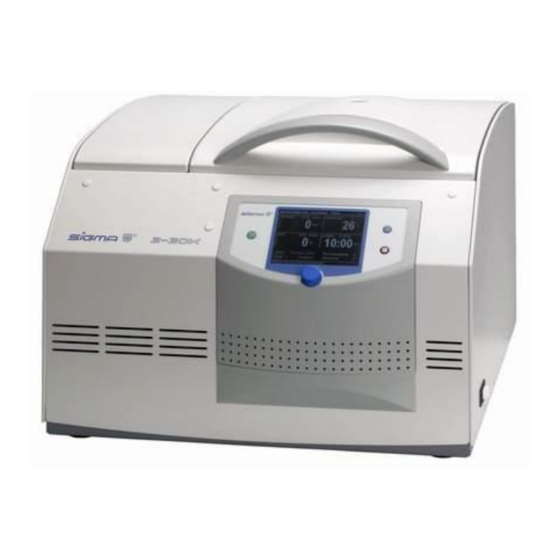
3-30K Design of the Centrifuge Design of the Centrifuge Overview Mains power switch Stop key Lid key Display Start key Function knob Fig. 2.1: Total view of the centrifuge Name plate (see page 12) Mains power input Equipotential bonding screw Fig. -
Page 12: Name Plate
3-30K Design of the Centrifuge Name Plate Manufacturer and registered office Type name Serial number Max. speed Kinetic energy Max. density Nominal voltage Input fuse Symbol for special disposal (see chapter 9) CE mark in accordance with the directive 94/9/EC... -
Page 13: Safety
3-30K Safety Safety Marking of the Unit International symbols used for SIGMA centrifuges: Gefährliche elektrische Spannung Dangerous voltage Courant haute tension Achtung, Betriebsanleitung lesen Attention, consult instruction manual Attention, consulter mode d'emploi Ein (Netzverbindung) On (Power) Marche (mise sous tension) -
Page 14: Explanation Of The Symbols And Notes
3-30K Safety Explanation of the Symbols and Notes This operating manual uses the following names and symbols to indicate hazards: This symbol stands for a direct hazard to the life and health of persons. Non-observance of these symbols causes serious health problems up to life-endangering injuries. -
Page 15: Responsibility Of The Operator
3-30K Safety Responsibility of the Operator The operator is responsible to authorise only qualified personnel to work on the machine (see chapter 3.4 "Operating Personnel"). The areas of responsibility of the personnel concerning the operation, maintenance, and care of the unit must be clearly defined. -
Page 16: Safety Instructions
Stop the centrifuge immediately in the event of a malfunction (see chapter 7 "Malfunctions and Error Correction") or contact the service of SIGMA Laborzentrifugen GmbH (see 7.3 "Service Contact"). Ensure that all repairs are performed only by authorized and specialized personnel (see 7.3 "Service Contact"). -
Page 17: Fire Prevention
3-30K Safety Prior to any start-up, check the centrifuge, rotor, and accessories for signs of damage that can be discerned from the outside. Special attention must be paid to all of the rubber parts (e.g. motor cover, lid seal, adapter) in terms of visible structural changes. -
Page 18: Resistance Of Plastics
3-30K Safety Do not store any dangerous goods in the safety area of the centrifuge. Do not stay in the safety area longer than what is absolutely necessary for the operation of the centrifuge. Only use the centrifuge with rotors and accessories that have been approved by the manufacturer. -
Page 19: Safety Devices
3-30K Safety Fig. 3.1: Different service life – engraving on the bucket/rotor Refer to the table of rotors and accessories with a different service life ( see chapter 1 “Appendix”) Safety Devices 3.7.1 Lid Lock Device The centrifuge can only be started when the lid is properly closed. -
Page 20: Imbalance Monitoring System
3-30K Safety 3.7.5 Imbalance Monitoring System A dialog box may pop up or emit a sound signal in order to indcate that the centrifuge is in the inadmissible imbalance range. If the rotor is loaded unevenly, the drive will be switched off in the acceleration phase or during the run. -
Page 21: Storage And Transport Dimensions And Weight
3-30K Storage and Transport Storage and Transport Dimensions and Weight Height: 460 mm Height with opened lid: 890 mm Width: 570 mm Depth: 616 mm Weight: 100 kg Fig. 4.1: Dimensions and weight Storage Conditions The centrifuge can be stored for up to a year without any problems. -
Page 22: Set-Up And Connection Unpacking The Centrifuge
3-30K Set-up and Connection Set-up and Connection Unpacking the Centrifuge The centrifuge is packaged in a wooden crate. After taking off the lid, remove the side panels. Remove the packaging material. Lift the centrifuge upwards with a lifting device to lift it safely. -
Page 23: Installation Site
3-30K Set-up and Connection Installation Site Operate the centrifuge only in closed and dry rooms. All the energy supplied to the centrifuge is converted into heat and emitted to ambient air. Ensure sufficient ventilation. Keep a safety distance of at least 30 cm around the centrifuge so that the vents in the centrifuge remain fully effective. -
Page 24: Using The Centrifuge Initial Start-Up
3-30K Using the Centrifuge Using the Centrifuge Initial Start-Up Before the initial start-up, please ensure that your centrifuge is properly set up and installed (see chapter 5 "Set-up and Connection"). Switching the Centrifuge ON Press the mains power switch on the right side of the front (see Fig. -
Page 25: Installation Of Angle Rotors With A Hermetically Sealed Lid
3-30K Using the Centrifuge 6.2.2.2 Installation of Angle Rotors with a Hermetically Sealed Lid Screw the rotor cover onto the rotor and tighten it. Lower the rotor with the cover onto the motor shaft . Insert the rotor tie-down screw into the motor shaft. Tighten the rotor tie-down screw with 10 Nm using the supplied rotor wrench so that the spring washer assembly is compressed tightly. -
Page 26: Adapters
3-30K Using the Centrifuge Fig. 6.2: Permissible loading of the swing-out rotor with different tube sizes Fig. 6.3: Permissible loading of the swing-out rotor 6.2.2.4 Adapters In order to ensure easy handling, even if vessels of various sizes are used, carrier systems were developed. -
Page 27: Spincontrol Comfort
3-30K Spincontrol Comfort – Using the Centrifuge Spincontrol Comfort 6.3.1 Operating Panel 1 Centrifuge display 2 Function key 3 Start key 4 Stop key 5 Lid key Fig. 6.4: Operating Panel The centrifuge is started directly via the operating panel. When the centrifuge is switched on, all of the operating keys and displays will be illuminated for a short time. -
Page 28: Manual Mode
3-30K Using the Centrifuge – Spincontrol Comfort 6.3.3 Manual Mode 6.3.3.1 Starting a Centrifugation Run The centrifuge is ready for operation when the start key is illuminated. Press the start key in order to start a centrifugation run. 6.3.3.2 Interrupting a Centrifugation Run Press the stop key in order to interrupt a centrifugation run. -
Page 29: Standard Menu
3-30K Spincontrol Comfort – Using the Centrifuge 6.3.3.5 Standard Menu If this area is inverted, the alteration mode is active (here in combination with the speed). Fig. 6.6: "Set" function Speed In the upper section of the field, the set speed of the centrifuge is displayed. - Page 30 3-30K Using the Centrifuge – Spincontrol Comfort The set value is indicated in hours, minutes, and seconds. The actual value has the same units as the set value and is displayed in hours:minutes, or in minutes:seconds if the value is below 10 minutes.
- Page 31 3-30K Spincontrol Comfort – Using the Centrifuge The centrifuge 4-16KH with a heater enables the preselection of temperatures up to +60°C. The maximum rotor temperature that can actually be reached is 40-60°C, depending on the rotor and speed. Program In this field, the number of the actual program is displayed.
-
Page 32: Parameter Menu
3-30K Using the Centrifuge – Spincontrol Comfort Identifying and adapting incorrectly set rotors The centrifuge automatically identifies the rotor that is being currently used. If the system identifies a different rotor than the one that is set, if there are no different buckets for this rotor, and if the speed has not been adapted manually, the rotor input will be adapted automatically. - Page 33 3-30K Spincontrol Comfort – Using the Centrifuge Density If the density of the liquid is higher than 1.2 g/cm , the value must be adapted manually. This, in turn, reduces the maximum final speed (see 11.4.2 “Density“). A downward facing arrow ( ) will be displayed in the speed field.
- Page 34 3-30K Using the Centrifuge – Spincontrol Comfort An entry will interrupt the rapid cooling program. There will be no message when the set temperature is reached. If no new runtime is entered, the centrifuge will continue to run infinitely (continuous run).
- Page 35 3-30K Spincontrol Comfort – Using the Centrifuge Unblocking a function Select the button "Delete code". Enter the code and confirm the entry. The function is now unblocked. Changing the code Select the button "Change code". Enter the old code and confirm the entry.
-
Page 36: Curves Menu
3-30K Using the Centrifuge – Spincontrol Comfort Cycles For each rotor/bucket combination, the number of cycles and runtime are stored. Buzzer In this menu, a sound signal can be selected for the end of a centrifugation run an imbalance message an error message. - Page 37 3-30K Spincontrol Comfort – Using the Centrifuge Creation of the curves for variable accelerations and decelerations In the configuration mode, select the field "Curves" and confirm the selection. The curve overview will be displayed. Select the time display and confirm the selection.
-
Page 38: Modification Of The Contrast
3-30K Using the Centrifuge – Spincontrol Comfort Cut: The curve speed in an interval will automatically be limited to the set speed in the operating mode. Admit: The curve speed in an interval will be allowed. Cancel: A stop occurs. Starting is impossible without a change of the curve speed in an interval. -
Page 39: Modification Of Parameter Values During The Centrifugation Run
3-30K Spincontrol Comfort – Using the Centrifuge 6.3.3.11 Modification of Parameter Values during the Centrifugation Run (see 6.3.3.4 “Selection, Display, and Modification of Data"): Modification possible Modification (De-)Activation impossible possible Speed Rotor Continuous run Program Standstill cooling Runtime Radius Start delay... - Page 40 3-30K Using the Centrifuge – Spincontrol Comfort 6.3.4.1 Loading a Program 1. Loading a program by entering a program number Select the program field ("PROG-") and confirm the selection. Turn the knob. As a result, all of the programs that have already been saved and the current ("--") setting will be displayed one...
-
Page 41: Deleting A Program
3-30K Spincontrol Comfort – Using the Centrifuge 6.3.4.3 Deleting a program Select the double arrow ( ) next to the program selection list and confirm the selection. An overview with all of the programs that have already been saved will be displayed. -
Page 43: Spincontrol Professional
3-30K Spincontrol Professional – Using the Centrifuge Spincontrol Professional 6.4.1 Operating Panel The centrifuge is started directly via the operating panel. When the centrifuge is switched on, all of the operating keys and displays will be illuminated for a short time. It is now ready for operation. -
Page 44: Manual Mode
3-30K Using the Centrifuge – Spincontrol Professional 6.4.3 Manual Mode 6.4.3.1 Starting a Centrifugation Run The centrifuge is ready for operation when the start key is illuminated. Press the start key in order to start a centrifugation run. 6.4.3.2 Interrupting a Centrifugation Run Press the stop key in order to interrupt a centrifugation run. -
Page 45: Standard Menu
3-30K Spincontrol Professional – Using the Centrifuge 6.4.3.5 Standard Menu Abb. 6.29: Standard Menu This menu is displayed a few seconds after the centrifuge has been switched on. The following parameters can be displayed and modified: Speed In the upper section of the field, the set speed of the centrifuge is displayed. - Page 46 3-30K Using the Centrifuge – Spincontrol Professional Runtime The set runtime is displayed in the upper section of this field, with the remaining runtime shown below. The runtime is defined as the period from the start of the centrifuge to the beginning of the deceleration phase.
- Page 47 3-30K Spincontrol Professional – Using the Centrifuge Identifying and adapting incorrectly set rotors The centrifuge automatically identifies the rotor that is being currently used. If the system identifies a different rotor than the one that is set, if there are no different buckets for this rotor, and if the speed has not been adapted manually, the rotor input will be adapted automatically.
- Page 48 3-30K Using the Centrifuge – Spincontrol Professional Acceleration This function is used to select an acceleration curve. One can select a linear rise (curves 0-9) or a quadratic rise (curves 10-19). The acceleration curves 20-29 can be programmed as desired.
- Page 49 3-30K Spincontrol Professional – Using the Centrifuge 6.4.3.7 Parameter Menu Fig. 6.33: Parameter menu Process Standstill cooling Depending on the substances to be centrifuged, it may make sense to precool the centrifuge. The precooling prevents the cooled samples in the uncooled centrifuge from heating up to an inadmissible temperature.
- Page 50 3-30K Using the Centrifuge – Spincontrol Professional Fig. 6.34: Rapid cooling program "RAPID_TEMP" The program will only be loaded if the actual temperature is above the set temperature. The program runs until the set value is reached. Then, a sound signal is issued, and the standstill colling is activated.
- Page 51 3-30K Spincontrol Professional – Using the Centrifuge Temperature control The temperature control function is used to set the desired threshold "delta T" in steps of 1°C or 1°F. Select the temperature control function and confirm the selection. Set the desired threshold "delta T".
- Page 52 3-30K Using the Centrifuge – Spincontrol Professional Curve Editor The Curve Editor function can be used to create and edit user- specific acceleration and deceleration curves. General information concerning this subject can be found in chapter 11.3 "Acceleration and Deceleration Curves".
-
Page 53: Setup Menu
3-30K Spincontrol Professional – Using the Centrifuge Fig. 6.35: Curve editor Programmable curves are not profiles. In order to create a profile, they must be combined in a program together with a run phase (see 6.4.4 "Program Mode"). Brakeless deceleration as of a set speed If this function is active, the drive will be disconnected if the actual speed is below the set speed. - Page 54 3-30K Using the Centrifuge – Spincontrol Professional Function Open lid after run The Auto-Lid-Open function must be activated so that the lid opens automatically at the end of the operation. When the lid is open, the cooling is not active. Samples may warm Program rotation See chapter 6.4.4.4 "Automatic Program rotation"...
-
Page 55: Help Menu
3-30K Spincontrol Professional – Using the Centrifuge Invert This function switches the display from black/white to white/black. Buzzer In this menu, a sound signal can be selected for the end of a centrifugation run an imbalance message an error message. -
Page 56: Changing The Contrast
3-30K Using the Centrifuge – Spincontrol Professional 6.4.3.10 Changing the Contrast Press and hold the stop key and turn the function knob one notch to the left. A dialog box will be displayed. Adjust the contrast of the centrifuge display and confirm the change. -
Page 57: Program Mode
3-30K Spincontrol Professional – Using the Centrifuge 6.4.4 Program Mode A program contains all data that are required for a centrifuge run. Attention: Temperature profiles cannot be created! With a program, certain sedimentation results can be repeated under identical conditions. - Page 58 3-30K Using the Centrifuge – Spincontrol Professional 6.4.4.2 Saving a Program Enter the parameters that are to be included in the program. Select the option „Progr“ and confirm the selection. The program selection list will be displayed. Select a storage location from the program selection list.
-
Page 59: Options For Data Input And Output (Can Be Retrofitted)
3-30K Spincontrol Professional – Using the Centrifuge 6.4.4.4 Automatic Program Rotation With the program rotation, programs can be run directly one after another. Select "Program rotation" in the "Setup“ menu. Fig. 6.42: Program rotation function The current program is loaded and can be started. After the end of the run, the next program will be loaded and started automatically. -
Page 60: Switching The Centrifuge Off
4-16K Malfunctions and Error Correction Switching the Centrifuge OFF Open the centrifuge when it is not in use so moisture can evaporate. This prevents the increased wear of the motor bearings. Press the mains power switch on the front of the right side. Malfunctions and Error Correction General Malfunctions Malfunctions are indicated by a dialogue box. -
Page 61: Emergency Lid Release
3-30K Malfunctions and Error Correction Lid cannot be opened Lid lock has not released Unlock the lid manually (see 7.1.1) and contact service Lid seal sticks Clean the lid seal and apply talcum powder Temperature value cannot be Condenser dirty Clean the condenser. -
Page 62: Error Codes
3-30K Malfunctions and Error Correction Do not unlock or open the lid unless the rotor is at a standstill. If the lid is opened via the emergency lid release system during a centrifuge run, the centrifuge will be switched off immediately and decelerate in an unbraked manner. -
Page 63: Service Contact
[Service Area] or contact SIGMA Laborzentrifugen GmbH An der Unteren Söse 50 37520 Osterode (Germany) Tel. +49 (0) 55 22 / 50 07-84 25 Fax +49 (0) 55 22 / 50 07-94 25 E-mail: service@sigma-zentrifugen.de... -
Page 64: Maintenance And Service
3-30K Maintenance and Service Maintenance and Service The centrifuge, rotor, and accessories are subject to high mechanical stress. Thorough maintenance performed by the user extends the service life and prevents premature failure. If corrosion or other damage occurs due to improper care, the manufacturer cannot be held liable or subject to any warranty claims. -
Page 65: Accessories
3-30K Maintenance and Service 8.1.2 Accessories For the care of the accessories, special safety measures must be considered as these are measures that will ensure operational safety at the same time. Immediately rinse off the rotor, buckets, or accessories under running water if they have come into contact with any liquids that may cause corrosion. -
Page 66: Load-Bearing Bolts
3-30K Maintenance and Service Check the material regularly (at least once a month) for - cracks - visible damage of the surface - pressure marks - signs of corrosion - other changes. Check the bores of the rotors and multiple carriers. -
Page 67: Condenser
3-30K Maintenance and Service 8.1.6 Condenser In order to cool the refrigerant that is compressed by the refrigeration unit, a lamellar condenser is used. It is cooled by air. Dust and dirt obstruct the cooling flow of air. Dust on condenser pipes and lamellas reduces the heat exchange and thus the performance of the refrigeration unit. -
Page 68: Autoclaving
3-30K Maintenance and Service 8.2.1. Autoclaving The service life of the accessories essentially depends on the frequency of autoclaving and use. Replace the accessories immediately when the parts show changes in color or structure or in the occurrence of leaks etc. -
Page 69: Service
[Service Area] or contact SIGMA Laborzentrifugen GmbH An der Unteren Söse 50 37520 Osterode (Germany) Tel. +49 (0) 55 22 / 50 07-84 25 Fax +49 (0) 55 22 / 50 07-94 25 E-mail: service@sigma-zentrifugen.de... -
Page 70: Return Of Defective Parts
3-30K Maintenance and Service Return of defective parts Although we exercise great care during the production of our products, it may be necessary to return a unit or accessory to the manufacturer. In order to ensure the quick and economical processing of returns of centrifuges, spare parts, or accessories, we require complete and extensive information concerning the process. -
Page 71: Disposal
This symbol means that it is not permissible to dispose of the unit among household trash. You can return these centrifuges free of cost to SIGMA Laborzentrifugen GmbH. Ensure that the unit is decontaminated. Fill in a declaration of decontamination. -
Page 72: Technical Data
3-30K Technical Data Technical Data Manufacturer: S I G M A Laborzentrifugen GmbH An der Unteren Söse 50 37520 Osterode (Germany) Type: 3-30K Electr. Connection: see name plate Protection class: IP Code: Connected load (kVA): Power consumption (kW): 1.26 Max. current consumption (A): 7.5 (at 220-240 V / 50 Hz) -
Page 73: Appendix
3-30K Appendix Appendix 11.1 Suitable Accessories Part no. Description Max. speed Max. (rpm) gravitational field (x g) 11222 Swing-out rotor for microtiter plates, incl. 1 set carriers no. 13222, max. height of plates 56 mm Radius corner 12.3 cm 3 000 1 238 Radius max. - Page 74 3-30K Appendix Part no. Description Max. speed Max. (rpm) gravitational field (x g) 14035 Round carrier for 1 tube 30 ml, flat bottom or skirt, max. Ø 25/31 x 65 - 95 mm, e.g. Sterilin tube 30 ml, Barloworld Scientific Ltd., 1 set = 2 pcs.
- Page 75 3-30K Appendix Part no. Description Max. speed Max. (rpm) gravitational field (x g) 12349 Angle rotor 48 x 1.5/2.0 ml, for reaction vials, e.g. no. 15008, 15040, incl. aluminium hermetic lid no. 17349, max. radius 10.0 cm, min. radius 6.5 cm...
- Page 76 3-30K Appendix Part no. Description 13021 Adapter for PCR-tube 0.2 ml, e.g no. 15042, suitable for 12110, 12131, 12154, 12349, 1 set = 2 pcs. 13059 Adapter for 1 round bottom tube 10 ml, max. Ø 16.2/19 x 75 - 85 mm, e.g. no. 15000, 15010, 1 set = 2 pcs.
- Page 77 3-30K Appendix Part no. Description 13085 Stainless steel tube 85 ml, Ø 38 x 103 mm, sealable with cap no. 17185, suitable for 12155, 12159 17185 Round stainless steel sealing cap for 13085 15076 Polypropylene Co-Polymer (PPCO) tube 78 ml, Ø 38 x 112 mm, incl. screw cap, suitable...
-
Page 78: Maximum Speed For Tubes
3-30K Appendix Further Accessories Part no. Description 16018 Rubber adapter for special glass tube 15 ml no. 15022 and for glass tube no. 15085, suitable for 12150, 12156, 1 set = 2 pcs. 16019 Rubber adapter for special glass tubes no. 15015, 15022 and 15085, suitable for 12155, 12159, 1 set = 2 pcs. -
Page 79: Grafical Representation Of The Rotors
3-30K Appendix 11.2 Grafical Representation of the Rotors The graphical representation of the rotors shows the maximum and minimum radii of the accessories used. If necessary, the values must be manually calculated (see 11.4.1 "RCF“, page 82). Fig 11.1: Minimum and maximum radius of a swing-out rotor Fig. -
Page 80: Acceleration And Deceleration Curves
3-30K Appendix 11.3 Acceleration and Deceleration Curves 11.3.1 Linear Curves The slope of the fixed acceleration curves defines the time that is required to accelerate the rotor by 1,000 rpm. Linear as well as quadratic curves are numbered in the direction of increasing acceleration (from right to left). -
Page 81: Quadratic Curves
3-30K Appendix Linear curve no. Slope 4 [rpm / sec] 6 [rpm / sec] 8 [rpm / sec] 17 [rpm / sec] 25 [rpm / sec] 33 [rpm / sec] 50 [rpm / sec] 100 [rpm / sec] 200 [rpm / sec] 1000 [rpm / sec] Fig. -
Page 82: Formulae - Mathematical Relations
3-30K Appendix Quadratic curve no. Time until 1,000 rpm Slope as of 1,000 rpm 500 sec 4 [rpm / sec] 333 sec 6 [rpm / sec] 250 sec 8 [rpm / sec] 118 sec 17 [rpm / sec] 80 sec... - Page 83 3-30K Appendix Fig. 11.7: Speed-Grravitational-Field Diagram Version 12/2008, Rev. 1.11 of 27/01/2012 Translation of the original operating manual...
-
Page 84: Table Of Rotors And Accessories With A Different Service Life
3-30K Appendix Table of rotors and accessories with a different service life Rotors and accessories with a different service life If other no data concerning the service life are engraved on the rotor or accessory, rotors and buckets must be checked by the manufacturer after 10,000 cycles. After 50,000 cycles, rotors must be scrapped for safety reasons. -
Page 85: Resistance Data
3-30K Appendix Resistance Data Resistance Data Resistant at +20 °C - no data 1 resistant 2 practically resistant 3 partially resistant 4 not resistant Medium Formula Acetaldehyde Acetamide saturated Acetone Acrylonitrile Allyl alcohol Aluminum chloride AlCl saturated Aluminum sulfate Ammonium chloride... - Page 86 3-30K Appendix Resistant at +20 °C - no data 1 resistant 2 practically resistant 3 partially resistant 4 not resistant Medium Formula Dioxane Dipropylene glycol (mono)methyl ether Ethyl acetate Ethylene chloride Ferrous chloride FeCl saturated Formaldehyde solution Formic acid Furfural...
- Page 87 3-30K Appendix Resistant at +20 °C - no data 1 resistant 2 practically resistant 3 partially resistant 4 not resistant Medium Formula Potassium hydrogen carbonate CHKO saturated Potassium hydroxide Potassium hydroxide Potassium nitrate Potassium permanganate KMnO Pyridine Resorcinol Silver nitrate...
-
Page 89: Ec-Declaration Of Conformity
EC-Declaration of Conformity... - Page 91 3-30K Index Index Acceleration....................... 29, 32, 43, 48 Acceleration curve ..................32, 36, 39, 48, 56, 80 Accident prevention ......................15 Acid ........................18, 64, 85, 87 Activating/deactivating the help function ................55 Adapters ........................26, 66, 78 Adapters, steel tubes and plastic tubes................75 Alkaline solutions ......................
- Page 92 3-30K Index Connection........................... 23 Contamination........................ 17, 64 Continuous heat resistance....................67 Continuous run ....................30, 39, 46, 56 Contrast ..........................38 Contrast dialog box ......................38 Copyright ..........................10 Corrosion ....................16, 18, 26, 64, 65, 66 Corrrosion ..........................65 Cost estimate........................70 Cracks ........................
- Page 93 3-30K Index Form for the return of defective parts ................... 70 Formulae - mathematical relations ..................82 Freezing-over of the compressor ................... 33, 49 Function..........................54 Further accessories ......................78 Fuse ............................ 23 Fuses........................... 23 Fuses have tripped ......................60 General conditions .........................
- Page 94 3-30K Index Lid lock has not released ..................... 61 Lid seal sticks ........................61 Limited service life ....................... 18 Linear curves ........................80 Load-bearing bolts ....................... 66 Loading a program......................40, 57 Loading a program by entering a program number .............. 40 Loading a program from the program selection list...............
- Page 95 3-30K Index Pathogenic substances..................17, 64, 65, 67 Pivot bearing........................66 Plastic accessories ......................65 Potential hazard to the life and health .................. 14 Potentially hazardous situation .................... 14 Power consumption ....................... 12, 72 Power cord ......................23, 61, 64 Power cord is not plugged in....................
- Page 96 3-30K Index Runtime fine......................... 54 Runtime from set speed ....................... 54 Safety area .......................... 17 Safety class ......................... 23 Safety distance ......................17, 23 Safety instructions...................... 9, 24, 25 Safety instructions for centrifugation ..................17 Safety-conscious work ......................15 Saving a program......................40, 58 Scope of supply ........................
- Page 97 3-30K Index Storage and transport ......................21 Storage conditions ....................... 21 Storage temperature ......................21 Stress-corrosion........................65 Structural changes....................... 16 Suitable accessories ...................... 25, 73 Supply voltage ........................23 Swing-out rotor ........................25 Switching the centrifuge OFF....................60 Switching the centrifuge ON....................24 System..........................
- Page 99 3-30K Short Operating Instructions Pay attention to the detailed Operating Manual, especially to the safety instructions in chapter 3! Mains power switch Stop key Lid key Display Start key Function knob Total view of the centrifuge Name plate Mains power input...
- Page 100 3-30K Short Operating Instructions Enter run parameters: Spincontrol Comfort Spincontrol Professional Manual Mode Select a parameter by pressing or turning the function knob. The selected field will be inverted. Manual Mode Press the function knob in order to activate the modification mode. "SET"...
Need help?
Do you have a question about the 3-30K and is the answer not in the manual?
Questions and answers