
Related Manuals for Sigma 3-16P


Summary of Contents for Sigma 3-16P
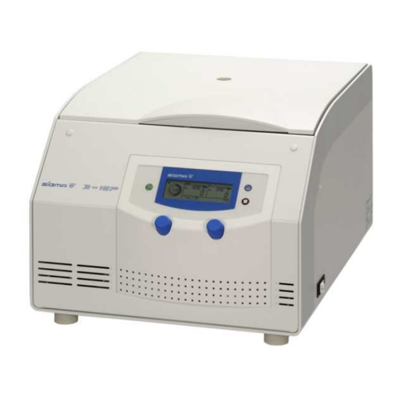
- Page 1 Operating Manual Centrifuge 3-16P Please retain for later use! Version 06/2007, Rev. 1.15.1 of 05/10/2011 - sb Translation of the original operating manual...
- Page 3 In case of inquiries please state the following number: Serial number: © Copyright by Sigma Laborzentrifugen GmbH An der Unteren Söse 50 37520 Osterode am Harz Germany Phone +49 (0) 55 22 / 50 07-0 +49 (0) 55 22 / 50 07-12 E-mail: info@sigma-zentrifugen.de...
-
Page 7: Table Of Contents
Table of Contents General Information Importance of the Operating Manual Intended Use Technical Data 1.3.1 Ambient Temperature Scope of Supply Standards and Regulations Safety Instructions and Hazard Warnings Symbols used in the Safety Instructions Symbols used in the Operating Manual Informal Notes on Safety Safety Instructions for Centrifugation 2.4.1... - Page 8 Using the Centrifuge Description 5.1.1 Operating Elements 5.1.1.1 Operating Panel 5.1.1.2 Name Plate 5.1.2 Construction and Constructive Safety Measures 5.1.3 Drive 5.1.4 Operation and Display 5.1.5 Electronic System 5.1.6 Safety Devices 5.1.6.1 Lid Lock and Lid Closing Device 5.1.6.2 Standstill Monitoring 5.1.6.3 System Check 5.1.6.4 Ground Wire Check 5.1.6.5 Imbalance Monitoring System...
- Page 9 5.3.4 Rotor Preselection 5.3.5 Program 5.3.5.1 Saving the Current Settings 5.3.5.2 Calling Up Stored Programs 5.3.6 Lockdown 5.3.6.1 Permanent Lockdown 5.3.7 Activating/Deactivating the Automatic Lid Opening Function 5.3.8 Activating/Deactivating the Sound Signal Malfunctions and Error Correction Error Mode Error Correction 6.2.1 No Indication on the Display 6.2.2...
- Page 10 Warranty and Liability Suitable Accessories 10.1 Maximum speed for tubes 10.2 Graphical Representation of the Rotors Appendix 11.1 Formulae – Mathematical Relations 11.1.1 Relative Centrifugal Force (RCF) 11.1.2 Density 11.1.3 Speed-Gravitational-Field-Diagram 11.2 Table of rotors and accessories with a different service life 11.3 Resistance Data Index Version 06/2007, Rev.
-
Page 11: General Information
(see BGR 500, chapter 2.11, part 3). They are solely intended for this purpose. Any other use beyond this area of application is regarded as improper use. SIGMA Laborzentrifugen GmbH cannot be held liable for any damage resulting from such improper use. -
Page 12: Technical Data
Technical Data Manufacturer: S I G M A Laborzentrifugen GmbH An der Unteren Söse 50 37520 Osterode Type: 3-16P Electr. connection: See name plate Protection class: IP code: Connected load (kVA): 0.82 Power consumption (kW): Max. current consumption (A): 3.2 (at 220-240 V / 50-60 Hz) 6.8 (at 120 V / 60 Hz) -
Page 13: Scope Of Supply
Scope of Supply The centrifuge comprises: • 1 connecting cable depending on the voltage variant • 1 rotor wrench Part no. 930 100 • 20 ml slushing oil Part no. 70 104 • 1 tube of grease for load-bearing bolts Part no. -
Page 14: Safety Instructions And Hazard Warnings
Nicht mit dem Hausmüll entsorgen Do not dispose as part of domestic waste Ne pas jeter avec les déchets ménager Fig. 2.1: Symbols used for SIGMA centrifuges Version 06/2007, Rev. 1.15 of 16/09/2011 - sb page 14 of 75 Translation of the original operating manual... -
Page 15: Symbols Used In The Operating Manual
Symbols used in the Operating Manual Symbols used in the Operating Manual: Symbol Title Gefährliche elektrische Spannung Dangerous voltage Courant haute tension Achtung, mögliche gefährliche Situation Attention, potentially dangerous situation Attention, situation potentiellement dangereuse Hinweis auf wichtige Sachverhalte Attention! Note concerning important facts Information très importante Fig. -
Page 16: Safety Instructions For Centrifugation
Safety Instructions for Centrifugation • Ensure that the centrifuge was set up properly (see section 4.2 “Installation”, page 23). • Check the centrifuge, rotor, and accessories for external signs of damage prior to start-up. • Do not use the centrifuge with rotors and accessories that have not been approved by the manufacturer. -
Page 17: Special Instructions
• Stop the centrifuge immediately in the event of a malfunction. Eliminate the problem (see 6.2, page 43 ff) or inform the SIGMA Laborzentrifugen GmbH service team (see 6.2.7 "Service Contact", page 46). Version 06/2007, Rev. 1.15 of 16/09/2011 - sb... -
Page 18: Resistance Of Plastics
2.4.2 Resistance of Plastics Chemical influences have a strong effect on the polymeric chains of plastics, and therefore, on their physical properties. Plastic parts can be damaged if solvents, acids, or alkaline solutions are used. • Please refer to the resistance table (see 11.2, page 69)! Prohibited Centrifuging Operations and Hazard Warnings Under the rules stipulated by the German trade association BGR 500, chapter 2.11, part 3, the operator is obliged to:... -
Page 19: Special Hazards
• Do not spin any substances that could damage the material of the rotors and buckets of the centrifuge in any way. Highly corrosive substances, for example, damage the material and affect the mechanical strength of the rotors and buckets. •... -
Page 20: Checks By The Operator
Checks by the Operator Check all of the safety-relevant parts of the centrifuge at least once per month for any visible signs of damage (e.g. cracks, corrosion). This applies particularly to the following: • Concentricity of the motor shaft: − Visual inspection: Slowly rotate the rotor by hand without the rotor tie- down screw. -
Page 21: Transport And Storage
Transport and Storage Dimensions and Weight Depth: 600 mm Width: 460 mm Height: 355 mm Weight: 48 kg Fig. 3.1: Dimensions and weight Notes on Transport • Always lift the centrifuge with a lifting device or with a sufficient number of people helping you. -
Page 22: Set-Up And Connection
Set-up and Connection Unpacking the Centrifuge The centrifuge is packaged in a slip-lid box. • Remove the upper part of the box. • Take out the box containing the accessories. • Remove the upper foam cushion. • Remove the slip-lid box. •... -
Page 23: Installation
The operating voltage on the name plate must correspond to the local supply voltage! SIGMA laboratory centrifuges are units of safety class I and have a three-wire power cord with a IEC C13 connector. They are equipped with temperature fuses. -
Page 24: Using The Centrifuge
Using the Centrifuge Description 5.1.1 Operating Elements Mains power switch Stop key Lid key Display Start key Left rotary knob Right rotary knob Fig. 5.1: Total view of the centrifuge Name plate Equipotential bonding screw Mains power input Fig. 5.2: Rear view of the centrifuge Version 06/2007, Rev. -
Page 25: Operating Panel
5.1.1.1 Operating Panel Start key Time display Speed display RCF display Lid key Stop key Display for rotor, deceleration curve and programs Rotary knobs Fig. 5.3: Operating Panel The centrifuge is started directly via the operating panel. When the centrifuge is switched on, all of the operating keys and displays will be illuminated for a short time. -
Page 26: Construction And Constructive Safety Measures
5.1.2 Construction and Constructive Safety Measures The centrifuge is installed within a solid construction. On the back, the lid is secured by solid hinges and on the front by one lid lock. 5.1.3 Drive The drive motor is a well-dimensioned, collector-less asynchronous motor. 5.1.4 Operation and Display The display is a hermetically sealed LCD display. -
Page 27: Safety Devices
5.1.6 Safety Devices Apart from the mentioned passive safety devices due to the solid design, the following active precautions are in place for your safety: 5.1.6.1 Lid Lock and Lid Closing Device The centrifuge can only be started when the lid is properly closed. The electrical locks must be locked. -
Page 28: Initial Start-Up
Initial Start-Up Before the initial start-up, please ensure that your centrifuge is properly set up and installed (see 4.2 "Installation", page 23). 5.2.1 Switching the Centrifuge ON • Press the mains power switch on the right side of the front (see Fig. 5.1, page 24). -
Page 29: Installation Of Rotors
5.2.3 Installation of Rotors • Open the centrifuge lid by pressing the lid key. • Unscrew the rotor tie-down screw from the motor shaft (anti-clockwise). • Lower the rotor with its central bore straight down onto the motor shaft. • Tighten the rotor tie-down screw clockwise with the supplied rotor wrench with 7.5 Nm. -
Page 30: Installation Of Angle Rotors With A Hermetically Sealed Lid30
5.2.3.1 Installation of Angle Rotors with a Hermetically Sealed Lid • Screw the rotor cover onto the rotor and tighten it. • Lower the rotor with the cover onto the motor shaft. • Insert the rotor tie-down screw into the motor shaft. Tighten the rotor tie-down screw with 7.5 Nm using the supplied rotor wrench so that the spring washer assembly is compressed tightly. -
Page 31: Installation Of Accessories
5.2.4 Installation of Accessories • Only use vessels that are suitable for the rotor (see chapter 10 "Suitable Accessories", page 55). • Load all of the compartments of the swing-out rotors. • Always load the opposite compartments of the rotors with the same accessories and filling to avoid imbalance. -
Page 32: Carrier Systems
5.2.4.1 Carrier Systems In order to ensure easy handling, even if vessels of various sizes are used, carrier systems were developed. • Load the opposite carriers with the same number of vessels and with the same weights in order to avoid imbalance. •... -
Page 33: Starting The Centrifuge
• If other data concerning the service life are engraved on the rotor or bucket, these data shall apply accordingly: For example, a bucket with the engraving “max cycles = 10,000” has a service life of 10,000 cycles, and a rotor with the engraving “Exp.Date 02/15” must be scrapped in Feburary 2015 at the latest (see fig. -
Page 34: Softstart And Softstop Function
5.2.7.2 Softstart and Softstop Function The softstart function is used to extend the acceleration time, whereas the softstop function is used to extend the deceleration time. The current combination is shown on the display. The stop key can be used to cyclically select various combinations: •... -
Page 35: Time
5.3.1 Time The runtime of the centrifuge can be set at different intervals in a range from 10 seconds to 11 hours and 59 minutes. To select the desired centrifugation time: • Turn the left rotary knob until “set” appears in the lower left area of the display (Fig 5.11). -
Page 36: Short Run
5.3.1.2 Short Run The short run enables the user to perform a short-time centrifugation with maximum power without changing the set parameters. The short run can only be started when the centrifuge is at a standstill. • Keep the start key pressed during the short run. The centrifuge accelerates at maximum power until the maximum speed of the rotor is reached.The start key flashes;... -
Page 37: Speed
5.3.2 Speed The desired speed of the centrifuge (revolutions per minute) can be set here (15,000 rpm in the example shown below). When the maximum permissible speed of the rotor is reached, the “max” display lights up. To preselect a speed value: •... -
Page 38: Relative Centrifugal Force (Rcf)
5.3.3 Relative Centrifugal Force (RCF) The relative centrifugal force (RCF) is the acceleration that the sample is subject The RCF value is determined by the rotor geometry and speed. The RCF and speed values, therefore, depend on each other. When the maximum permissible RCF value of the rotor is reaches, the "max"... -
Page 39: Rotor Preselection
5.3.4 Rotor Preselection The centrifuge SIGMA 3-16P is equipped with an automatic rotor identification system. After the installation of the rotor, the rotor ID will be displayed. It is also possible to manually preselect the rotor. This is only possible at a standstill. -
Page 40: Program
5.3.5 Program The program is used to save or load certain recurrent settings of the centrifuge. This saves time and prevents typing errors. 50 different programs can be saved and called up. This is only possible at a standstill. 5.3.5.1 Saving the Current Settings To save the current settings: •... -
Page 41: Lockdown
5.3.6 Lockdown This function locks the parameters against all inadvertent changes. • Turn the left rotary knob until a padlock symbol is displayed in the upper left corner of the display (Fig. 5.19). As long as the padlock symbol is displayed, the parameters cannot be changed. 5.3.6.1 Permanent Lockdown The parameter settings can also be locked with the help of the start key when the lid is open:... -
Page 42: Activating/Deactivating The Sound Signal
5.3.8 Activating/Deactivating the Sound Signal If this function is active, a sound signal can be heard at the end of the operation as well as in the event of an error message or imbalance. • Press the lid key five times and on the fifth time hold it down for approx. two seconds. -
Page 43: Malfunctions And Error Correction
Malfunctions and Error Correction Error Mode Malfunctions are indicated by error messages with a number in the speed and rcf display. If the sound signal is activated, it sounds when the error message is displayed (see 5.3.8 "Activating/Deactivating the Sound Signal", page 42). Error Correction •... -
Page 44: Lid Cannot Be Opened
6.2.4 Lid cannot be opened − When trying to open the lid, the • Close the lid again. Press down the lid lock has not released. center of the lid until the lock audibly locks. Open the lid again. If the error occurs again, unlock the lid manually (see 6.2.5 "Emergency lid release", page 44) and call the service... -
Page 45: Error Codes
6.2.6 Error Codes Error no. Kind of error Measure Note • allow to slow down System error All these errors stop • power off/on the centrifuge or cause it to slow down. • allow to slow down 10-19 Speedometer error •... -
Page 46: Service Contact
→ [Service Area] www.sigma-zentrifugen.de • or contact SIGMA Laborzentrifugen GmbH An der Unteren Söse 50 37520 Osterode (Germany) Tel. +49 (0) 55 22 / 50 07-84 25 Fax +49 (0) 55 22 / 50 07-94 25 E-mail: service@sigma-zentrifugen.de... -
Page 47: Care And Maintenance
Care and Maintenance Cleaning and Care The centrifuge, rotor, and accessories are subject to high mechanical stress. Thorough maintenance care performed by the user extends the service life and prevents premature failure. Attention! If corrosion or other damage occurs due to improper care, the manufacturer cannot be held liable or subject to any warranty claims. -
Page 48: Accessories
7.1.2 Accessories For the care of the accessories, special safety measures must be considered as these are measures that will ensure operational safety at the same time. • Immediately rinse off the rotor, buckets, or accessories under running water if they have come into contact with any liquids that may cause corrosion. -
Page 49: Rotor, Buckets, And Multiple Carriers
7.1.3 Rotor, Buckets, and Multiple Carriers Rotors, buckets, and multiple carriers are produced with highest precision, in order to withstand the permanent high stress with high gravitational fields. Chemical reactions as well as stress-corrosion (combination of oscillating pressure and chemical reaction) can affect or destroy the metals. Barely detectable cracks on the surface can expand and weaken the material without any visible signs. -
Page 50: Glass Breakage
7.1.5 Glass Breakage • Glass particles will damage the surface coating (e.g. Eloxal) of the buckets, which will then lead to corrosion. • Glass particles in the rubber cushions of the buckets will cause glass breakage again. • Glass particles on the pivot bearing of the load-bearing bolts prevent the buckets and carriers from swinging evenly, which will cause an imbalance. -
Page 51: Autoclaving
7.2.1 Autoclaving The service life of the accessories essentially depends on the frequency of autoclaving and use. • Replace the accessories immediately when the parts show changes in color or structure or in the occurrence of leaks etc. • During autoclaving, the caps of the tubes must not be screwed on in order to avoid the deformation of the tubes. -
Page 52: Service
→ [Service Area] www.sigma-zentrifugen.de • or contact SIGMA Laborzentrifugen GmbH An der Unteren Söse 50 37520 Osterode (Germany) Tel. +49 (0) 55 22 / 50 07-84 25 Fax +49 (0) 55 22 / 50 07-94 25 E-mail: service@sigma-zentrifugen.de... -
Page 53: Return Of Defective Parts
If the product is dispatched to us in unsuitable packaging, you will be charged the cost for returning it to you in new packaging. → [Service The forms can be downloaded online from www.sigma-zentrifugen.de Area] → [Form Download] Version 06/2007, Rev. 1.15 of 16/09/2011 - sb page 53 of 75... -
Page 54: Disposal
Disposal Disposal of the Centrifuge In accordance with the directive 2002/96/EC, SIGMA centrifuges are marked with the symbol shown to the left. This symbol means that it is not permissible to dispose of the unit among household trash. • You can return these centrifuges free of cost to SIGMA Laborzentrifugen GmbH. -
Page 55: Suitable Accessories
Suitable Accessories Part no. Description Max. speed Max. (rpm) gravitational field (x g) 11180 Swing-out rotor, 4 place, for buckets no. 13180, 13190, 4 200 3 372 / 3 392 13194 13194 Bucket for hexagon adapters no. 18309 - 18312, for culture 4 200 3 313 tubes 15 and 50 ml, 1 set = 2 pcs.,... - Page 56 Part no. Description Max. speed Max. (rpm) gravitational field (x g) 18016 Rectangular carrier for 4 culture tubes 15 ml (Nunc, Corning, Falcon, Greiner) e.g. 15115, polypropylene 18017 Rectangular carrier for 10 tubes 15 ml, and tubes with stopper, max. Ø 17.5/19,5 x 80 - 112 mm, e.g. Monovettes 9 ml and 10 ml, polypropylene Rectangular carrier for 5 glass tubes 25 ml, max.
- Page 57 Part no. Description Max. speed Max. (rpm) gravitational field (x g) 11182 Swing-out rotor 12 x 50 ml culture tubes complete, no. 4 200 3 392 11180, incl. 2 sets buckets no. 13190, 2 sets adapters no. 17346 and 12 tubes no. 15151, max.
- Page 58 Part no. Description Max. speed Max. (rpm) gravitational field (x g) 17376 Round carrier for 4 round bottom tubes with screw cap 40 - 50 ml, max. Ø 29/34 x 85 - 110 mm, e.g. no. 15051, 15052, (13055 with 13350/13550 only), 1 set = 2 pcs.
- Page 59 Part no. Description Max. speed Max. (rpm) gravitational field (x g) 17109 Round aluminium sealing cap, for hermetic sealing of buckets 13104, 13130, 1 set = 2 pcs. 17111 Round polysulfone sealing cap, clear, for hermetic sealing of buckets 13104, 13130, 1 set = 2 pcs. 17006 Round carrier for 12 tubes approx.
- Page 60 Part no. Description Max. speed Max. (rpm) gravitational field (x g) 17100 Round carrier for 1 round bottom tube approx. 100 ml, max. Ø 45.5 x 85 - 105 mm, e.g. no. 15100, 15103, 15106, 1 set = 2 pcs. 17101 Round carrier for 1 round bottom tube 100 ml, max.
- Page 61 Part no. Description Max. speed Max. (rpm) gravitational field (x g) 12111 Angle rotor 10 x 10 ml, for tubes no. 15000, 15010, 15039, 14 500 17 865 incl. hermetic aluminium lid no. 17835, max. radius 7.6 cm, min. radius 2.8 cm, angle 35° 12157 Angle rotor 20 x 10 ml, for tubes e.g.
- Page 62 Part no. Description Max. speed Max. (rpm) gravitational field (x g) 13084 Adapter, for 2 tubes 10 ml, Ø 16/17.5 x 75 - 90 mm, e.g. no. 15000, 15010, 15039, 1 set = 2 pcs., suitable for 12155, 12159 Adapters, tubes and steel tubes Part no.
- Page 63 Part no. Description 13055 Stainless steel tube 50 ml, Ø 28.5 x 101.5 mm, sealable with cap no. 17054, suitable for 12150, 12156, 13082, 17052, 18051 17054 Stainless steel sealing cap for 13055 15051 Polyfluor tube 38 ml, Ø 28.5 x 107 mm, incl. screw cap, suitable for 12150, 12156, 13079, 13082, 17052, 17376, 18051 15052 Polypropylene Co-Polymer (PPCO) tube 42 ml, Ø...
- Page 64 Part no. Description 15026 Centrifuge glass tube 27 ml, max. 4.000 x g, Ø 24 x 100 mm, graduated 2 up to 25 ml in 0.5 ml increments, suitable for 17025, 18025 15033 Glass tube 32 ml, max. 4.000 x g, Ø 24 x 105 mm,suitable for 12150, 12156 with 16030 and for 12155, 12159 with 16031 15050 Centrifuge glass tube 58 ml, max.
-
Page 65: Maximum Speed For Tubes
10.1 Maximum speed for tubes Some tubes, such as centrifuge glass tubes, microtubes, culture tubes, fluoropolymer tubes and especially high-volume tubes can be used in our rotors, buckets, and adapters at higher speeds than their breaking limit. • Always fill the tubes up to their useful volume (= the volume that is stated for the tube). -
Page 66: Graphical Representation Of The Rotors
10.2 Graphical Representation of the Rotors The graphical representation of the rotors shows the maximum and minimum radii of the accessories used. If necessary, the values must be manually calculated (see 11.1.1 “RCF”, page 67). Fig. 10.1: Minimum and maximum radius of a swing-out rotor Fig. -
Page 67: Appendix
Appendix 11.1 Formulae – Mathematical Relations 11.1.1 Relative Centrifugal Force (RCF) The parameters speed, RCF, and the group rotor and radius cannot be specified independently. They are interrelated via the following formula: RCF = 11.18 x 10 x r x n If two values are given, the third value is determined by the equation. - Page 68 Fig. 11.1: Speed-gravitational-field-diagram Version 06/2007, Rev. 1.15 of 16/09/2011 - sb page 68 of 75 Translation of the original operating manual...
-
Page 69: Table Of Rotors And Accessories With A Different Service Life
11.2 Table of rotors and accessories with a different service life Rotors and accessories with a different service life If other no data concerning the service life are engraved on the rotor or accessory, rotors and buckets must be checked by the manufacturer after 10,000 cycles. After 50,000 cycles, rotors must be scrapped for safety reasons. -
Page 70: Resistance Data
11.3 Resistance Data Resistant at +20 ° C - no data 1 resistant 2 practically resistant 3 partially resistant 4 not resistant Medium Formula [%] HDPE PA PC POM PP PSU PVC PVC PTFE AL Acetaldehyde Acetamide saturated Acetone Acrylonitrile Allyl alcohol Aluminum chloride AlCl... - Page 71 Resistant at +20 ° C - no data 1 resistant 2 practically resistant 3 partially resistant 4 not resistant Medium Formula [%] HDPE PA PC POM PP PSU PVC PVC PTFE AL Dioxane Dipropylene glycol (mono)methyl ether Ethyl acetate Ethylene chloride Ferrous chloride FeCl saturated...
- Page 72 Resistant at +20 ° C - no data 1 resistant 2 practically resistant 3 partially resistant 4 not resistant Medium Formula [%] HDPE PA PC POM PP PSU PVC PVC PTFE AL Potassium hydroxide Potassium hydroxide Potassium nitrate Potassium permanganate KMnO Pyridine Resorcinol...
-
Page 73: Index
Index Acceleration curves - see also the softstart and softstop function ..............27 Acceleration time - see also the softstart and softstop function ..............35 Acid ..........................71, 72, 73 Adapter ..........................52, 66 Alkaline solutions......................18, 48, 49 Ambient temperature......................12 Angle rotor........................32, 33, 52 Auto-Lid-Open function......................42 Automatic rotor identification ....................40 Bucket .................... - Page 74 Gravitational field......................12, 50, 68 Grease for load-bearing bolts ...................13, 48, 50 Ground wire check .......................28 Ground wire connector ......................24 Hazard warnings ..................14, 18, 30, 31, 55 Hazards........................11, 19, 20 Imbalance..................18, 28, 32, 33, 46, 50, 51 Infectious substances....................17, 19, 51 Inflammable substances.......................19 Inspection by the manufacturer ....................53 IP code..........................12...
-
Page 75: Version 06/2007, Rev. 1.15 Of 16/09/2011 - Sb
Safety distance.......................18, 24 Safety instructions ....................11, 14, 16 Safety instructions and hazard warnings ................30, 31 Serial number.........................47, 53 Service life of rotors and accessories ................34, 70 Service request ......................3, 47, 53 Service work.........................53 Slushing oil.......................13, 49, 50 Solvents ........................18, 48, 49 Sound signal ......................28, 43, 44 Specialist personnel ......................53 Storage temperature ......................12, 22...
Need help?
Do you have a question about the 3-16P and is the answer not in the manual?
Questions and answers