
Related Manuals for Xylem Sensus PolluCom F/S C


Summary of Contents for Xylem Sensus PolluCom F/S C
- Page 1 PolluCom ® F/S C Heat/Cooling Meter Installation and Operating Instructions PolluCom F/S C ® Installation and operating instructions M H 1500 INT, Page 1...
- Page 2 Sensus Service Team (recoverkey@xylem.com). There are two ways to obtain the radio key, To avoid this, it is recommended to keep the documents carefully and securely to ensure the...
-
Page 3: Table Of Contents
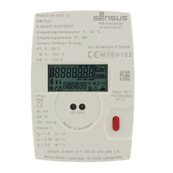
PolluCom ® F/S C Heat/Cooling Meter Installation and Operating Instructions The PolluCom F/S C coaxial meter is used to ® measure energy consumption in systems in which water is used as heating or cooling fluid. The use Items delivered of water with anti-freeze additive is possible with PolluCom F/S C in this case the meter is not MID ®... -
Page 4: Technical Data
PolluCom ® F/S C Heat/Cooling Meter Installation and operating instructions Mechanical class Class M 2 Protection class IP 54 Notes on warranty Battery life for 8 years (with standard device The contents of this manual shall not become part PolluCom ®... -
Page 5: Required Tool
PolluCom ® F/S C Heat/Cooling Meter Installation and Operating Instructions Split version: The calculator is removable and can Where different meter types are installed as part of a system, they must be replaced on a be mounted in a suitable location using the like for like basis to ensure consistent enclosed wall adapter. -
Page 6: Pollucom ® F/S C Ri (Typ Ista)
PolluCom ® F/S C Heat/Cooling Meter Installation and operating instructions 4. Check installation point again for correct flow direction (arrow EAS), correct D2 Sealing eye on the coaxial meter installation of the EAS if necessary. 5. Unscrew the overflow cap (B) from the single- pipe connector (A), remove the profile seal (C1) from the EAS and clean both sealing D3 Sealing eye on EAS (A3) -
Page 7: Pollucom F/S C Rt (Techem Type)
PolluCom ® F/S C Heat/Cooling Meter Installation and Operating Instructions 5.4 PolluCom F/S C RT (Techem type) ® 1. Check installation for completeness. There must be a Techem single-pipe housing in the return and the original installation location(s) for the temperature sensor(s). Caution: In refrigeration systems, the supply is the colder pipe and the return is the warmer pipe. -
Page 8: Pollucom ® F/S C Ra (Allmess Type)
PolluCom ® F/S C Heat/Cooling Meter Installation and operating instructions 8. Check pre-assembled seals (body seal and outlet seal) for correct seating and correct if necessary. 9. Now insert the coaxial meter straight into the monotube housing from above and press it in as far as the bottom. -
Page 9: Installation Directly Into The Heating Or Cooling Medium
PolluCom ® F/S C Heat/Cooling Meter Installation and Operating Instructions 6.1 Installation directly into the heating or Cooling medium Archive level * For new installations, the temperature sensors must be installed directly immersed in accordance with legal regulations. The Sensus MID EAS OEM Service Level set with 3 special ball valves must be used for this, order number:... -
Page 10: Reference Date Level (L 2)
PolluCom ® F/S C Heat/Cooling Meter Installation and operating instructions Reference date Cooling energy (only for consumption for rate 1 hybrid meter version) (if activated) * Reference date External pulse counter consumption of cooling consumption 1* energy (only for hybrid (optional) meter version) Effective date... -
Page 11: Service Level (L 4)
PolluCom ® F/S C Heat/Cooling Meter Installation and Operating Instructions Monthly value Absolute lowest value consumption of external temperature in the warmer pulse counter 1 (optional) pipe incl. date * Monthly value Absolute maximum value consumption of external temperature in the colder pulse counter 2 (optional) pipe incl. -
Page 12: Rate Function Level (L 5)
PolluCom ® F/S C Heat/Cooling Meter Installation and operating instructions Checksum High-resolution energy - Set temperature display * difference - Set temperature limit in the colder pipe High-resolution volume - Set temperature limit in display * the warmer pipe - Set flow limiter - Limit of thermal output Back to the selection menu (if enabled, for limited... -
Page 13: Function Test, Sealing
PolluCom ® F/S C Heat/Cooling Meter Installation and Operating Instructions Reset absolute maximum Enter password * values * Set primary M-Bus Reset error hours * address * Set the secondary M-Bus Back to the selection address * menu (press and hold for 2 seconds) Set customer reference number *... -
Page 14: Optical Interface And Optional Data Transfer
PolluCom ® F/S C Heat/Cooling Meter Installation and operating instructions 10.3 Optional remote reading for heat or cold Example infocode: consumption impulses Code Decryption Pulse value: 1 kWh One or both temperature sensors are Err 2010 short-circuited Closing time: 125 ms Cable break of the temperature sensor Bounce time: none... -
Page 15: Integrated Data Logger
PolluCom ® F/S C Heat/Cooling Meter Installation and Operating Instructions 10.5 Integrated data logger 11. Battery supply The integrated data logger stores the consumption Depending on the version, the PolluCom F/S C is ® values and current values. The logger can record supplied with 1 or 2 lithium batteries (type AA). -
Page 16: Ce Declaration Of Conformity
PolluCom ® F/S C Heat/Cooling Meter Installation and operating instructions 12. CE declaration of conformity M H 1500 INT, Page 16... -
Page 17: Identification And Labeling Of Immersion Sleeves In Existing Systems
PolluCom ® F/S C Heat/Cooling Meter Installation and Operating Instructions 13. Identification and labeling of immersion sleeves in existing systems 13.1 Legal background For the new installation of heat meters with a type approval in accordance with the European Measuring Instruments Directive (MID) up to nominal size q 6 m³, the German calibration law stipulates that the temperature sensors may only be installed directly. -
Page 18: Tolerance List
PolluCom ® F/S C Heat/Cooling Meter Installation and operating instructions 14. Tolerance list Excerpt from the "pronounced acquiescence list of stockpile upsetting sleeves" see PTB: https://www.ptb.de M H 1500 INT, Page 18... -
Page 19: Other Useful Pollucom® F/S C Documents
PolluCom ® F/S C Heat/Cooling Meter Installation and Operating Instructions 15. Other useful PolluCom® F/S C documents M H 1500 INT, Page 19... - Page 20 As of: 0001 – February 24, 2022 Subject to change without notice Sensus GmbH Ludwigshafen Industriestr. 16 D-67063 Ludwigshafen, Germany Phone: + 49 (0) 621 6904-1113 Fax: + 49 (0) 621 6904-1409 Email: info.de.sensus@xylem.com M H 1500 INT, Page 20...
Need help?
Do you have a question about the Sensus PolluCom F/S C and is the answer not in the manual?
Questions and answers