
Related Manuals for EWM M1.83-A-1


Summary of Contents for EWM M1.83-A-1
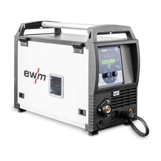
- Page 1 Operating instructions Control M1.83-A-1 099-M183xA-EW501 Observe additional system documents! 15.7.2022...
- Page 2 +49 2680 181-0. A list of authorised sales partners can be found at www.ewm-group.com/en/specialist-dealers. Liability relating to the operation of this equipment is restricted solely to the function of the equipment. No other form of liability, regardless of type, shall be accepted.
-
Page 3: Table Of Contents
Contents Notes on using these operating instructions Contents 1 Contents ............................3 2 For your safety ..........................5 Notes on using these operating instructions ................5 Explanation of icons ....................... 6 Safety instructions ........................7 Transport and installation ....................10 3 Intended use .......................... - Page 4 Contents Notes on using these operating instructions Disposing of equipment ......................38 7 Rectifying faults ..........................39 Software version of the machine control ................39 Error messages (power source) ................... 39 Checklist for rectifying faults ....................40 Dynamic power adjustment ....................41 Resetting welding parameters to the factory settings ............
-
Page 5: For Your Safety
For your safety Notes on using these operating instructions For your safety Notes on using these operating instructions DANGER Working or operating procedures which must be closely observed to prevent imminent serious and even fatal injuries. • Safety notes include the "DANGER" keyword in the heading with a general warning symbol. •... -
Page 6: Explanation Of Icons
For your safety Explanation of icons Explanation of icons Symbol Description Symbol Description Indicates technical aspects which the Activate and release / Tap / Tip user must observe. Switch off machine Release Switch on machine Press and hold Switch Incorrect / Invalid Turn Correct / Valid Numerical value –... -
Page 7: Safety Instructions
For your safety Safety instructions Safety instructions WARNING Risk of accidents due to non-compliance with the safety instructions! Non-compliance with the safety instructions can be fatal! • Carefully read the safety instructions in this manual! • Observe the accident prevention regulations and any regional regulations! •... - Page 8 For your safety Safety instructions WARNING Risk of injury due to improper clothing! During arc welding, radiation, heat and voltage are sources of risk that cannot be avoided. The user has to be equipped with the complete personal protective equipment at all times.
- Page 9 For your safety Safety instructions CAUTION Smoke and gases! Smoke and gases can lead to breathing difficulties and poisoning. In addition, solvent vapour (chlorinated hydrocarbon) may be converted into poisonous phosgene due to the ultraviolet radiation of the arc! • Ensure that there is sufficient fresh air! •...
-
Page 10: Transport And Installation
For your safety Transport and installation CAUTION Obligations of the operator! The respective national directives and laws must be complied with when operating the machine! • Implementation of national legislation relating to framework directive 89/391/EEC on the in- troduction of measures to encourage improvements in the safety and health of workers at work and associated individual guidelines. - Page 11 For your safety Transport and installation CAUTION Risk of accidents due to supply lines! During transport, attached supply lines (mains leads, control cables, etc.) can cause risks, e.g. by causing connected machines to tip over and injure persons! • Disconnect all supply lines before transport! Risk of tipping! There is a risk of the machine tipping over and injuring persons or being damaged itself during movement and set up.
-
Page 12: Intended Use
• Do not improperly modify or convert the equipment! Use and operation solely with the following machines This description may only be applied to machines with the machine control M1.83-A-1 (Picomig puls TKG). Software version The software version of the machine control can be displayed in the machine configuration menu (menu Srv) >... -
Page 13: Part Of The Complete Documentation
Intended use Documents which also apply 3.3.6 Part of the complete documentation This document is part of the complete documentation and valid only in combination with all other parts of these instructions! Read and observe the operating instructions for all system compo- nents, especially the safety instructions! The illustration shows a general example of a welding system. -
Page 14: Machine Description - Quick Overview
Machine description – quick overview Documents which also apply Machine description – quick overview Figure 4-1 Item Symbol Description “Collective interference” signal light “Excess temperature” signal light Welding data display (3-digit) Displays the welding parameters and the corresponding values > see 4.1 chapter Push-button for welding parameter display mode / power-saving mode --------- Welding current --------- Material thickness... - Page 15 Machine description – quick overview Documents which also apply Item Symbol Description Operating mode button ---------- Non-latched -------- Latched ----- Spots ------ Interval Runtime parameters button For selecting the parameters to be set. Also for entering and exiting the menus for ad- vanced settings.
-
Page 16: Welding Data Display
Machine description – quick overview Welding data display Welding data display Figure 4-2 The push-button for the welding parameter display mode is next to the display. Each time the push-button is pressed the display changes to the next parameter. After the last parameter is reached the display continues with the first parameter. -
Page 17: Functional Characteristics
Functional characteristics Gas test – setting the shielding gas volume Functional characteristics Gas test – setting the shielding gas volume If the shielding gas setting is too low or too high, this can introduce air to the weld pool and may cause pores to form. -
Page 18: Welding Task Selection
Functional characteristics MIG/MAG welding 5.2.2 Welding task selection The following steps have to be carried out to select the welding job: • Select basic parameters (material type, wire diameter and shielding gas type) and welding procedures (select and enter JOB number by means of JOB-List > see 8.1 chapter). •... -
Page 19: Welding Type
Functional characteristics MIG/MAG welding 5.2.3 Welding type Different forms of MIG/MAG processes are collectively referred to as welding types. Standard (welding with standard arc) Depending on the set combination of wire feed speed and arc voltage, short arc, transitional arc or spray arc can be used as arc types for welding. -
Page 20: Arc Dynamics (Choke Effect)
Functional characteristics MIG/MAG welding 5.2.4.3 Arc dynamics (choke effect) This function can be used to adjust the arc between a narrow, hard arc with deep penetration (positive values) and a wide and soft arc (negative values). Figure 5-6 5.2.5 Operating modes (functional sequences) 5.2.5.1 Explanation of signs and functions Symbol... - Page 21 Functional characteristics MIG/MAG welding Non-latched mode Figure 5-7 Step 1 • Press and hold torch trigger. • Shielding gas is expelled (gas pre-flows). • Wire feed motor runs at “creep speed”. • Arc ignites after the wire electrode makes contact with the workpiece; welding current flows. •...
- Page 22 Functional characteristics MIG/MAG welding Special, non-latched The activation or setting of this operating mode is described in the chapter Program se- quence > see 5.2.6 chapter. Figure 5-8 Step 1 • Press and hold torch trigger • Shielding gas is expelled (gas pre-flows) •...
- Page 23 Functional characteristics MIG/MAG welding Latched mode Figure 5-9 1. cycle • Press and hold torch trigger • Shielding gas is expelled (gas pre-flows) • Wire feed motor runs at “creep speed” • Arc ignites when the wire electrode makes contact with the workpiece Welding current flows •...
- Page 24 Functional characteristics MIG/MAG welding Latched special The activation or setting of this operating mode is described in the chapter Program se- quence > see 5.2.6 chapter. Figure 5-10 1st cycle • Press and hold torch trigger. • Shielding gas is flowing (gas pre-flow). •...
- Page 25 Functional characteristics MIG/MAG welding Spot welding Figure 5-11 Start • Press and hold torch trigger. • Shielding gas is expelled (gas pre-flows). • Arc ignites after the wire electrode makes contact with the workpiece at creep speed. • Welding current flows. •...
-
Page 26: Program Sequence
Functional characteristics MIG/MAG welding Interval Figure 5-12 Start • Press and hold torch trigger. • Shielding gas is expelled (gas pre-flows). Sequence • Arc ignites after the wire electrode makes contact with the workpiece at creep speed. • Welding current flows. •... -
Page 27: Expert Menu (Mig/Mag)
Functional characteristics MIG/MAG welding Display Setting/selection Main program End program Start current (as percentage, dependent on main current) Start time (duration of start current) Slope time of start program P to main program P START Slope time of main program P to end program P End current (as a percentage, dependent on main current) End current time (duration of end current) -
Page 28: Conventional Mig/Mag Welding (Gmaw Non Synergic)
Functional characteristics MMA welding Display Setting/selection Slope time of main program P to end program P End current (as a percentage, dependent on main current) End current time (duration of end current) Burn-back correction 5.2.8 Conventional MIG/MAG Welding (GMAW non synergic) You can only change the JOB number when no welding current is flowing. -
Page 29: Hotstart
Functional characteristics MMA welding 5.3.3 Hotstart The function hot start ensures a secure igniting of the arc and a sufficient heating to the still cold parent metal at the beginning of the welding process. The ignition takes place here with increased current (hot start current) over a certain time (hot start time). -
Page 30: Tig Welding
Functional characteristics TIG welding TIG welding 5.4.1 Welding task selection • Select TIG JOB 127. You can only change the JOB number when no welding current is flowing. Figure 5-21 5.4.2 Adjusting the gas post-flow time • Preselection: Select TIG JOB 127 > see 5.4.1 chapter. Figure 5-22 Display Setting/selection... -
Page 31: Expert Menu (Tig)
Functional characteristics TIG welding 5.4.3 Expert menu (TIG) The Expert menu has adjustable parameters stored that don’t require regular setting. The number of pa- rameters shown may be limited, e.g. if a function is deactivated. Figure 5-23 Display Setting/selection Gas pre-flow time Start current (as percentage, dependent on main current) Upslope time to main current Downslope time... -
Page 32: Operating Modes (Functional Sequences)
Functional characteristics TIG welding 5.4.5 Operating modes (functional sequences) 5.4.6 Legend Symbol Meaning Press torch trigger Release torch trigger Welding current Gas pre-flows Gas post-flows Non-latched Latched Time Upslope time Downslope time Down Start current start End-crater current 5.4.6.1 Automatic cut-out Once the fault periods have elapsed, the automatic cut-out stops the welding process when it has been triggered by one of two states: •... - Page 33 Functional characteristics TIG welding Non-latched mode Figure 5-25 1st cycle • Press and hold torch trigger. • Shielding gas is expelled (gas pre-flows). The arc is ignited using liftarc. • The welding current flows with the value set for the starting current I start •...
- Page 34 Functional characteristics TIG welding Latched mode Figure 5-26 1st cycle • Press and hold torch trigger. • Shielding gas is expelled (gas pre-flows). The arc is ignited using liftarc. • The welding current flows with the value set for the starting current I start 2nd cycle •...
-
Page 35: Machine Configuration Menu
Functional characteristics Machine configuration menu Machine configuration menu 5.5.1 Selecting, changing and saving parameters Figure 5-27 Display Setting/selection Calibration The machine will be calibrated for approx 2 seconds each time it is switched on. Exit the menu Exit Machine configuration Settings for machine functions and parameter display Dynamic power adjustment >... -
Page 36: Power-Saving Mode (Standby)
Functional characteristics Power-saving mode (Standby) Power-saving mode (Standby) You can activate the power-saving mode by either pressing the push-button > see 4 chapter for a pro- longed time or by setting a parameter in the machine configuration menu (time-controlled power-saving mode ) >... -
Page 37: Maintenance, Care And Disposal
Maintenance, care and disposal General Maintenance, care and disposal General DANGER Risk of injury due to electrical voltage after switching off! Working on an open machine can lead to fatal injuries! Capacitors are loaded with electrical voltage during operation. Voltage remains present for up to four minutes after the mains plug is removed. -
Page 38: Disposing Of Equipment
Information on returning used equipment or collections can be obtained from the respective municipal administration office. Devices can also be returned to EWM sales partners across Europe. Further information on the topic of the disposal of electrical and electronic equipment can be found on our website at: https://www.ewm-group.com/de/nachhaltigkeit.html. -
Page 39: Rectifying Faults
Rectifying faults Software version of the machine control Rectifying faults All products are subject to rigorous production checks and final checks. If, despite this, something fails to work at any time, please check the product using the following flowchart. If none of the fault rectification procedures described leads to the correct functioning of the product, please inform your authorised dealer. -
Page 40: Checklist For Rectifying Faults
Rectifying faults Checklist for rectifying faults Error message Possible cause Remedy Electronics error Switch the machine off and on again. If the error persists, notify service department Temperature error Allow the machine to cool down Motor fault Check wire feed mechanism, switch the machine off and on again, inform the service department if the fault persists. -
Page 41: Dynamic Power Adjustment
Rectifying faults Dynamic power adjustment Functional errors Mains fuse triggers - unsuitable mains fuse Set up recommended mains fuse. Machine does not start up after switching on (device fan and possibly coolant pump have no function). Connect the control cable of the wire feeder. -
Page 42: Resetting Welding Parameters To The Factory Settings
Rectifying faults Resetting welding parameters to the factory settings Resetting welding parameters to the factory settings All customised welding parameters that are stored will be replaced by the factory settings. RESET Figure 7-1 Display Setting/selection Calibration The machine will be calibrated for approx 2 seconds each time it is switched on. Initialising Keep the push-button pressed until is shown on the display. -
Page 43: Appendix
Appendix JOB-List Appendix JOB-List Machine version Picomig puls: MIG/MAG pulse arc welding can be selected for the JOBs 6-8, 34, 35, 74-76, 82-84, 90-92, 110-112, 114-116, 177, 178, 233 and 236-238. If an attempt is made to set another JOB to pulse, “noP” = “no Puls”... -
Page 44: Parameter Overview - Setting Ranges
Appendix Parameter overview – setting ranges Parameter overview – setting ranges Parameter / function Setting range MIG/MAG Gas pre-flow time 20,0 Start current (percentage of main current) Ignition current time 20,0 Slope time (duration from start current to main current) 20,0 Slope time (duration from main current to end current) 20,0... -
Page 45: Searching For A Dealer
Appendix Searching for a dealer Searching for a dealer Sales & service partners www.ewm-group.com/en/specialist-dealers "More than 400 EWM sales partners worldwide" 099-M183xA-EW501 15.7.2022...
Need help?
Do you have a question about the M1.83-A-1 and is the answer not in the manual?
Questions and answers