Table of Contents
Advertisement
Quick Links
取扱説明書
高電圧テスト プローブ
HP11-TOS
本製品は、当社の絶縁抵抗試験器
のプローブです。 操作性に優れた扱いやすい形状で、 被試験物への配線時間の短
縮が可能です。
テス トプロ ーブを 使用し た絶縁 抵抗試 験では、被 試験物 など高 電圧充 電部(
ページの解説
*1
注 記
・本製品は当社の絶縁抵抗試験器
とを目的に設計されています。 ご使用になる前に、
明書に記載されている警告および注意事項をよくお読みください。
・本テストプローブを使用するには、 バージョン
搭載した
•
本 テスト プロー ブは、本製品 だけで は避け られない 感電の 可能性 がありま
す。被試験物、 作業台、および周辺の作業環境の安全性を確保してください。
•
作業者が日本語を理解できない場合には、取扱説明書を適切な言語に翻訳し
てください。
•
作 業者が この取扱 説明書 の内容を 理解して から作 業にあた れるよ うに指導
してください。
•
こ の取扱 説明書は 作業者 がいつで も読める ように 本製品の 近くに 備えてく
ださい。
次の操 作によ って感電 して、人命に かかわ る重大な 事故にな ること がありま
す。
•
接触ピンに触れる。
•
試験中の被試験物に触れる。
次の操作には、感電する可能性があります。感電した場合には、人命にかかわ
る重大な事故になることがあります。
•
作業台などにひじをついて試験をする。
•
試験のため以外に電圧を発生させる。
参照)に近づいて操作することによる感電の危険があります。
が必要です。
TOS7200
作業管理者へのお願い
危険な操作
T OS7200
に接続して使用する試験電圧出力用
TOS7200
Part No. Z1-003-500, IA003641
Dec. 2005
と組み合わせて使用するこ
TOS7200
1.07
以降の
8
の取扱説
ROM
を
Advertisement
Table of Contents

Related Manuals for Kikusui HP11-TOS


Summary of Contents for Kikusui HP11-TOS
- Page 1 Part No. Z1-003-500, IA003641 取扱説明書 Dec. 2005 高電圧テスト プローブ HP11-TOS 本製品は、当社の絶縁抵抗試験器 T OS7200 に接続して使用する試験電圧出力用 のプローブです。 操作性に優れた扱いやすい形状で、 被試験物への配線時間の短 縮が可能です。 テス トプロ ーブを 使用し た絶縁 抵抗試 験では、被 試験物 など高 電圧充 電部( ページの解説 参照)に近づいて操作することによる感電の危険があります。 注 記 ・本製品は当社の絶縁抵抗試験器 TOS7200 と組み合わせて使用するこ とを目的に設計されています。 ご使用になる前に、 TOS7200 の取扱説...
- Page 2 ・ 高電圧遮断後、すぐに接触ピンを被試験物から離してしまうと、被試験物が 強制的に放電されず危険です。 ■ リモートコントロールケーブルは必ず接続してください。 ・ リモートコントロールケーブルを接続しないで試験器側の スイッチ START で試験を実行しないでください。感電の可能性があります。 ■ 他の絶縁抵抗試験器では使用できません。 ・ 本テストプローブは当社の絶縁抵抗試験器 TOS7200 用です。コネクタが適 合しても、他の絶縁抵抗試験には使用できません。 ■ 最大使用電圧は 1 000 Vdc です。 1 000 Vdc ・ 本テストプローブの最大使用電圧( ページの解説 参照)は で す。最大使用電圧を超えて使用すると感電の可能性があります。 ■ テストプローブを振り回さないでください。 ■ テストプローブのケーブルを引っ張ったり、体に巻き付たりしないでくださ い。 HP11-TOS...
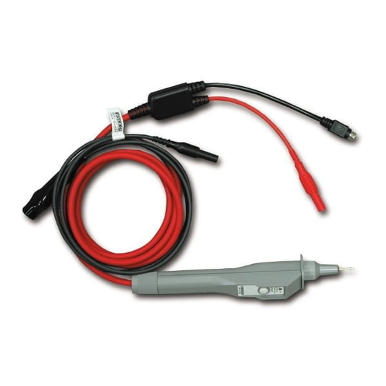
- Page 3 触れると感電します。 HV LED が点灯しているときに、絶対 にこの部分には触れないでください。 接触ピン 高電圧が出力されるピンです。 被試験物のテストポイントに接触 させて使います。 ホルダ 高電圧の出力される接触ピン を保持している部分です。 ST AR T スイッチ 試験を開始します。 HV LED 試験中はこのスイッチを押し続けて 接触ピンに高電圧が印加されて ください。指を放すと試験は強制的 いることを示す赤色 です。 に中断します。 この は試験器側の D ANGER ランプと同時に点灯 (または消灯)します。 リモートコントロール ケーブル(黒色) 高電圧側ケーブル (赤色) 低電圧側テストリード (黒色) HP11-TOS...
- Page 4 ホル ダを 時計 方向 いっぱ いに 回し ま す。 ピンが正しく装着されている状態 故障時は使用中止 PO WER 次のような場合は故障です。 危険なため、 すぐに試験器の スイッチをオ フにして、使用を中止してください。 HV LED ・ が点灯しない。 ・ HV LED の点灯の仕方が、試験器の DANGER ランプの点灯の仕方と一致し ていない。 START HV LED ・ スイッチから指を離しても、 が消えない。 警告 ・修理が完了するまで、他の人が使用できないように管理してください。 ・危険ですので修理は必ず購入先または当社営業所に依頼してください。 HP11-TOS...
- Page 5 LO W 端子へ挿入します。 リモートコントロールケーブルを試験器の REMO TE 端子へ接続します。 高電圧側ケーブルを試験器の 端子へ接続します。 HIGH T OS7200 HIGH 端子へ REMO TE 端子へ LO W 端子へ リモートコントロールケーブルの接続によって、 試験の開始、 中断は次のような 操作になります。 試験器のパネル操作 テストプローブの操作 試験の開始 無効 ST AR T スイッチを押す。 ST OP スイッチを押す。 ST AR T スイッチから指を放す。 試験の中断 HP11-TOS...
- Page 6 に設定することをお勧めします。 ・ 「絶縁抵抗試験器への接続」に従ってテストプローブを試験器へ接続します。 低電圧側テストリー ドのワニグチクリッ プを被試験物の低電 圧側ポイント へ接続します。 被試験物のテスト ポイント(高電圧側ポ イント)にテストプロ ーブの接触 ピンを当てます。 ST AR T スイッチを押します。 HV LED が点灯して、試験電圧が接触ピンに出力されます。 試験中は接触ピンを被試験物から離さないでください。 試験終了後、 スイッチから指を放します。 ST AR T まだ、接触ピンを被試験物から離さないでください。 HV LED が消えていることを確認します。 テストプローブを被試験物から離します。 低電圧側テストリードを被試験物から外します。 すべての試験終了後、試験器の PO WER スイッチをオフにしてください。 HP11-TOS...
- Page 7 ・ 試験を中断するには、 ST AR T スイッチか ら指を放します。 ・ HV LED の消灯を確認してから、 接触ピン をテストポイントから離してください。 テストポイントへ 被試験物 低電圧側ポイントへ 保守 長期間にわたって本製品の初期性能を保つためには、 定期的に保守、 点検が必要 です。 ・ 必ず試験器からテストブローブを取り外してお手入れしてください。 ・ シンナーやベンジンなど揮発性のものは使用しないでください。 表面の変色、 印刷文字の消失などを起こすことがあります。 クリーニング テストプローブが汚れた場合には、水で 薄めた中性洗剤を柔らかい布につけて、 軽く拭いてください。 定期点検 テストプローブのケーブル、接触ピン、低 電圧側テストリードは消耗品です。 年に 度の周期で当社サービス技術者による点検をお勧めします。 点検は購入先 または当社営業所にご依頼ください。 HP11-TOS...
- Page 8 り扱い可能な電圧 電流の最大値を示します。 保 証 この製品は、菊水電子工業株式会社の厳密な試験 • 検査を経て、その性能は規格を満足して いることが確認され、お届けされております。 弊社製品は、お買上げ日より 年間に発生した故障については、無償で修理いたします。 但し、次の場合には有償で修理させていただきます。 取扱説明書に対して誤ったご使用およびご使用上の不注意による故障、損傷。 不適当な改造・調整・修理による故障および損傷。 天災・火災・その他外部要因による故障および損傷。 なお、この保証は日本国内に限り有効です。 This w arr anty is v alid only in J apan. 菊水電子工業株式会社 本社 技術センター 〒 横浜市都筑区東山田 • 224-0023 1-1-3 (代) TEL : 045-593-0200 http://www .kikusui.co.jp/ HP11-TOS...
-
Page 9: High Voltage Test Probe
The HP11-T OS High V oltage T est Probe is a test v oltage output probe that connects to a KIKUSUI T OS7200 Insulation Resistance T ester . Its con v enient shape allo ws f aster connection to the de vice under test (DUT). -
Page 10: Precautions For Use
Ne ver use the test pr obe with other insulation resistance tester s. • The test probe is designed specifi cally f or use with a KIKUSUI T OS7200 Insu - lation Resistance T ester . It cannot be used with other insulation resistance testers , e v en if the connector appears to be compatib le . -
Page 11: Component Names And Functions
D ANGER lamp of the T ester . Remote Contr ol Cab le (b lac k) High V olta g e Cab le (red) Lo w V olta g e Side T est Lead wire (b lac k) HP11-TOS... -
Page 12: Inspection Bef Ore Star Ting
• Implement measures so that no one can use the test probe until it has been repaired. • T o minimiz e potential hazards , alw a ys contact y our Kikusui distr ib - utor or agent f or repairs . - Page 13 Connecting the remote control cable starts or stops testing as indicated below: Tester’s Panel Operation Operation of Test Probe Starting test Disabled Depress the START switch. Stopping test Press the STOP switch. Release your finger from the START switch. HP11-TOS...
-
Page 14: Test Procedure
Confirm that the HV LED is not lit. Remove the test probe from the DUT. Disconnect the alligator clip of the low voltage side test leadwire from the DUT. After completing all tests, turn off the POWER switch of the Tester. HP11-TOS... -
Page 15: Maintenance
Periodic Inspection The cable of the test probe, contact pin, and low voltage side test leadwire are consumables. We recommend an annual inspection by one of service engineers. To have an inspection performed, contact your Kikusui distributor or agent. HP11-TOS... -
Page 16: Specifications
*2: The rated maximum voltage/current refers to the maximum voltage/ current the test probe is capable of handling within the given operating temperature and humidity ranges. KIKUSUI ELECTRONICS CORP. 1-1-3, Higashiyamata, Tsuzuki-ku, Yokohama, 224-0023, Japan Tel: +81-45-593-7570 Fax: +81-45-593-7571 http://www.kikusui.co.jp/...
Need help?
Do you have a question about the HP11-TOS and is the answer not in the manual?
Questions and answers