Table of Contents
Advertisement
Quick Links
User's Manual
Electrical Safety Analyzer
TOS93 Series
TOS9300
TOS9301
TOS9302
TOS9303
TOS9303LC
DANGER
This product generates high voltage!
Improper operation can lead to serious accidents.
To prevent accidents, be sure to read the section
"Safety Precautions for Testing" in this manual.
Keep this manual close to the product so that the operators
can read the manual at any time.
Part No. IB032282
Dec 2018
Withstanding Voltage and Insulation
Protective Conductor Current Test 126
Component Names 12
Safety Precautions for Testing 18
Basic Operation 42
Resistance Tests 49
Earth Continuity Test 85
Touch Current Test 102
Patient Leakage Current Test 145
External Control 199
Memory Function 213
System Settings 219
Maintenance 239
Specifications 245
Contents 7
Installation 24
Meter Mode 168
Auto Test 182
Appendix 269
Advertisement
Table of Contents

Related Manuals for Kikusui TOS9300


Summary of Contents for Kikusui TOS9300
- Page 1 Safety Precautions for Testing 18 Installation 24 User’s Manual Basic Operation 42 Electrical Safety Analyzer Withstanding Voltage and Insulation TOS93 Series Resistance Tests 49 TOS9300 Earth Continuity Test 85 TOS9301 Touch Current Test 102 TOS9302 Protective Conductor Current Test 126 TOS9303 TOS9303LC...
- Page 2 Testing is not possible upon opening the package When you first turn on this product after opening the package, the safety interlock will prevent you from performing tests. Connect the included SIGNAL I/O plug to the SIGNAL I/O connector to temporarily release the interlock 204).
-
Page 3: About Manuals
It also explains how to configure it, oper- © Copyright 2018 Kikusui Electronics Corporation ate it, perform maintenance on it, and so on. Read this manual thoroughly before use, and use the product prop- erly. -
Page 4: Accessories
Failure analysis that were not possible with pre- vious Kikusui withstanding voltage testers is now possi- ble. Support for AC/DC earth continuity test up to 40 A... -
Page 5: Notations Used In This Manual
• You will receive a potentially fatal electric shock if: • You touch an output terminal while output is being generated. • In this manual, the TOS9300, TOS9301, TOS9302, TOS9303, and TOS9303LC electrical safety analyzer • You touch a test lead that is connected to an output are also referred to as the TOS93 series. -
Page 6: Notes On Usage
TOS9300, TOS9301 Notes on Usage Air outlet Air inlet • When installing this product, be sure to observe the tem- perature and humidity ranges indicated below. Operating temperature range: 0 °C to 40 °C (32 °F to 104 °F) Operating humidity range: 20 %rh to 80 %rh (no con-... -
Page 7: Table Of Contents
Contents About Manuals ...........3 Connecting the test leads........40 Accessories ............4 Product Overview ..........4 Basic Operation Notations Used in This Manual......5 Safety Precautions ..........5 Basic Panel Operations........42 Notes on Usage..........6 Switching menus ..........42 Component Names ..........12 Using the function keys ........43 Inputting numbers and characters...... - Page 8 Starting a Test ..........77 Judgment delay (Judge Delay) ......111 Test time .............112 Output time limit ............77 Measurement range..........113 Starting a test ............78 Measurement mode (Measure Mode)....115 Operation after a test starts........79 Voltmeter band expansion (VoltMeter BandWidth)... Changing the voltage setting during a test ....82 Finishing the Test and Viewing the Judgment.
- Page 9 Connecting the test leads........179 Patient Leakage Current Taking measurements........179 Test Measurement operation ........180 Measurement example (judgment of the parts that can be touched)..........180 Setting Test Conditions ........145 Displaying the setup screen (Home menu) ..145 Description of test conditions......146 Auto Test Network ..............
- Page 10 Starting and Stopping Tests ......207 Initializing the Settings........235 Starting a test ............207 Restoring the factory default settings....235 Stopping a test ............207 Restoring the reset settings ........236 Monitoring the Test Status......208 Updating ............237 Monitoring the test mode........208 Displaying the Device Information....238 Monitoring the test and voltage generation status ..
- Page 11 Remote control box ..........281 DIN adapter cable..........281 High voltage test probe........282 Warning light unit..........282 Multi-outlet ............283 Brackets.............. 284 Troubleshooting..........285 Index...............287 User’s Manual TOS93 Series...
-
Page 12: Component Names
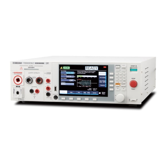
Component Names Front panel TOS9300, TOS9301 TOS9302, TOS9303 TOS9303LC 4 5 6 User’s Manual TOS93 Series... - Page 13 No. Name Function DANGER LED Lights red when the power is turned on, when a test is in progress, when – a high voltage is being output, or when there is residual voltage at the output terminals. On the TOS9303LC, the LED also lights red when sup- ply voltage is being supplied to the EUT.
- Page 14 Controls HOME/FUNC AUTO MEMORY SYSTEM CLEAR ESCAPE ENTER LOCAL KEY LOCK No. Name Function Display Displays the settings, measured values, and other information. p.15 Menu keys Switch the display. p.42 HOME/FUNC key Switches between the test setup screen (Home menu) and test selection p.42 screen (Function menu).
- Page 15 Display No. Name Function Test mode Selected test type. – Test status. – – READY Ready to start test. – RISE Voltage or current rising. – FALL Voltage or current falling. – TEST Testing. – PASS Test successful. – U-FAIL Test failed because a value greater than or equal to the upper limit was detected.
- Page 16 Rear panel TOS9300, TOS9301 1 2 3 TOS9302, TOS9303 1 2 3 TOS9303LC 1 2 3 User’s Manual TOS93 Series...
- Page 17 Name Function STATUS OUT connector Connect option products. p.212 SCANNER connector Connect to the high voltage scanner option. p.280 USB port USB port for remote control. LAN port LAN port for remote control. Interface RS232C port RS232C port for remote control. Manual DC OUT 5 V terminal Connect option products.
-
Page 18: Safety Precautions For Testing
• When supply voltage is being supplied to the EUT (TOS9303LC only) Check whether the DANGER LED lights at power on. If it does not, stop using the product, and contact your Kikusui agent or distributor. Test Precautions Pre-test precautions WARNING Risk of electric shock. -
Page 19: Testing Precautions
Never touch these while the DANGER LED is lit. • When performing a withstanding voltage test, be sure to wear rubber gloves for electrical work. If obtaining these gloves is difficult, contact your Kikusui agent or distributor. During testing, the DANGER LED lights, and the display shows “TEST.” Be careful because high voltage may be being output when the DANGER LED is lit. -
Page 20: Precautions After Output Has Been Turned Off20
Safety Precautions for Testing Precautions after Output Has Been Turned Off Risk of electric shock. WARNING • For a while after the output has been turned off, do not touch the items that have been charged to a high voltage, such as the EUT, the test leads, the test probes, and the areas near the output terminals. -
Page 21: Remote Control Precautions
If the tester is not operating properly, it may be generating a high voltage irrespective of the settings made by the operator. Immediately turn the POWER switch off, and disconnect the power cord from the outlet. Stop using the product immediately, and contact your Kikusui agent or distributor. Emergency measures There are two actions that you must carry out if, due to a malfunction in the product or the EUT, there is a possibility of an emergency occurring such as electric shock or damage to the EUT. -
Page 22: Protection Functions
Disable and pressing STOP releases the PROTECTION mode, but the product needs to be calibrated. To have your product cali- brated, contact your Kikusui agent or distributor. Remote The REMOTE connector is connected or discon- Check the REMOTE connector, and nected. - Page 23 Remedy Communication An internal communication error is occurring. Repair is necessary. Turn the power off, and contact your Kikusui agent or distributor. No SCPI communication took place for more Check the SCPI communication sta- than the specified time when the watchdog tus.
-
Page 24: Installation
If the supplied power cord cannot be used because the rated voltage or the plug shape is incompatible, have a qualified engineer replace it with an appropriate power cord that is 3 m or less in length. If obtaining a power cord is difficult, contact your Kikusui agent or dis- tributor. -
Page 25: Checking Whether The Power Is On Or Off
Installation Checking Whether the Power Is On or Off Checking the interlock operation When this product is turned on for the first time after purchase, it starts in PROTECTION mode in which the interlock function (p.204) prevents tests from being executed. Check that the interlock is working prop- erly. -
Page 26: Turning The Power On
Turn the POWER switch ( ) on. The DANGER LED lights, but no voltage is generated. If it does not, stop using the product, and contact your Kikusui agent or distributor. POWER switch After the startup screen is displayed, the home screen of the test that was in use before the power was turned off the last time appears. -
Page 27: Turning The Power Off
Installation | Checking Whether the Power Is On or Off Turning the power off Turning the POWER switch off ( ) The power is turned off. WARNING Risk of electric shock. • If you want to turn the POWER switch back on, wait at least 10 seconds. It is dan- gerous to do otherwise, because the protective functions of the product may not work effectively. -
Page 28: Connection For Withstanding Voltage And Insulation Resistance Tests
Installation Connection for Withstanding Voltage and Insulation Resistance Tests Applicable models for withstanding voltage test: All models Applicable models for insulation resistance test: 9300 9301 9303 9303LC WARNING Risk of electric shock. While the DANGER LED is lit, never touch the HIGH VOLTAGE terminal, test leads, or EUT. - Page 29 Installation | Connection for Withstanding Voltage and Insulation Resistance Tests Check that the POWER switch is off and that the DANGER LED is off. Raise the LOW terminal’s cable lock, and then connect the low-voltage test lead (black). Lower the cable lock. Check that the connection is secure.
- Page 30 Installation | Connection for Withstanding Voltage and Insulation Resistance Tests Examples of how to connect test leads to the EUT Ex: Between the power supply Ex: Between the power supply Ex: Between the insulation (primary) and grounded (primary) and ungrounded connection area and enclosure enclosure...
- Page 31 Installation | Connection for Withstanding Voltage and Insulation Resistance Tests Stabilizing measurements If measurements are unstable due to the effect of noise, such as when making highly sensitive measure- ments, using a shield box can stabilize the measurements.When using a shield box, set Grounding mode (GND) (p.66) to Guard and connect the shield box’s chassis connection wire to the GUARD terminal on...
-
Page 32: Removing The Test Leads
Installation | Connection for Withstanding Voltage and Insulation Resistance Tests Removing the test leads This section explains how to remove a test lead that is already connected to the EUT using the TOS9303LC as an example. Check that the DANGER LED is turned off. Disconnect the high-voltage test lead (red) from the front-panel HIGH VOLTAGE ter- minal. -
Page 33: Connection For Earth Continuity Tests
After making the connections, set the test conditions by referring to “Terminal wiring method (Terminals Wire)” (p.92). If you use test leads other than those supplied with the product, the product specifications may not be met. Contact your Kikusui agent or distributor for details. EARTH CONTINUITY EARTH CONTINUITY... -
Page 34: Connecting The Test Leads
Connect the supplied test leads for earth continuity testing (TL13-TOS) to the product. If you use test leads other than those supplied with the product, the product specifications may not be met. Contact your Kikusui agent or distributor for details. Connection example... - Page 35 Installation | Connection for Earth Continuity Tests Connect the test lead’s current output cable (red) to the EARTH CONTINUITY OUT- PUT HI terminal and the voltage measurement cable (red) to the SENSING HI termi- nal. Power output cable (red) Voltage measurement cable (red) This completes the connections.
-
Page 36: Removing The Test Leads
Installation | Connection for Earth Continuity Tests Removing the test leads You can remove the HI and LO test leads in any order. Check that the DANGER LED is turned off before removing the test leads. To remove the test leads from the OUTPUT HI and LO terminals, push the plugs in once and then pull the terminals out. -
Page 37: Connection For Leakage Current Tests
Installation Connection for Leakage Current Tests Applicable models: 9303LC Using the insulation transformer Some standards recommend an insulation transformer to be used in leakage current tests. If unexpected current flows during a test due to a an EUT malfunction or the like, other devices in the same facility may shut down as a result of the earth leakage circuit breaker tripping. - Page 38 Installation | Connection for Leakage Current Tests Insulation transformer After the test leads are connected Check that Line OUT (p.242) is set to OFF. Connect the EUT’s power cord to the AC LINE OUT terminal block on the rear panel. Attach crimping terminals that match the terminal block screws (M4) to the EUT’s power cord.
- Page 39 Installation | Connection for Leakage Current Tests Connect the insulation transformer plug to the power supply that can output the EUT’s rated voltage. This completes the connections. When not using the AC LINE OUT terminal block Even when you are not using the terminal block, attach the terminal cover so that the terminals are not exposed.
-
Page 40: Connecting The Test Leads
Installation | Connection for Leakage Current Tests Connecting the test leads WARNING Risk of electric shock. When using the test leads, do not touch the tip of the lead with your hand. When performing a touch current (TC) test or patient leakage current (Patient) test, you will use the sup- plied test leads for leakage current testing (TL22-TOS). - Page 41 Installation | Connection for Leakage Current Tests Using the flat probe In the touch current test, to measure the touch current when the enclosure of the EUT is touched with the palm of your hand, use the supplied flat probe (FP01-TOS). The size of the metal foil of the FP01-TOS (10 cm ×...
-
Page 42: Basic Operation
Basic Operation Basic Panel Operations Switching menus The following menus are available. To switch between menus, press the Menu key. Home Menu: Set the conditions of each test. Execute tests. Function Menu: Display a summary of settings of each test. Switch test modes. Memory Menu: Use the memory function. -
Page 43: Using The Function Keys
Basic Operation | Basic Panel Operations Using the function keys On the display, the available functions are shown in the function area and sub-function area. You can exe- cute or select the functions by pressing the corresponding function key or sub-function key. The selected function is shown with a light gray background. - Page 44 Basic Operation | Basic Panel Operations Key names Individual function keys and sub-function keys are distinguished by indicating the function names shown in the function area or sub-function area as the key names. Described as the Time key Operation example (enabling the editing of the interface settings) Press SYSTEM >...
-
Page 45: Inputting Numbers And Characters
Basic Operation | Basic Panel Operations Inputting numbers and characters You can enter numbers and characters in input areas from the front panel or external keyboard. Number input and character input switch automatically according to the input area. If numbers or characters are selected in an input area, they can be changed. If only a cursor is shown in an input area, you can enter characters or numbers at the cursor position. -
Page 46: Changing Values
Basic Operation | Basic Panel Operations Changing values To change the test voltage or other values, use the numeric keypad or the rotary knob. If you enter a value with the numeric keypad, following input, press the ENTER key to confirm the value. Use the numeric keypad or the rotary knob to change the value. -
Page 47: Selecting The Test Mode
(IR) component has enough resistance for the voltage to be handled. There is a 7200 V test and a -1000 V test (-1000 V test only on the TOS9300). Earth continuity (EC) This test evaluates the continuity of the protective connection of devices (Class I devices) that are designed to ensure safety with basic insulation and protective earth grounding. -
Page 48: Selecting The Test Mode
Basic Operation | Selecting the Test Mode Selecting the test mode Select the test mode on the Function menu screen. The tests that can be selected varies depending on the model. On the Home menu screen, press HOME/FUNC. Example: Home menu screen of ACW The Function menu screen appears. -
Page 49: Withstanding Voltage And Insulation Resistance Tests
On the Function menu screen (p.42), press ACW, DCW, or IR. If you press IR, select the voltage range with the sub-function keys (7200 V or -1000 V) (excluding the TOS9300). The setup screen (Home menu) for the ACW, DCW, or IR test conditions appears. -
Page 50: Description Of Test Conditions
Withstanding Voltage and Insulation Resistance Tests | Setting Test Conditions Description of test conditions The test conditions you can set vary for ACW, DCW, and IR. The following test conditions with a check mark can be used with the corresponding test. ACW DCW IR Test condition Description... -
Page 51: Test Voltage
Withstanding Voltage and Insulation Resistance Tests | Setting Test Conditions Test voltage Set the voltage to apply to the EUT. You cannot specify a voltage that exceeds the limit voltage (p.52). On the Home menu screen, press Voltage > Test Voltage. Example: Home menu screen of ACW Use the numeric keypad or the rotary knob to enter the voltage. -
Page 52: Limit Voltage
Withstanding Voltage and Insulation Resistance Tests | Setting Test Conditions Limit voltage Set the upper limit of the voltage to apply to the EUT. This prevents unnecessarily high voltage from being applied to the EUT by mistake. On the Home menu screen, press Voltage > Limit Voltage. Example: Home menu screen of ACW Use the numeric keypad or the rotary knob to enter the voltage. -
Page 53: Start Voltage
Withstanding Voltage and Insulation Resistance Tests | Setting Test Conditions Start voltage Set the voltage 0.1 seconds after the START switch is pressed as a percentage of the test voltage. If you do not want to set the start voltage, set Start Voltage to off. Test status READY RISE... -
Page 54: Frequency
Withstanding Voltage and Insulation Resistance Tests | Setting Test Conditions Frequency This can be set only for AC withstanding voltage (ACW) tests. Set the test voltage frequency to 50 Hz or 60 Hz. appears during testing according to the set- ting. -
Page 55: Upper Limit
Withstanding Voltage and Insulation Resistance Tests | Setting Test Conditions Upper limit Set the reference current or resistance for upper limit judgment. If current greater than or equal to Upper is measured, upper limit judgment (U-FAIL) results. In insulation resistance (IR) tests, you can set Upper to off if upper limit judgment is not necessary. -
Page 56: Lower Limit
Withstanding Voltage and Insulation Resistance Tests | Setting Test Conditions Lower limit Set the reference current or resistance for lower limit judgment. If current less than or equal to Lower is measured after the voltage reaches the test voltage, lower limit judgment (L-FAIL) results. To disable lower limit judgment, set Lower to off. -
Page 57: Unit Of Criteria (Judge Type)
Withstanding Voltage and Insulation Resistance Tests | Setting Test Conditions Unit of criteria (Judge Type) Set the unit of the upper limit (p.55) or lower limit (p.56) for insulation resistance (IR) tests to resistance or current. On the Home menu screen, press Judgement > Judge Type. If the Judge Type key is not displayed, press Upper or Lower to display it. -
Page 58: Auto Setting Of The Judgment Delay (Delay Auto)
Withstanding Voltage and Insulation Resistance Tests | Setting Test Conditions Auto setting of the judgment delay (Delay Auto) This can be set only in DC withstanding voltage (DCW) and insulation resistance (IR) tests. When the test voltage is applied to an EUT with a capacitive component, a large charge current may flow until charging is completed. - Page 59 Withstanding Voltage and Insulation Resistance Tests | Setting Test Conditions On the Home menu screen, press Judgement > Delay Auto. Example: Home menu screen of IR Press Delay Auto to switch between ON and OFF. Delay Auto switches between on and off each time you press the key. If you select off, use the numeric keypad or the rotary knob to enter the time.
-
Page 60: Test Time
Withstanding Voltage and Insulation Resistance Tests | Setting Test Conditions Test time Set the test time to on or off. Value Description Set the time from when the Voltage rise time (p.61) has passed to the end of the test. If upper limit judgment (U-FAIL) or lower limit judgment (L-FAIL) does not occur during a test, the test will result in PASS. -
Page 61: Voltage Rise Time
Withstanding Voltage and Insulation Resistance Tests | Setting Test Conditions Voltage rise time Set the time from when the START switch is pressed until the test voltage (p.51) is reached or the time for the voltage to change from the start voltage (p.53) to the test voltage. -
Page 62: Voltage Fall Time
Withstanding Voltage and Insulation Resistance Tests | Setting Test Conditions Voltage fall time This can be set only for AC withstanding voltage (ACW) and DC withstanding voltage (DCW) tests. Set the time for the voltage to fall from the test voltage to around 0 V when a pass judgment is made. In DCW tests, a transition is made to Discharge time (p.63) after the fall time ends. -
Page 63: Discharge Time
Withstanding Voltage and Insulation Resistance Tests | Setting Test Conditions Discharge time This can be set only in DC withstanding voltage (DCW) and insulation resistance (IR) tests. During a test, the EUT, test leads, test probes, and the area around the output terminals are all charged to a high voltage. -
Page 64: Discharge When Interlock Is Activated (Discharge Interlock)
Withstanding Voltage and Insulation Resistance Tests | Setting Test Conditions Discharge when interlock is activated (Discharge Interlock) This can be set only in DC withstanding voltage (DCW) and insulation resistance (IR) tests. During a test, the EUT, test leads, test probes, and the area around the output terminals are all charged to a high voltage. -
Page 65: Current Detection Response Speed (Filter)
Slow Mean-value response type current detector. This is equivalent to the cur- rent detection response of Kikusui’s general-purpose AC withstanding volt- age testers. This setting is suitable for detecting dielectric breakdown defined in safety standards. It is used for performing withstanding voltage tests on general electronic devices and electronic components. -
Page 66: Grounding Mode (Gnd)
• If you set GND to Guard, do not connect measuring instruments that are grounded at one end (e.g., Kikusui 149-10A High Voltage Digital Voltmeter, TOS1200 Current Calibrator) to this product. Doing so is extremely dangerous because the ammeter will be shorted and will not be able to measure current. - Page 67 Withstanding Voltage and Insulation Resistance Tests | Setting Test Conditions Setup procedure On the Home menu screen, press Meas repeatedly until Meas is selected. Each time you press the key, the setting changes between Meas and Scale. Example: Home menu screen of ACW Press GND, and then turn the rotary knob to change the value.
-
Page 68: Current Measurement Mode (Current Rms)
Withstanding Voltage and Insulation Resistance Tests | Setting Test Conditions Current measurement mode (Current RMS) This can be set only for AC withstanding voltage (ACW) tests. Sets the current measurement mode. An icon appears during testing according to the setting. Value Description Icon... -
Page 69: Voltage Measurement Mode (Volt Measure)
Withstanding Voltage and Insulation Resistance Tests | Setting Test Conditions Voltage measurement mode (Volt Measure) This can be set only for AC withstanding voltage (ACW) and DC withstanding voltage (DCW) tests. Sets the voltage measurement mode. An icon appears during testing according to the setting. Value Description Icon... -
Page 70: Peak Value Display (Display Peakhold)
Withstanding Voltage and Insulation Resistance Tests | Setting Test Conditions Peak value display (Display Peakhold) When Display Peakhold is set to on, the peak current measured during testing is displayed for the AC withstanding voltage (ACW) and DC withstanding voltage (DCW) tests. For the insulation resistance (IR) test, the peak resistance measured during testing is displayed. -
Page 71: Using The Low-Pass Filter
Withstanding Voltage and Insulation Resistance Tests | Setting Test Conditions Using the low-pass filter This can be set only in insulation resistance (IR) tests. Turning the low-pass filter on stabilizes measurements when measuring at high sensitivity or when the measurements are unstable and hard to read. If the low pass filter is set to on, appears during test- ing. -
Page 72: Offset (Offset Real, Offset Imag)
Withstanding Voltage and Insulation Resistance Tests | Setting Test Conditions Offset (Offset Real, Offset Imag) This can be set only for AC withstanding voltage (ACW) tests. You can set the real part (Offset Real) and imaginary part (Offset Imag) of the offset for the current running through the stray capacitance of test leads, tools, and the like. -
Page 73: Offset
Withstanding Voltage and Insulation Resistance Tests | Setting Test Conditions Offset This can be set only in DC withstanding voltage (DCW) and insulation resistance (IR) tests. An offset can be applied to the current or resistance of test leads, tools, etc. If the offset is set to on, appears during testing. -
Page 74: Checking The Scanner Contact (Contact Check)
Withstanding Voltage and Insulation Resistance Tests | Setting Test Conditions Checking the scanner contact (Contact Check) Use this function when the TOS9320 high voltage scanner option (p.280) is connected. You can check the continuity between the test leads connected to the scanner channel set to High or Low and the EUT. -
Page 75: Setting Scanner Channels (Edit)
Withstanding Voltage and Insulation Resistance Tests | Setting Test Conditions Setting scanner channels (Edit) Set the scanner channels when the TOS9320 high voltage scanner option (p.280) is connected. Set each scanner channel connection to High, Low, or Open. To make the association between the connected test lead and channels clear, affix the chan- nel labels supplied with the scanner to the test leads. -
Page 76: Opening The Scanner (All Open)
Withstanding Voltage and Insulation Resistance Tests | Setting Test Conditions Opening the scanner (All Open) Use this function when the TOS9320 high voltage scanner option (p.280) is connected. You can set all channels of the scanner to open. On the Home menu screen, press Route > All Open. Example: Home menu screen of ACW This completes the setting. -
Page 77: Starting A Test
Withstanding Voltage and Insulation Resistance Tests Starting a Test We recommend that you perform a pre-test inspection (p.239) before executing a test. Output time limit When withstanding voltage tests are performed consecutively, output time limit and rest time may become necessary depending on the upper limit. -
Page 78: Starting A Test
Withstanding Voltage and Insulation Resistance Tests | Starting a Test Starting a test WARNING Risk of electric shock. • While the DANGER LED is lit, do not touch the items that are charged to a high volt- age: the EUT, the test leads, and the areas near the output terminals. •... -
Page 79: Operation After A Test Starts
Withstanding Voltage and Insulation Resistance Tests | Starting a Test Operation after a test starts Shown below are examples of operation after a test starts. Test READY RISE TEST FALL PASS Start Voltage: ON Status Test Time: ON DANGER LED lit DANGER LED lit Rise Time: ON Test Voltage... - Page 80 Withstanding Voltage and Insulation Resistance Tests | Starting a Test DANGER LED and test status display During a test, the DANGER LED lights, and the test status is shown in the upper right of the display. The DANGER LED lights if voltage remains at the output terminals regardless of the test status. Test status OUTPUT DANGER...
- Page 81 Withstanding Voltage and Insulation Resistance Tests | Starting a Test Voltage rise time display While the voltage is rising, “RISE” is displayed along with the elapsed time. The remaining rise time is dis- played with a bar graph. When the time specified by Rise Time elapses, “TEST” is shown, and the test starts.
-
Page 82: Changing The Voltage Setting During A Test
Withstanding Voltage and Insulation Resistance Tests | Starting a Test Changing the voltage setting during a test During a test, press Test Level. Then, use the numeric keypad or the rotary knob to change the voltage. The changed voltage is immediately applied to the test, but the voltage value on the display shows the measured value. -
Page 83: Finishing The Test And Viewing The Judgment
Withstanding Voltage and Insulation Resistance Tests Finishing the Test and Viewing the Judgment Stopping tests If you want to stop a test or finish a test when the test time is off, press STOP. STOP Conditions that cause a test to end Conditions that cause a test to end are as follows: a. -
Page 84: Judgment Types And Operation
Withstanding Voltage and Insulation Resistance Tests | Finishing the Test and Viewing the Judgment Judgment types and operation When a test finishes, the judgment result (U-FAIL, L-FAIL, PASS) is shown in the test status. Judgment result U-FAIL L-FAIL PASS Condition A current greater than or equal A current less than or equal to U-FAIL or L-FAIL judgment did... -
Page 85: Earth Continuity Test
Earth Continuity Test Applicable models: 9302 9303 9303LC This chapter describes how to set test conditions, start tests, and view the results for earth continuity (EC) tests. The following flowchart shows the configuration and test steps. (p.85) Set test conditions. (p.96) Start a test. -
Page 86: Description Of Test Conditions
Earth Continuity Test | Setting Test Conditions Description of test conditions The following table shows the test conditions that you can set for earth continuity (EC) tests. The test conditions you can set are different for AC test and DC test. Test conditions with a check mark can be used with the corresponding test. -
Page 87: Limit Current
Earth Continuity Test | Setting Test Conditions Limit current Set the upper limit of current to run through the EUT. This prevents unnecessarily high current from being run through the EUT by mistake. On the Home menu screen, press Current > Limit Current. Use the numeric keypad or the rotary knob to enter the current. -
Page 88: Upper Limit
Earth Continuity Test | Setting Test Conditions Upper limit Set the reference resistance or voltage for upper limit judgment. If a value greater than or equal to Upper is measured, upper limit judgment (U-FAIL) results. To disable upper limit judgment, set Upper to off. On the Home menu screen, press Judgement >... -
Page 89: Lower Limit
Earth Continuity Test | Setting Test Conditions Lower limit Set the reference resistance or voltage for lower limit judgment. If a value less than or equal to Lower is measured, lower limit judgment (L-FAIL) results. To disable lower limit judgment, set Lower to off. Normally, even a good EUT will have a certain degree of resistance. -
Page 90: Test Time
Earth Continuity Test | Setting Test Conditions Test time Set the test time to on or off. Value Description Set the time from when the Current rise time (p.91) has passed to the end of the test. If upper limit judgment (U-FAIL) or lower limit judgment (L-FAIL) does not occur during a test, the test will result in PASS. -
Page 91: Current Rise Time
Earth Continuity Test | Setting Test Conditions Current rise time Set the time from when the START switch is pressed until the Test current (p.86) is reached. On the Home menu screen, press Time > Rise Time. Use the numeric keypad or the rotary knob to enter the time. Setting range: 0.1 s to 200.0 s This completes the setting. -
Page 92: Terminal Wiring Method (Terminals Wire)
(TL13-TOS). If you use test leads other than those supplied with the product, the product specifications may not be met. Contact your Kikusui agent or distributor for details. On the Home menu screen, press Meas repeatedly until Meas is selected. -
Page 93: Contact Check
Earth Continuity Test | Setting Test Conditions Contact check A contact check between the test lead and EUT is checked at the start of tests. If you do not want to check the contact, set Contact Check to off. To start testing when Contact Check is set to on, press START with the test leads connected to the OUT- PUT terminals open. -
Page 94: Peak Value Display (Display Peakhold)
Earth Continuity Test | Setting Test Conditions Peak value display (Display Peakhold) When Display Peakhold is set to on, the peak resistance measured during testing is displayed. Judgment is also performed on the peak value. On the Home menu screen, press Meas repeatedly until Meas is selected. Each time you press the key, the setting changes between Meas and Scale. -
Page 95: Offset
Earth Continuity Test | Setting Test Conditions Offset Contact resistance of test leads, tools, and the like and the resulting voltage drop can be canceled. If the offset is set to on, appears during testing. On the Home menu screen, press Scale repeatedly until Scale is selected. Each time you press the key, the setting changes between Meas and Scale. -
Page 96: Starting A Test
Earth Continuity Test Starting a Test We recommend that you perform a pre-test inspection (p.240) before executing a test. Output time limit When earth continuity tests are performed consecutively, output time limit and rest time may become nec- essary depending on the upper limit. The following table shows the output time limit and rest time that are necessary when the ambient tem- perature is 40 °C or less. -
Page 97: Operation After A Test Starts
Earth Continuity Test | Starting a Test Contact check in progress display When Contact Check (p.93) is set to on, “CHECK” appears during the contact check. Operation after a test starts Shown below are examples of operation after a test starts. Test READY PASS... - Page 98 Earth Continuity Test | Starting a Test Measurement display During a test, measurements are shown on the display. Measurement and bar graph Displays the ratio of the Displays the ratio of the output current relative measurement relative to to the Test Current the Upper value using a setting using a bar bar graph...
-
Page 99: Changing The Current Setting During A Test
Earth Continuity Test | Starting a Test Test time display During the test time, “TEST” and the elapsed time are displayed. If Test Time is set to on, the remaining test time is displayed with a bar graph. If Test Time is set to off, the elapsed time is displayed up to 999.9 seconds. -
Page 100: Finishing The Test And Viewing The Judgment100
Earth Continuity Test Finishing the Test and Viewing the Judgment Stopping tests If you want to stop a test or finish a test when the test time is off, press STOP. STOP Conditions that cause a test to end Conditions that cause a test to end are as follows: a. -
Page 101: Judgment Types And Operation
Earth Continuity Test | Finishing the Test and Viewing the Judgment Judgment types and operation When a test finishes, the judgment result (U-FAIL, L-FAIL, PASS) is shown in the test status. Judgment result U-FAIL L-FAIL PASS Condition A resistance or voltage greater A resistance or voltage less U-FAIL or L-FAIL judgment did than or equal to the upper limit... -
Page 102: Touch Current Test
Touch Current Test Applicable models: 9303LC This chapter describes how to set test conditions, start tests, and view the results for touch current (TC) of leakage current (LC) tests. The following flowchart shows the configuration and test steps. (p.102) Set test conditions. (p.120) Start a test. -
Page 103: Description Of Test Conditions
Touch Current Test | Setting Test Conditions Description of test conditions The following table shows the test conditions that you can set for TC. Test condition Description Network Select the measurement circuit network to use for the test. p.104 Polarity of the power supply line Polarity of the power supply line to supply to the EUT. -
Page 104: Network
Touch Current Test | Setting Test Conditions Network Set the measurement circuit network to use for the test. If you set B-U1 or B-U2, use an insulation transformer that can output voltage equivalent to 110 % of the EUT’s rated voltage. Value Application example IEC 60990 Fig. -
Page 105: Polarity Of The Power Supply Line
Touch Current Test | Setting Test Conditions Polarity of the power supply line Set the polarity of the power supply line to supply to the EUT. Value Description Normal Power is supplied with positive polarity. Reverse Power is supplied with negative polarity. On the Home menu screen, press Connection >... -
Page 106: Single Fault Mode (Condition)
Touch Current Test | Setting Test Conditions Single fault mode (Condition) This is used to simulate a single fault condition of the EUT. Value Description Normal Normal condition. Fault Neu Disconnected power supply line (neutral) condition. Fault PE Disconnected protective ground wire condition. If testing a Class II, selecting Fault PE will not have any effect. -
Page 107: Probe Connection Destination
Touch Current Test | Setting Test Conditions Probe connection destination Set where the test leads or probes are connected to. When connecting test leads or probes to the enclo- sure of the EUT, connect them to areas that are not connected to protective ground. Value Description Enc-Liv... -
Page 108: Output From The 110% Terminal (110% Out)
Touch Current Test | Setting Test Conditions Output from the 110% terminal (110% OUT) Set whether to apply a voltage at 110% the rating to the EUT. If 110% OUT is set to on, appears in the upper right of the display area during testing. If 110% OUT is set to on, select the polarity, and apply a volt- age at 110 % the rating to the AC LINE IN inlet on the rear panel. -
Page 109: Upper Limit
Touch Current Test | Setting Test Conditions Upper limit Set the reference current for upper limit judgment. If current greater than or equal to Upper is measured, upper limit judgment (U-FAIL) results. To disable upper limit judgment, set Upper to off. On the Home menu screen, press Judgement >... -
Page 110: Lower Limit
Touch Current Test | Setting Test Conditions Lower limit Set the reference current for the limit judgment. If a current less than or equal to Lower is measured, lower limit judgment (L-FAIL) results. To disable lower limit judgment, set Lower to off. Normally, even a good EUT will have a certain degree of leakage current. -
Page 111: Judgment Delay (Judge Delay)
Touch Current Test | Setting Test Conditions Judgment delay (Judge Delay) If you set the time from when the START switch is pressed to when judgment starts (judgment delay) lon- ger than the startup time of the EUT, evaluation can be made on measurements in the steady-state condi- tion of the EUT. -
Page 112: Test Time
Touch Current Test | Setting Test Conditions Test time Set the test time to on or off. Value Description Set the time from when the START switch is pressed to the end of the test. If upper limit judg- ment (U-FAIL) or lower limit judgment (L-FAIL) does not occur during a test, the test will result in PASS. -
Page 113: Measurement Range
Touch Current Test | Setting Test Conditions Measurement range Set the measurement range. Value Description Auto Switches the range automatically according to the measured values. The measurement range is fixed Range 1 to 4 according to the Network, Upper, and Mea- sure Mode settings. - Page 114 Touch Current Test | Setting Test Conditions On the Home menu screen, press Meas repeatedly until Meas is selected. Each time you press the key, the setting changes between Meas and Scale. Press Range and then turn the rotary knob to change the value. This completes the setting.
-
Page 115: Measurement Mode (Measure Mode)
Touch Current Test | Setting Test Conditions Measurement mode (Measure Mode) Set the current measurement mode. An icon appears during testing according to the setting. Value Description Icon Peak Measures the waveform peak value. RMS (AC+DC) Measures the DC component and AC component with true rms values. RMS (AC) Measures only the AC component with true rms values. -
Page 116: Voltmeter Band Expansion (Voltmeter Bandwidth)
Touch Current Test | Setting Test Conditions Voltmeter band expansion (VoltMeter BandWidth) Sets whether to expand the band of the internal voltmeter of this product. An icon appears during testing according to the setting. Value Description Icon Normal Uses the normal band (15 Hz to 1 MHz. Expand The expanded bandwidth (0.1 Hz to 1 MHz) is used as required by IEC 60601. -
Page 117: Peak Value Display (Display Peakhold)
Touch Current Test | Setting Test Conditions Peak value display (Display Peakhold) When Display Peakhold is set to on, the peak current measured during testing is displayed. Judgment is also performed on the peak current. On the Home menu screen, press Meas repeatedly until Meas is selected. Each time you press the key, the setting changes between Meas and Scale. -
Page 118: Offset
Touch Current Test | Setting Test Conditions Offset Even when the EUT is not running, a certain amount of current may be measured depending on the wiring environment or the like. If Offset is set to on, such currents, which lead to errors, can be canceled. If the off- set is set to on, appears during testing. -
Page 119: Voltage Conversion (Conv Voltage)
Touch Current Test | Setting Test Conditions Voltage conversion (Conv Voltage) If you set Conv Voltage to on, the current converted using a specified voltage is displayed based on the voltage supplied to the EUT and the measured current. Judgment is also performed on the converted cur- rent. -
Page 120: Starting A Test
Touch Current Test Starting a Test We recommend that you perform a pre-test inspection (p.241) before executing a test. Connecting the test leads to the EUT Connect the test leads to the test location of the EUT. For details on connecting the power supply line for the product and EUT and connecting test leads to the product, see “Connection for Leakage Current Tests”... -
Page 121: Starting A Test
Touch Current Test | Starting a Test Connection example AC LINE OUT To the AC LINE To the terminal OUT terminal block block Enclosure not connected to protective ground To the A terminal To the B terminal To the A terminal Example 1: Across the enclosure and power or Example 2: Across two points on the enclosure across the enclosure and earth... -
Page 122: Operation After A Test Starts
Touch Current Test | Starting a Test Operation after a test starts Shown below are examples of operation after a test starts. Test Status READY TEST PASS Upper: ON Lower: ON DANGER LED lit DANGER LED lit Judge Delay: ON Upper Test Time: ON : Measurement... - Page 123 Touch Current Test | Starting a Test Measurement display During a test, measurements are shown on the display. Measurement Displays the ratio of the measurement relative to the Upper value using a bar graph Test condition display Icons indicating the test conditions appearing during testing. Icon Icon Description...
-
Page 124: Finishing The Test And Viewing The Judgment124
Touch Current Test Finishing the Test and Viewing the Judgment Stopping tests If you want to stop a test or finish a test when the test time is off, press STOP. STOP Conditions that cause a test to end Conditions that cause a test to end are as follows: a. -
Page 125: Judgment Types And Operation
Touch Current Test | Finishing the Test and Viewing the Judgment Judgment types and operation When a test finishes, the judgment result (U-FAIL, L-FAIL, PASS) is shown in the test status. Judgment result U-FAIL L-FAIL PASS Condition A current greater than or equal A current less than or equal to U-FAIL or L-FAIL judgment did to the upper limit was mea-... -
Page 126: Protective Conductor Current Test
Protective Conductor Current Test Applicable models: 9303LC This chapter describes how to set test conditions, start tests, and view the results for protective conductor current (PCC) of leakage current (LC) tests. The following flowchart shows the configuration and test steps. (p.126) Set test conditions. -
Page 127: Description Of Test Conditions
Protective Conductor Current Test | Setting Test Conditions Description of test conditions The following table shows the test conditions that you can set for PCC. Test condition Description Network Select the measurement circuit network to use for the test. p.128 Polarity of the power supply line Polarity of the power supply line to supply to the EUT. -
Page 128: Network
Protective Conductor Current Test | Setting Test Conditions Network Set the measurement circuit network to use for the test. Value Application example Ground leakage current measurement of medical instruments PCC-1 Protective conductor current measurement PCC-2 IEC 60598-1 On the Home menu screen, press Connection > Network. Turn the rotary knob to change the value. -
Page 129: Polarity Of The Power Supply Line
Protective Conductor Current Test | Setting Test Conditions Polarity of the power supply line Set the polarity of the power supply line to supply to the EUT. Value Description Normal Power is supplied with positive polarity. Reverse Power is supplied with negative polarity. On the Home menu screen, press Connection >... -
Page 130: Upper Limit
Protective Conductor Current Test | Setting Test Conditions Upper limit Set the reference current for upper limit judgment. If current greater than or equal to Upper is measured, upper limit judgment (U-FAIL) results. To disable upper limit judgment, set Upper to off. On the Home menu screen, press Judgement >... -
Page 131: Lower Limit
Protective Conductor Current Test | Setting Test Conditions Lower limit Set the reference current for the limit judgment. If a current less than or equal to Lower is measured, lower limit judgment (L-FAIL) results. To disable lower limit judgment, set Lower to off. Normally, even a good EUT will have a certain degree of leakage current. -
Page 132: Judgment Delay (Judge Delay)
Protective Conductor Current Test | Setting Test Conditions Judgment delay (Judge Delay) If you set the time from when the START switch is pressed to when judgment starts (judgment delay) lon- ger than the startup time of the EUT, evaluation can be made on measurements in the steady-state condi- tion of the EUT. -
Page 133: Test Time
Protective Conductor Current Test | Setting Test Conditions Test time Set the test time to on or off. Value Description Set the time from when the START switch is pressed to the end of the test. If upper limit judg- ment (U-FAIL) or lower limit judgment (L-FAIL) does not occur during a test, the test will result in PASS. -
Page 134: Measurement Range
Protective Conductor Current Test | Setting Test Conditions Measurement range Set the measurement range. Value Description Auto Switches the range automatically according to the measured values. The measurement range is fixed Range 1 to 4 according to the Network, Upper, and Mea- sure Mode settings. -
Page 135: Measurement Mode (Measure Mode)
Protective Conductor Current Test | Setting Test Conditions Measurement mode (Measure Mode) Set the current measurement mode. An icon appears during testing according to the setting. Value Description Icon Peak Measures the waveform peak value. RMS (AC+DC) Measures the DC component and AC component with true rms values. RMS (AC) Measures only the AC component with true rms values. -
Page 136: Voltmeter Band Expansion (Voltmeter Bandwidth)
Protective Conductor Current Test | Setting Test Conditions Voltmeter band expansion (VoltMeter BandWidth) Sets whether to expand the band of the internal voltmeter of this product. An icon appears during testing according to the setting. Value Description Icon Normal Uses the normal band (15 Hz to 1 MHz. Expand The expanded bandwidth (0.1 Hz to 1 MHz) is used as required by IEC 60601. -
Page 137: Peak Value Display (Display Peakhold)
Protective Conductor Current Test | Setting Test Conditions Peak value display (Display Peakhold) When Display Peakhold is set to on, the peak current measured during testing is displayed. Judgment is also performed on the peak current. On the Home menu screen, press Meas repeatedly until Meas is selected. Each time you press the key, the setting changes between Meas and Scale. -
Page 138: Offset
Protective Conductor Current Test | Setting Test Conditions Offset Even when the EUT is not running, a certain amount of current may be measured depending on the wiring environment or the like. If Offset is set to on, such currents, which lead to errors, can be canceled. If the offset is set to on, appears during testing. -
Page 139: Voltage Conversion (Conv Voltage)
Protective Conductor Current Test | Setting Test Conditions Voltage conversion (Conv Voltage) If you set Conv Voltage to on, the current converted using a specified voltage is displayed based on the voltage supplied to the EUT and the measured current. Judgment is also performed on the converted cur- rent. -
Page 140: Starting A Test
Protective Conductor Current Test Starting a Test We recommend that you perform a pre-test inspection (p.241) before executing a test. For details on con- necting the power supply line for the product and EUT, see “Connecting the EUT to the power supply” (p.37). -
Page 141: Operation After A Test Starts
Protective Conductor Current Test | Starting a Test Operation after a test starts Shown below are examples of operation after a test starts. Test Status READY TEST PASS Upper: ON Lower: ON DANGER LED lit DANGER LED lit Judge Delay: ON Upper Test Time: ON : Measurement... - Page 142 Protective Conductor Current Test | Starting a Test Measurement display During a test, measurements are shown on the display. Measurement Displays the ratio of the measurement relative to the Upper value using a bar graph Test condition display Icons indicating the test conditions appearing during testing.
-
Page 143: Finishing The Test And Viewing The Judgment143
Protective Conductor Current Test Finishing the Test and Viewing the Judgment Stopping tests If you want to stop a test or finish a test when the test time is off, press STOP. STOP Conditions that cause a test to end Conditions that cause a test to end are as follows: a. -
Page 144: Judgment Types And Operation
Protective Conductor Current Test | Finishing the Test and Viewing the Judgment Judgment types and operation When a test finishes, the judgment result (U-FAIL, L-FAIL, PASS) is shown in the test status. Judgment result U-FAIL L-FAIL PASS Condition A current greater than or equal A current less than or equal to U-FAIL or L-FAIL judgment did to the upper limit was mea-... -
Page 145: Setting Test Conditions
Patient Leakage Current Test Applicable models: 9303LC This chapter describes how to set test conditions, start tests, and view the results for patient leakage cur- rent (Patient) of leakage current (LC) tests. The following flowchart shows the configuration and test steps. (p.145) Set test conditions. -
Page 146: Description Of Test Conditions
Patient Leakage Current Test | Setting Test Conditions Description of test conditions The following table shows the test conditions that you can set for Patient. Test condition Description Network Measurement circuit network to use for the test (fixed to net- –... -
Page 147: Polarity Of The Power Supply Line
Patient Leakage Current Test | Setting Test Conditions Polarity of the power supply line Set the polarity of the power supply line to supply to the EUT. Value Description Normal Power is supplied with positive polarity. Reverse Power is supplied with negative polarity. On the Home menu screen, press Connection >... -
Page 148: Single Fault Mode (Condition)
Patient Leakage Current Test | Setting Test Conditions Single fault mode (Condition) This is used to simulate a single fault condition of the EUT. Value Description Normal Normal condition. Fault Neu Disconnected power supply line (neutral) condition. Fault PE Disconnected protective ground wire condition. On the Home menu screen, press Connection >... -
Page 149: Probe Connection Destination
Patient Leakage Current Test | Setting Test Conditions Probe connection destination Set where the test leads or probes are connected to. Value Description Pt-110% Measures the patient leakage current running across the applied part and the signal I/O section. Connect the test lead or probe of the A terminal to the applied part and the test lead or probe connected to the 110% terminal to the signal I/O section not connected to protective ground. -
Page 150: Output From The 110% Terminal (110% Out)
Patient Leakage Current Test | Setting Test Conditions Output from the 110% terminal (110% OUT) Set whether to apply a voltage at 110 % the rating to the EUT. If 110% OUT is set to on, appears in the upper right of the display area during testing. If 110% OUT is set to on, select the polarity, and apply a volt- age at 110 % the rating to the AC LINE IN inlet on the rear panel. -
Page 151: Upper Limit
Patient Leakage Current Test | Setting Test Conditions Upper limit Set the reference current for upper limit judgment. If current greater than or equal to Upper is measured, upper limit judgment (U-FAIL) results. To disable upper limit judgment, set Upper to off. On the Home menu screen, press Judgement >... -
Page 152: Lower Limit
Patient Leakage Current Test | Setting Test Conditions Lower limit Set the reference current for the limit judgment. If a current less than or equal to Lower is measured, lower limit judgment (L-FAIL) results. To disable lower limit judgment, set Lower to off. Normally, even a good EUT will have a certain degree of leakage current. -
Page 153: Judgment Delay (Judge Delay)
Patient Leakage Current Test | Setting Test Conditions Judgment delay (Judge Delay) If you set the time from when the START switch is pressed to when judgment starts (judgment delay) lon- ger than the startup time of the EUT, evaluation can be made on measurements in the steady-state condi- tion of the EUT. -
Page 154: Test Time
Patient Leakage Current Test | Setting Test Conditions Test time Set the test time to on or off. Value Description Set the time from when the START switch is pressed to the end of the test. If upper limit judg- ment (U-FAIL) or lower limit judgment (L-FAIL) does not occur during a test, the test will result in PASS. -
Page 155: Measurement Range
Patient Leakage Current Test | Setting Test Conditions Measurement range Set the measurement range. Value Description Auto Switches the range automatically according to the measured values. The measurement range is fixed Range 1 to 4 according to the Measure Mode, and Upper settings. -
Page 156: Measurement Mode (Measure Mode)
Patient Leakage Current Test | Setting Test Conditions Measurement mode (Measure Mode) Set the current measurement mode. An icon appears during testing according to the setting. Value Description Icon Peak Measures the waveform peak value. RMS (AC+DC) Measures the DC component and AC component with true rms values. RMS (AC) Measures only the AC component with true rms values. - Page 157 Patient Leakage Current Test | Setting Test Conditions Voltmeter band expansion (VoltMeter BandWidth) Sets whether to expand the band of the internal voltmeter of this product. An icon appears during testing according to the setting. Value Description Icon Normal Uses the normal band (15 Hz to 1 MHz). Expand The expanded bandwidth (0.1 Hz to 1 MHz) is used as required by IEC 60601.
-
Page 158: Peak Value Display (Display Peakhold)
Patient Leakage Current Test | Setting Test Conditions Peak value display (Display Peakhold) When Display Peakhold is set to on, the peak current measured during testing is displayed. Judgment is also performed on the peak current. On the Home menu screen, press Meas repeatedly until Meas is selected. Each time you press the key, the setting changes between Meas and Scale. -
Page 159: Offset
Patient Leakage Current Test | Setting Test Conditions Offset Even when the EUT is not running, a certain amount of current may be measured depending on the wiring environment or the like. If Offset is set to on, such currents, which lead to errors, can be canceled. If the off- set is set to on, appears during testing. -
Page 160: Voltage Conversion (Conv Voltage)
Patient Leakage Current Test | Setting Test Conditions Voltage conversion (Conv Voltage) If you set Conv Voltage to on, the current converted using a specified voltage is displayed based on the voltage supplied to the EUT and the measured current. Judgment is also performed on the converted cur- rent. -
Page 161: Starting A Test
Patient Leakage Current Test Starting a Test We recommend that you perform a pre-test inspection (p.241) before executing a test. Connecting the test leads to the EUT Connect the test leads to the test location of the EUT. For details on connecting the power supply line for the product and EUT and connecting test leads to the product, see “Connection for Leakage Current Tests”... - Page 162 Patient Leakage Current Test | Starting a Test Connection example AC LINE OUT To AC LINE OUT To the terminal block the terminal block I/O terminal To the 110% terminal Applied parts To the A terminal To the A terminal AC LINE OUT To the terminal block I/O terminal...
-
Page 163: Starting A Test
Patient Leakage Current Test | Starting a Test Starting a test WARNING Risk of electric shock. When using the test leads, do not touch the tip of the lead with your hand. Check that the product is correctly connected to the EUT. Check that “READY”... -
Page 164: Operation After A Test Starts
Patient Leakage Current Test | Starting a Test Operation after a test starts Shown below are examples of operation after a test starts. Test Status READY TEST PASS Upper: ON Lower: ON DANGER LED lit Judge Delay: ON Upper Test Time: ON : Measurement Lower Test Time... - Page 165 Patient Leakage Current Test | Starting a Test Measurement display During a test, measurements are shown on the display. Measurement Displays the ratio of the measurement relative to the Upper value using a bar graph Test condition display Icons indicating the test conditions appearing during testing.
-
Page 166: Stopping Tests
Patient Leakage Current Test Finishing the Test and Viewing the Judgment Stopping tests If you want to stop a test or finish a test when the test time is off, press STOP. STOP Conditions that cause a test to end Conditions that cause a test to end are as follows: a. -
Page 167: Judgment Types And Operation
Patient Leakage Current Test | Finishing the Test and Viewing the Judgment Judgment types and operation When a test finishes, the judgment result (U-FAIL, L-FAIL, PASS) is shown in the test status. Judgment result U-FAIL L-FAIL PASS Condition A current greater than or equal A current less than or equal to U-FAIL or L-FAIL judgment did to the upper limit was mea-... -
Page 168: Meter Mode
Meter Mode Applicable models: 9303LC This section explains how to construct the measurement circuit, set measurement conditions, and execute the measurement for leakage current (LC) meter mode. Like typical multimeters, meter mode is used to measure and display the current and voltage across termi- nals A and B. -
Page 169: Constructing The Measurement Circuit
Meter Mode Constructing the Measurement Circuit In meter mode, the current running across terminals A and B is measured. It is also possible to apply 110 % voltage to the EUT. Construct the following circuit external to the product. Polarity switching Neutral line failure Earth line failure Network... -
Page 170: Setting Measurement Conditions
Meter Mode Setting Measurement Conditions This section describes the test conditions of meter mode and how to set the conditions. Displaying the setup screen (Home menu) On the Function menu screen (p.42), press LC >Meter. The setup screen (Home menu) for the meter measurement conditions appears. Set the required conditions by referring to the description of measurement conditions (p.170). -
Page 171: Network
Meter Mode | Setting Measurement Conditions Network Set the measurement circuit network to use for the measurement. Value Application example IEC 60990 Fig. 3 U1 measurement B-U1 IEC 60990 Fig. 4 U2 measurement B-U2 IEC 60990 Fig. 4 U1 measurement IEC 60990 Fig. -
Page 172: Measuring Across Terminals A And B (A-B Terminal)
Meter Mode | Setting Measurement Conditions Measuring across terminals A and B (A-B Terminal) Select whether to measure the touch voltage across terminals A and B or the touch current. Value Description Network Measures the touch current across terminals A and B. The network set in Network (p.171) is used. -
Page 173: Selv Setting
Meter Mode | Setting Measurement Conditions SELV setting If SELV is set to on, the DANGER LED lights when a value exceeding the specified voltage is measured. This is valid when Measuring across terminals A and B (A-B Terminal) (p.172) is set to VoltMeter SELV stands for safety extra low voltage. -
Page 174: Measurement Range
Meter Mode | Setting Measurement Conditions Measurement range Set the measurement range. Value Description Auto Switches the range automatically according to the measured values. 60μA Fixes the measurement range. 600μA 60mA On the Home menu screen, press Meas repeatedly until Meas is selected. Each time you press the key, the setting changes between Meas and Scale. -
Page 175: Measurement Mode (Measure Mode)
Meter Mode | Setting Measurement Conditions Measurement mode (Measure Mode) Sets the measurement mode. The value measured using the specified measurement mode is displayed. The judgment on whether the DANGER LED is to be lit when SELV setting (p.173) is set to ON is also per- formed for each measurement mode. -
Page 176: Offset
Meter Mode | Setting Measurement Conditions Offset Even when the EUT is not running, a certain amount of current may be measured depending on the wiring environment or the like. If Offset is set to on, such currents, which lead to errors, can be canceled. On the Home menu screen, press Scale repeatedly until Scale is selected. -
Page 177: Output From The 110% Terminal (110% Out)
Meter Mode | Setting Measurement Conditions Output from the 110% terminal (110% OUT) If you set 110% OUT to on, the DANGER LED lights, and a voltage at 110 % rating is applied from the 110% terminal on the front panel to the EUT. If on is specified, you cannot use the menu keys. In addition, is shown in the upper right of the display. -
Page 178: Polarity Of The 110% Output
Meter Mode | Setting Measurement Conditions Polarity of the 110% output If you set 110% OUT to on (p.177), set the polarity of the voltage applied from the 110% terminal. Value Description Normal The voltage applied from the 110 % terminal is set to positive polarity. Reverse The voltage applied from the 110 % terminal is set to negative polarity. -
Page 179: Executing A Measurement
Meter Mode Executing a Measurement We recommend that you perform a pre-test inspection (p.241) before executing a measurement. Connecting the test leads Connect the test leads to the test location of the EUT. For details on connecting test leads to the product, see “Connection for Leakage Current Tests”... -
Page 180: Measurement Operation
Meter Mode | Executing a Measurement Measurement operation Measurements are shown on the display. Measurement If Measuring across terminals A and B (A-B Terminal) (p.172) is set to VoltMeter and voltage exceeding the value set with SELV setting (p.173) is present across terminals A and B, the DANGER LED lights. OUTPUT DANGER LEAKAGE... - Page 181 Meter Mode | Executing a Measurement Press SELV to select ON. The value switches between ON and OFF each time that you press the key. Use the numeric keypad or the rotary knob to enter the voltage limit. If a voltage exceeding the voltage limit is measured, the DANGER LED will light. Connect the test leads to the measurement location.
-
Page 182: Auto Test
Tests that auto test can run The tests that can be combined for auto tests varies depending on the model you are using. Model Tests that auto test can run TOS9300 ACW, IR TOS9301 ACW, DCW, IR TOS9302... -
Page 183: Main Functions
Auto Test | Auto Test Overview Main functions The following types of programs are available. Programs are saved in the product’s memory. Maximum Maximum Executed Changing Notes number of number of under external the program programs name steps control Program –... -
Page 184: Program Configuration
Auto Test Program Configuration This section explains how to create programs, change program names, and delete programs. Displaying the program editing screen Press AUTO > 1.File. The program editing screen appears. Example: TOS9303LC How to view the program editing screen Use the rotary knob to select the item. -
Page 185: Creating A Program
Auto Test | Program Configuration Creating a program Create an empty program without any steps and assign a name of your choice. The created program is automatically saved and is not deleted even if the POWER switch is turned off. On the program editing screen, use the rotary knob to select the location to create the program in, and press Create. -
Page 186: Deleting A Program
Auto Test | Program Configuration Deleting a program You can delete a program that you created with a name of your choice. Programs under “SIGNAL I/O” cannot be deleted. On the program editing screen, use the rotary knob to select the program in, and press Delete. -
Page 187: Setting Steps
Auto Test Setting Steps This chapter explains how to edit steps. Displaying the step editing screen Press AUTO > 1.File. The program editing screen appears. Use the rotary knob to select the program, and then press Select. A check mark appears to the left of the selected program name. Press 2.Steps. -
Page 188: Editing Steps
Auto Test | Setting Steps Editing steps On the step editing screen (p.187), you can edit, add, delete, and save steps. The basic operation on the step editing screen is provided below. Name of the selected program Test condition Edit the selected cell or confirms Selected cell (blue) the edit Use the rotary knob to... -
Page 189: Program Operation Configuration
Auto Test Program Operation Configuration You can set the program execution operation for each program. Setup Description Fail judgment operation (FAIL Judg- Set whether to stop the auto test or run all steps when a fail p.189 ment) judgment occurs. Step interval Set the step interval time. -
Page 190: Step Interval
Auto Test | Program Operation Configuration Step interval Set the interval from the completion of a step to the next step. For the last step, this is the interval from the completion of the last step to the end of the program. Program end Step 1 Step 2... -
Page 191: Step Start Operation (Trigger Source)
Auto Test | Program Operation Configuration Step start operation (Trigger Source) You can select the condition for starting the next step when a step is completed. Value Description Immediate When you press Initiate, all the steps are executed consecutively. Pressing Initiate causes the product to enter the auto test trigger wait state. When in the trigger wait state, the step starts when you press START or send a *TRG command from the PC. -
Page 192: Eut Power Supply (Line Break)
Auto Test | Program Operation Configuration EUT power supply (Line Break) Applicable models: 9303LC Set how to supply power to the EUT after the completion of each step by setting Line Break to on or off. Value Description The power supply to the EUT is cut off after the completion of each step. The power supply to the EUT continues even when a step is completed. -
Page 193: Running Auto Tests
Auto Test Running Auto Tests When you finish setting the program and steps, run the auto test. You can suspend the test when an auto test is running. Running an auto test The test start operation varies depending on the trigger source (p.191) setting. -
Page 194: Behavior During The Test
Auto Test | Running Auto Tests Behavior during the test Steps are shown at the bottom of the display area with the step being executed highlighted in blue. is shown in the upper right of the display. Other indications are the same as those when a single test is executed. User’s Manual TOS93 Series... -
Page 195: Finishing The Test And Viewing The Judgment195
Auto Test Finishing the Test and Viewing the Judgment Stopping tests To stop a test, press STOP. STOP Conditions that cause a test to end Conditions that cause a test to end are as follows: a. When all steps are completed b. -
Page 196: Judgment Types And Operation
Auto Test | Finishing the Test and Viewing the Judgment Judgment types and operation When a test finishes, the judgment result (U-FAIL, L-FAIL, PASS) is shown in the test status. When FAIL Judgment (p.189) is set to Continue, a fail judgment results when a fail judgment occurs in any step. Judgment result U-FAIL L-FAIL... -
Page 197: Exporting And Importing Programs
Auto Test Exporting and Importing Programs Programs saved in the internal memory can be exported to a USB memory device. Programs exported to a USB memory device can also be imported into the internal memory. Insert a USB memory device into the USB port on the front panel. Press AUTO >... -
Page 198: Importing Programs From A Usb Memory Device
Auto Test | Exporting and Importing Programs Importing programs from a USB memory device On the Export/Import screen (p.197), press USBInternal, and select “USB Mem- ory,” which is at the left side of the display area. Each time you press USBInternal, the selection toggles between USB Memory and Internal Memory. -
Page 199: External Control
External Control The following functions can be controlled and monitored from an external device using the external control connectors. For details on the SIGNAL I/O connector, see “SIGNAL I/O Connector” (p.200). Functions that can be controlled/monitored IN/OUT Connector used Activate/release interlock SIGNAL I/O p.204 Recall setup memories and programs... -
Page 200: Signal I/O Connector
Before using the SIGNAL I/O connector for external control, check the connector specifications, and con- nect the external device to the SIGNAL I/O connector. Pin arrangement TOS9300 example EXT CONT connector pin number (The EXT CONT connector is the same on all models.) Pin no. -
Page 201: I/O Signal Circuit
External Control | SIGNAL I/O Connector Pin no. IN/OUT Signal name Description U FAIL Set to on continuously when a U-FAIL judgment is made. Or p.209 set to on continuously along with the L FAIL signal when CON- TACT FAIL judgment is made when a scanner is connected. L FAIL Set to on continuously when an L-FAIL judgment is made. -
Page 202: Input Signal Usage Example
External Control | SIGNAL I/O Connector Input signal usage example Using a make contact to control input Use a make contact, such as a relay or switch, to set the input terminal to low level. Using a logic element to control input Use a logic element, such as a transistor, in place of the make contact. -
Page 203: Connecting To The Signal I/O Connector
External Control | SIGNAL I/O Connector Connecting to the SIGNAL I/O connector To connect the signal cable to the SIGNAL I/O connector, create a D-sub37 pin plug by referring to the fol- lowing information. SIGNAL I/O connector D-sub 37-pin female connector (socket), M2.6 x 0.45 screws specifications Compatible plug D-sub 37-pin male (with fix screw M2.6) -
Page 204: Activating And Releasing Interlock
External Control Activating and Releasing Interlock Interlock links the product to an external device to stop output appropriately. This ensures the safety of the operator. When the interlock is activated, the product switches to PROTECTION mode, which prevents tests from being started with the START switch on the front panel or an external control START signal. -
Page 205: Examples Of How To Use Interlock
External Control | Activating and Releasing Interlock Examples of how to use interlock Using an open/close switch Place a cover over the EUT or install a fence around the EUT, and use a switch to shut off the output when the cover or fence is opened. -
Page 206: Recalling From Memory
External Control Recalling from memory You can recall setup memories and program memories by applying signals to PM0 (pin 3) to PM7 (pin 10), and STB (pin 11) of the SIGNAL I/O connector. Convert the number (0 to 100) of the memory you want to recall into 8-bit binary notation, and apply high- level (0) or low-level (1) signals to PM7 to PM0. -
Page 207: Starting And Stopping Tests
External Control Starting and Stopping Tests You can start and stop tests using the SIGNAL I/O connector. Starting a test ENABLE (IN) PROTECTION (OUT) 5 ms or more STOP (IN) READY (OUT) 5 ms or more START (IN) 10 ms or more Set ENABLE (pin 17) of the SIGNAL I/O connector to low level. -
Page 208: Monitoring The Test Status
External Control Monitoring the Test Status Monitoring the test mode The SIGNAL I/O connector pins are set to low level depending on the set test mode. Monitoring is not possible for auto tests. Test mode Pins that are set to low level AC withstanding voltage test ACW (pin 33) DC withstanding voltage test... -
Page 209: Monitoring Judgment Results
External Control | Monitoring the Test Status Monitoring judgment results PASS judgment SIGNAL I/O PASS (pin 25) is set to low level for the duration specified by Pass Hold (p.228). If Pass Hold is set to Infinity, the signal remains at low level until the STOP switch is pressed or a STOP signal is received. -
Page 210: Monitoring The Step Execution Status Of Auto Tests
External Control | Monitoring the Test Status Monitoring the step execution status of auto tests When a step of an auto test ends, SIGNAL I/O STEP END (pin 31) is set to low level. CYCLE END (pin 32) of SIGNAL I/O is set to low level while a pass or fail judgment is being indicated after the last step is completed or from when a test is completed with a fail judgment until when the judgment is released. -
Page 211: Monitoring Measurements
External Control Monitoring Measurements Current and voltage waveforms of withstanding voltage tests can be monitored using the signal output from the monitor terminal on the rear panel. Monitor signal output is isolated from the chassis (earth). If you connect an oscilloscope or an external device whose BNC shield is grounded, be sure to set the grounding mode (GND) on the test conditions to Guard. -
Page 212: Using Option Products
External Control Using Option Products Signal output from the STATUS OUT connector The STATUS OUT connector on the rear panel outputs signals to the optional warning light unit (PL02- TOS). Use Status Output (p.229) of CONFIG settings to set the signal output conditions. For details on the PL02-TOS, see the “Warning Light PL02-TOS Operation Manual.”... -
Page 213: Memory Function
Memory Function You can save and recall test conditions and view and save test results. Saving and Recalling Test Conditions You can save up to 51 test conditions that you specified as you like and the selected test mode type in the product memory (setup memory). -
Page 214: Saving To The Setup Memory
Memory Function | Saving and Recalling Test Conditions Saving to the setup memory Saving over previous settings (internal memory and USB memory) Set the test conditions. Press MEMORY > Setup. Use the rotary knob to select the setup memory. Press Save. The test conditions are saved in the setup memory. -
Page 215: Checking The Setup Memory Details
Memory Function | Saving and Recalling Test Conditions Changing the memory name (USB memory device only) Press MEMORY > Setup. Insert a USB memory device into the USB port on the front panel. An “sdxx” folder is displayed. The “xx” changes depending on the USB memory device. Use the rotary knob to select the setup memory, and press Rename. -
Page 216: Recalling The Setup Memory
Memory Function | Saving and Recalling Test Conditions Recalling the setup memory Press MEMORY > Setup. Use the rotary knob to select the setup memory. Press Property to view the settings of the setup memory on the right side of the display. Press Prop- erty again to return to setup memory selection. -
Page 217: Saving And Viewing Test Results
Memory Function Saving and Viewing Test Results Test results are temporarily saved to the internal memory automatically. The 1000 latest test results are saved regardless of the test mode. These are cleared when the power is turned off. Test results can also be stored in CSV format to a USB memory device. ... -
Page 218: Saving Test Results To A Usb Memory Device
Memory Function | Saving and Viewing Test Results Saving test results to a USB memory device You can save test results in CSV format to a USB memory device. Press MEMORY > Result. A list of test results is displayed. Insert a USB memory device into the USB port on the front panel. -
Page 219: System Settings
System Settings On the System Menu screen that appears when you press SYSTEM, you can change the CONFIG set- tings and interface settings, view SCPI errors, set the clock, initialize and update the instrument, and view the instrument information. Displaying and Changing CONFIG Settings You can display and change the following settings. -
Page 220: Panel Settings At Startup (Power On)
System Settings | Displaying and Changing CONFIG Settings Item Description Status Output Conditions for outputting signals from the STATUS OUT connector. p.229 Upper Fail While the test status is U-FAIL. Lower Fail While the test status is L-FAIL. H.V ON While there is a residual voltage and during testing. -
Page 221: Operation When There Is No Scpi Communication (Watchdog)
System Settings | Displaying and Changing CONFIG Settings Operation when there is no SCPI communication (Watchdog) The product switches to PROTECTION mode (p.22) when there is no SCPI communication over a given time period. Set the duration of time until the product decides that there is no SCPI communication when watchdog is enabled. -
Page 222: Screen Saver
System Settings | Displaying and Changing CONFIG Settings Screen saver The display dims when there is no panel activity for a specified length of time. If screen saver is enabled, set the time until the screen saver starts. You can also disable the screen saver. Press SYSTEM >... -
Page 223: Key Lock
System Settings | Displaying and Changing CONFIG Settings Key lock You can lock the operation of the keys to prevent changing the settings or overwriting memory or programs by mistake. The range of key operations that are locked is divided into the following three lock levels. While the keys are locked, an icon indicating the lock level is shown in the upper right of the display. -
Page 224: Calibration Configuration
System Settings | Displaying and Changing CONFIG Settings Calibration configuration You can set the calibration period and the operation performed when the calibration period elapses. Parameter Value Description 1 to 24 (month) Sets the calibration period. Infinity Calibration period is not monitored. Protection Enable When the calibration period elapses, the protection function is activated,... -
Page 225: Beep Sound (Beeper)
System Settings | Displaying and Changing CONFIG Settings Beep sound (Beeper) You can enable or disable beep sounds that are emitted in case of invalid operation, alarm occurrence, or SCPI error and the beep volume for pass and fail judgments. Parameter Value Description... -
Page 226: Fail Mode
System Settings | Displaying and Changing CONFIG Settings Fail mode Set the instrument so that fail judgment results and PROTECTION mode cannot be released from a device connected to the SIGNAL I/O connector or REMOTE connector. If you are using the optional high voltage test probe HP01A-TOS/HP02A-TOS (p.282), enable fail mode. When a test ends with a fail judgment, the fail judgment and PROTECTION mode is not released even if you let go of the probe. -
Page 227: Test Start Settings
System Settings | Displaying and Changing CONFIG Settings Test start settings The following functions can be used to start tests safely. Either Double Action or Start Long can be enabled, not both. Parameter Description Double Action When you press and release STOP, “READY” is shown in the upper right of the display for 0.5 seconds. -
Page 228: Pass Judgment Result Hold Time
System Settings | Displaying and Changing CONFIG Settings PASS judgment result hold time Sets the length of time or condition that a PASS judgment result display will be held. Parameter Description 0.05 s to 10.00 s Pass judgment results are displayed until the specified time elapses. Infinity Pass judgment results are displayed until you press STOP. -
Page 229: Status Out Setting (Status Output)
System Settings | Displaying and Changing CONFIG Settings STATUS OUT setting (Status Output) Set the conditions for outputting 24 Vdc from the STATUS OUT connector. You can use this with the optional warning light unit PL02-TOS (p.282). Press SYSTEM > Configure. The CONFIG setup screen appears. -
Page 230: Outputting Judgment For Each Step (Step End Judgment)
System Settings | Displaying and Changing CONFIG Settings Outputting judgment for each step (Step END Judgment) If you enable Step END Judgment, the judgment results of each step (PASS, U-FAIL, L-FAIL) is output from the SIGNAL I/O connector (pins 25 to 27) when an auto test is executed. The results are output at the end of each step over the Interval time (p.190) (the same time as the STEP END signal). -
Page 231: Displaying/Changing The Interface Settings
System Settings Displaying/Changing the Interface Settings You can display and change the following settings. Parameter Value Description IP Address – IP address Method Automatic (auto)/Static (fixed) IP address assignment method IP Address – IP address Subnet Mask – Subnet mask Default Gateway –... - Page 232 System Settings | Displaying/Changing the Interface Settings Press SYSTEM > Interface. The interface setup screen appears. Press Modify. You can now edit the interface settings. Use the rotary knob to select a setting, and then press Edit. Use the numeric keypad or the rotary knob to select or enter a value, and then press ENTER.
-
Page 233: Displaying Scpi Errors
System Settings Displaying SCPI Errors You can check the content of the SCPI error when an SCPI error occurs during remote control. Up to 16 errors are displayed. If the 17th error occurs, the 16th error changes to “-350 Queue overflow,” and subsequent errors are not displayed. -
Page 234: Setting The Date/Time
System Settings Setting the Date/Time Set the time zone, date, and time. The date and time are used when saving setup memory. If you change the time zone, the year, month, and day change accordingly. If the product is connected to LAN and can access the Internet, setting Auto Adjustment under Auto Clock Adjustment in the Interface setup (p.231) to enable will cause the date to be updated automatically accord-... -
Page 235: Initializing The Settings
System Settings Initializing the Settings This product has two sets of default settings: factory default settings and reset settings. Returning the product to the factory default settings will delete all user data. Returning the product to the “reset settings” will set some the settings back to the factory default settings. You can also return only the interface settings to factory default settings or reset settings. -
Page 236: Restoring The Reset Settings
System Settings | Initializing the Settings Restoring the reset settings You can reset some of the settings to their factory defaults at power-on. For the items that are reset, see “Default Settings and Reset Settings” (p.269). You can also return only the interface settings to the “reset settings.” Press SYSTEM >... -
Page 237: Updating
Updating You can update the product’s firmware by using a USB memory device. If there is an update, you can obtain it from the download service on the Kikusui website (http://www.kiku- sui.co.jp/en/download/). Save the update files (Update.img, CHECKSUM.md5) in the root directory of the USB mem- ory device. -
Page 238: Displaying The Device Information
System Settings Displaying the Device Information You can display the model name, serial number, firmware version, IP address, last calibration date, and other device information. Press SYSTEM > Information. The device information is displayed. You can scroll the screen by turning the rotary knob. If a connection is established when IP Address >... -
Page 239: Maintenance
The test leads may be broken. If there are no breaks in the test leads, the product needs to be repaired. If the product needs to be repaired, contact your Kikusui agent or distributor. This completes the inspection. User’s Manual... -
Page 240: Pre-Testing The Earth Continuity Test
Perform a test by shorting the test leads for earth continuity testing and a test by opening the test leads, and determine the inspection results from those results. If the product needs to be repaired, contact your Kikusui agent or distributor. The test leads are consumable parts. Check them periodically for tears and breaks in the insulation. -
Page 241: Pre-Testing The Leakage Current Test
Pressing STOP releases the PROTECTION mode. Check whether the test leads are broken. If you perform another measurement check but “Measure” is still displayed, the product needs to be repaired. Contact your Kikusui agent or distributor. User’s Manual TOS93 Series... - Page 242 Maintenance | Inspection Checking the EUT operation The power supply line (AC LINE OUT on the rear panel) for the EUT normally outputs current only during testing. To check the operation of the EUT before testing, set Line OUT to on to temporarily run current from AC LINE OUT.
-
Page 243: Replacing Components
Battery life varies depending on the operating environment. As a guideline, we recommend that the battery be replaced once every three years. For information about replacing the battery, contact your Kikusui agent or distributor. -
Page 244: Periodic Calibration
The product is calibrated before shipment. To maintain long-term performance, we recommend the prod- uct be calibrated once a year. To calibrate periodically, perform “Calibration configuration” (p.224). To have your product calibrated, contact your Kikusui agent or distributor. User’s Manual TOS93 Series... - Page 245 ACW: AC withstanding voltage, DCW: DC withstanding voltage, IR: insulation resistance, EC: earth continuity, LC: leakage current, TC: touch current, PCC: protective conductor current, Patient: patient leakage current, Meter: meter mode • The following table shows which tests are supported by each model. TOS9300 – – –...
-
Page 246: Specifications
Specifications | Withstanding voltage test section Withstanding voltage test section Applicable models for ACW: All models Applicable models for DCW: 9301 9303 9303LC Output function Item Specifications AC output Output range 0.050 kV to 5.000 kV section Resolution (ACW only) Setting accuracy ±(1.2 % of setting + 20 V) (at no load) 500 VA (5 kV/100 mA) - Page 247 Specifications | Withstanding voltage test section Measurement function Item Specifications Voltmeter Measurement 0.00 kV to 7.50 kV AC/DC range Resolution 0.1 V Accuracy ±(1.2 % of reading + 5 V) Response Can be switched between true rms and mean-value response rms conversion. Peak-value response in a separate system (the peak-value response is for measur- ing the dielectric breakdown voltage while rising) Hold function...
- Page 248 Specifications | Withstanding voltage test section Item Specifications Voltage rise rate Monitors the voltage rise rate during Voltage rise time. This is valid when Auto set- judgment operation ting of the judgment delay (Delay Auto) is set to on and the output voltage is 200 V or more.
-
Page 249: Insulation Resistance Test Section
Forced discharge after test completion (discharge resistance: 20 kΩ) Output voltage monitor function If the output voltage exceeds ±(10 % of setting + 50 V), the output is turned off, and the protection function is activated. TOS9300 are not supported. User’s Manual TOS93 Series... - Page 250 Specifications | Insulation resistance test section Measurement function Item Specifications Voltmeter Measurement range Negative polarity: 0 Vdc to -1200 Vdc, positive polarity: 0 Vdc to 7500 Vdc Resolution 0.1 V Accuracy Negative polarity: ±(1 % of reading + 1 V), positive polarity: ±(1.2 % of reading + 1 V) Resistance Measurement range...
- Page 251 Specifications | Insulation resistance test section Judgment function Item Specifications Behavior based on judgment The output is shut off when a judgment is made. Buzzer volume level can be set in the range of 0 (OFF) to 10 for pass and fail separately. In an auto test, the buzzer is valid only for the judgment that takes place at the end of the program.
- Page 252 Specifications | Insulation resistance test section Timer function Item Specifications Voltage rise time settings range 0.1 s to 200 s Test time setting range 0.5 s to 1000 s, OFF Judgment delay (Judge Delay) setting range 0.1 s to 10 s, AUTO ±(100 ppm of setting + 20 ms) Accuracy Less than the sum of the rise time and fall time.
-
Page 253: Earth Continuity Test Section
Specifications | Earth continuity test section Earth continuity test section Applicable models: 9302 9303 9303LC Output function Item Specifications 3.0 A to 42.0 A AC/DC Current setting range Resolution 0.1 A Accuracy ±(1 % of setting + 0.4 A) 220 VA (at the output terminal) Maximum rated output Distortion 2% or less (20 A or more, using a 0.1 Ω... - Page 254 Specifications | Earth continuity test section Judgment function Item Specifications Behavior based on judgment Judgment based on resistance or sensing voltage can be selected. The output is shut off when a judgment is made. Buzzer volume level can be set in the range of 0 (OFF) to 10 for pass and fail separately.
-
Page 255: Leakage Current Test Section
Specifications | Leakage current test section Leakage current test section Applicable models: 9303LC Measurement function Item Specifications Measurement Touch current measurement Item Measurement mode Uses a measurement circuit network representing the impedance of a human body and measures the voltage drop across a refer- ence resistance to calculate the touch current. - Page 256 Specifications | Leakage current test section Measurement circuit network Item Specifications Network (1.5 kΩ // 0.22 μF) + 500 Ω, reference measurement element: 500 Ω A (IEC 60990 compliant) B (IEC 60990 compliant) (1.5 kΩ // 0.22 μF) + 500 Ω // (10 kΩ + 22 nF), reference measurement element: 500 Ω, voltage measurement U1 and U3 switchable C (IEC 60990 compliant) (1.5 kΩ...
- Page 257 Specifications | Leakage current test section Measurement section Item Specifications Measured current display I < 100 µA . µA, resolution 0.01 μA (I: measured current) 100 µA ≤ I < 1 mA . µA, resolution 0.1 μA (: measurement display) 1 mA ≤...
- Page 258 Specifications | Leakage current test section Item Specifications Voltmeter Range1 ±(2.0 % of reading + 1 mV) accuracy 0.1 Hz ≤ f < 15 Hz ±(5.0 % of reading + 1 mV) 15 Hz ≤ f ≤ 100 kHz ±(2.0 % of reading + 1 mV) 100 kHz <...
- Page 259 Specifications | Leakage current test section Item Specifications Range1 ±(5.0 % of reading + 2 μA) Total accuracy (when network 0.1 Hz ≤ f < 15 Hz ±(10.0 % of reading + 2 μA) A, B, or C is 15 Hz ≤ f ≤ 100 kHz ±(7.0 % of reading + 2 μA) used) 100 kHz <...
- Page 260 Specifications | Leakage current test section Judgment function Item Specifications Behavior based on judgment Judgment starts after the judgment delay (Judge Delay). Buzzer volume level can be set in the range of 0 (OFF) to 10 for pass and fail separately. In an auto test, the buzzer is valid only for the judgment that takes place at the end of the program.
- Page 261 Specifications | Leakage current test section Timer function Item Specifications Judgment delay Setting range 1 s to 1000 s, AUTO (Judge Delay) Accuracy ±(100 ppm of setting + 20 ms) Test time Setting range 1 s to 1000 s, OFF Accuracy ±(100 ppm of setting + 20 ms) Other specifications...
-
Page 262: Interface
Specifications | Interface Item Specifications Measurement Rated voltage Between the A 250 V terminal and B terminals Between the 250 V terminals and chassis Rated current: 100 mA Measurement category CAT-II Valid terminal display Terminals valid for measurement are indicated on the display. 110% terminal Terminal for supplying 110% voltage of the AC line. -
Page 263: Other Functions
Specifications | Other functions Item Specifications SCANNER MINI DIN 8-pin connector. Terminal for the optional TOS9320 high voltage scanner. The maximum number of connections is 4 devices (16 channels). USB (host) Standard type A socket, FAT32, 32 GB or less Complies with the USB 2.0 specifications;... - Page 264 Specifications | Other functions Item Specifications Measurement display Maximum and minimum measurements can be displayed. Normal Displays measurements during a test. Maximum and minimum values are not held. Maximum and Displays the maximum current measurement for withstanding voltage (ACW/DCW) minimum value tests, the minimum resistance measurement for insulation resistance (IR) tests, the display resistance measurement or voltage measurement for earth continuity (EC) tests.
-
Page 265: General Specifications
25 Aac, 0.1 Ω or less Dimensions p.266 Weight TOS9300: Approx. 17 kg (37.5 lb.), TOS9301: Approx. 18 kg (39.7 lb.), TOS9302: Approx. 20 kg (44.1 lb.), TOS9303: Approx. 21 kg (46.3 lb.), TOS9303LC: Approx. 22 kg (48.5 lb.) Accessories Complies with the requirements of the following directive and standards. -
Page 266: External Dimensions
Specifications | External dimensions External dimensions TOS9300, TOS9301 41.2 268.8 (10.58) 4- 29 (diameter of rubber feet ) (1.62) (2.36) MAX410 (16.14) MAX440 (17.32) 370 (14.57) MAX20 430 (16.93) (0.79) Unit: mm (inches) User’s Manual TOS93 Series... - Page 267 Specifications | External dimensions TOS9302, TOS9303 4- 29 (diameter of rubber feet ) 41.2 398.8 (15.7) (1.62) (2.36) MAX540 (21.26) MAX440 (17.32) 500 (19.69) MAX20 430 (16.93) (0.79) Unit: mm (inches) User’s Manual TOS93 Series...
- Page 268 Specifications | External dimensions TOS9303LC 4- 29 (diameter of rubber feet ) 41.2 398.8 (15.7) (1.62) (2.36) MAX550 (21.65) MAX440 (17.32) 500 (19.69) MAX20 430 (16.93) (0.79) Unit: mm (inches) User’s Manual TOS93 Series...
-
Page 269: Appendix
Appendix Default Settings and Reset Settings Factory default settings are indicated in the following tables. All items that have the check mark in the “Reset” column are returned to their factory default values upon reset. Withstanding voltage (ACW/DCW), insulation resistance (IR) test conditions Applicable models for AC withstanding voltage (ACW): All models Applicable models for DC withstanding voltage (DCW): 9301... -
Page 270: Earth Continuity (Ec) Test Conditions
Appendix | Default Settings and Reset Settings Earth continuity (EC) test conditions Applicable models: 9302 9303 9303LC Parameter Factory default Reset Test current 3.0 A Limit current 42.0 A – Frequency 50 Hz ... - Page 271 Appendix | Default Settings and Reset Settings Parameter Factory default Reset Protective con- Network PCC-1 ductor current Polarity of the power supply line Normal (PCC) Single fault mode (Condition) Normal Upper limit 0.1000 mA Lower limit ...
-
Page 272: Auto Test (Auto) Settings
Appendix | Default Settings and Reset Settings Auto test (AUTO) settings Parameter Factory default Reset Registered programs None – Program selection No selection Memory function Parameter Factory default Reset Setup memory Empty memory – Test result None – User’s Manual TOS93 Series... -
Page 273: Config Settings
Appendix | Default Settings and Reset Settings CONFIG settings Parameter Factory default Reset Power On Resume – Watch Dog Disable – Delay – Screen Saver Disable – Delay 60 s – – – Lock Level High – Calibration – – –... -
Page 274: Interface Settings
0.0.0.0 – Host name & Services – – Desired Hostname Model name and serial number – Desired Description KIKUSUI XXXX Electrical Safety Analyzer – (XXXX is the model name) and serial number Dynamic DNS Enable mDNS Enable NetBIOS Over TCP/IP Enable ... -
Page 275: Stray Capacitance Of Ac Withstanding Voltage Tests
• If you set GND to Guard, do not connect measuring instruments that are grounded at one end (e.g., Kikusui 149-10A High Voltage Digital Voltmeter, TOS1200 Current Calibrator) to this product. Doing so is extremely dangerous because the ammeter will be shorted and will not be able to measure current. -
Page 276: Timing Charts
Appendix Timing Charts Typical examples of timing charts are provided below. Contact check operation Setting conditions Model: TOS9301 (connect a high voltage scanner) Contact Check: ON CH1 to CH4 of the scanner: Low Rise Time: ON Test Time: ON Start the test with the SIGNAL I/O START H.V ON... -
Page 277: Acw Test (Pass Judgment)
Appendix | Timing Charts ACW test (PASS judgment) Setting conditions Model: TOS9301 Rise Time: ON Test Time: ON Fall Time: ON Pass Hold: 50 ms No load (waveform monitoring with a high voltage probe), start the test with the SIGNAL I/O. START H.V ON TEST... -
Page 278: Acw Test (Fail Judgment)
Appendix | Timing Charts ACW test (FAIL judgment) Setting conditions Model: TOS9301 Rise Time: ON Test Time: OFF Pass Hold: 50 ms No load (waveform monitoring with a high voltage probe), start the test with the SIGNAL I/O. START H.V ON TEST Output... -
Page 279: Acw Test (Interlock)
Appendix | Timing Charts ACW test (interlock) Setting conditions Model: TOS9301 Rise Time: ON Test Time: OFF No load (waveform monitoring with a high voltage probe), start the test with the SIGNAL I/O. Abort test with an interlock operation. START H.V ON TEST... -
Page 280: Options
Appendix Options This product has the following options. For information about options, contact your Kikusui agent or distributor. • High voltage scanner (TOS9320) • Remote control box (RC01-TOS/RC02-TOS) • DIN adapter cable (DD-5P/9P) • High voltage test probe (HP01A-TOS/HP02A-TOS) • Warning light unit (PL02-TOS) •... -
Page 281: Remote Control Box
Appendix | Options Remote control box The RC01-TOS/RC02-TOS remote control box can be used to remotely control the starting and stopping of ACW, DCW, or IR tests. One model is for use with one hand, and the other model is for use with two hands. -
Page 282: High Voltage Test Probe
Appendix | Options High voltage test probe The HP01A-TOS/HP02A-TOS high voltage test probe is for outputting test voltages in ACW and DCW tests. The probe has to be operated with both hands to output the test voltage. This prevents the test volt- age from being output inadvertently. -
Page 283: Multi-Outlet
Appendix | Options Multi-outlet Applicable models: 9303LC The OT01-TOS multi-outlet when connected to the AC LINE OUT terminal block for the EUT power supply enables connection to major plugs used around the world. User’s Manual TOS93 Series... -
Page 284: Brackets
Appendix | Options Brackets Brackets are rack mounting options. There are two types of brackets: EIA standard and JIS standard. • KRB3-TOS: EIA inch rack Standard • KRB150-TOS: JIS millimeter rack standard Removing the feet We recommend that you keep all pieces that you remove from the product. You will need these pieces if you remove the product from the rack. -
Page 285: Troubleshooting
In some cases, the problem can be solved quite easily. If none of the items apply to your case, we recommend that you initialize the product to its factory default settings (p.235). If following the remedy does not solve your problem, contact your Kikusui agent or distrib- utor. - Page 286 Appendix | Troubleshooting Unable to start a test Symptom Possible cause Remedy “PASS,” “U-FAIL,” or “L- A judgment result is displayed. Press STOP to clear the judgment – FAIL” is displayed. result. “PROTECTION” is dis- A protection function is activated. Clear the protection mode.
-
Page 287: Index
Index IR ..............28 accessories ..............4 ACW............. 28 KEY LOCK..............223 and Configuration............219 key lock..............223 AUTO ................ 182 keyboard..............45 auto test ..............182 LC ............... 47 battery replacement ..........243 leakage current test ..........47 beep sound ............... 225 LOCAL............... - Page 288 screen saver ..............222 sequence ..............182 serial number .............238 setup memory ............213 shield box..............31 SIGNAL I/O..............200 specifications .............245 step ..............182 stray capacitance............275 sub-function area ............43 SYSTEM ..............219 system settings ............219 TC .............. 37 test conditions, saving ..........213 test mode ..............47 The firmware version ..........238 time setting ..............234 Time zone ..............234...
- Page 290 In either case, please contact your Kikusui agent or distributor. At that time, inform your agent or distributor of the “Part No.” written on the front cover of this manual.
Need help?
Do you have a question about the TOS9300 and is the answer not in the manual?
Questions and answers