Table of Contents
Advertisement
Quick Links
Download this manual
See also:
User Manual
Z1-004-802, IB020572
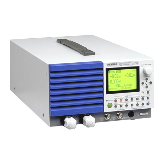
PLZ - 4W
Oct. 2015
Series
Quick Reference
22
26
Display
29
LOAD
2
1
7
SWITCHING
LOAD
SWITCHING
LOAD key
SW ON key
1
7
Turns the load on and off. The LED lights
Turns switching mode on and off.
when the load is on and turns off when the
FREQ/DUTY key
8
load is off.
Sets the switching frequency or the duty
MODE key
2
ratio.
Sets the operation mode.
Th/TL (SHIFT+FREQ/DUTY) key
+CV (SHIFT + MODE) key
Sets the switching time (Th: HIGH/TL:
Adds CV to CC or CR mode.
LOW).
SET/VSET key
LEVEL key
3
9
Sets the fundamental settings (current/
Sets the switching level. The key lights
conductance/voltage/power).
when the level can be set.
MENU (SHIFT + SET/VSET) key
% (SHIFT + LEVEL) key
Used to set features and environment
Sets the switching level as a percentage of
settings, calibrate the PLZ, and display
the set value (0 % to 100 %).
product information.
RANGE key
4
Sets the range (L/M/H).
VRANGE (SHIFT + RANGE) key
Switches the voltage value range (15 V/150
V).
5
SLEW RATE key
Sets the slew rate value.
SHORT (SHIFT + SLEW RATE) key
Activates or deactivates the short function.
OPP/OCP key
6
Sets the power at which OPP is activated or
the current at which OCP is activated.
UVP (SHIFT + OPP/OCP) key
Sets the voltage at which UVP is activated.
You can download the most recent manuals from the following website.
http://www.kikusui.co.jp/en
23
24
25
15
27
16
28
18
19
31
30
17
32
20
3
4
5
6
10
11
8
9
12
13
14
21
PRESET/SEQ
* Red keys are lighted.
PRESET/SEQ
RECALL key
10
Recalls the saved panel settings into the
setup memory.
STORE (SHIFT + RECALL) key
Saves the panel settings to the setup memory.
11
ENTER key
Sets various values and releases alarms.
ABC (SHIFT + ENTER) key
Saves the panel settings to the preset
memory. After you press this key, press the
A, B, or C key.
A key
12
Recalls the settings in preset memory A.
When this key is pressed after the ABC key,
it saves the settings.
EDIT (SHIFT + A) key
Displays the sequence editing screen.
B key
13
Recalls the settings in preset memory B.
When this key is pressed after the ABC key,
it saves the settings.
RUN/STOP (SHIFT + B) key
Displays the sequence screen. Starts and
stops sequence execution.
C key
14
Recalls the settings in preset memory C.
When this key is pressed after the ABC key,
it saves the settings.
PAUSE (SHIFT + C) key
Temporarily stops or restarts sequences.
Miscellaneous
Main Specifications
Rotary knob
Ratings
15
Changes the settings. Press the knob to
Model
switch between coarse and fine adjustment.
Operating voltage (DC)
Contrast (SHIFT + knob)
Current
Power
Adjusts the contrast of the display.
1.
Minimum voltage at which the current starts flowing to the PLZ-4W is approximately 0.3 V.
key
16
2.
The minimum operating voltage (including the voltage drop due to the wire inductance component) in switching mode
The up key.
increases by 0.15 V per 1 A/μs at slew rate settings greater than 5 A/μs.
3.
The minimum operating voltage (including the voltage drop due to the wire inductance component) in switching mode
INS (SHIFT+
) key
increases by 0.3 V per 1 A/μs at slew rate settings greater than 5 A/μs.
Adds a step (sequence function).
Constant Current Mode (CC)
key
17
Model
The down key.
Operating range
DEL (SHIFT+
) key
Deletes a step (sequence function).
Accuracy of setting
key
18
The left key.
Input voltage
PREV (SHIFT+ ) key
variation
3
Returns to the previous screen.
key
19
1.
Full scale of H range
2.
Vin: Input terminal voltage of Electronic Load
The right key.
3.
When the input voltage is varied from 1.5 V to 150 V at a current of rated power/150 V.
NEXT (SHIFT+ ) key
Constant Resistance Mode (CR)
Switches to the next screen.
Model
LOCAL key
20
Operating range
Switches from remote mode to local mode.
LOCK (SHIFT + LOCAL) key
Enables or disables the key lock.
Accuracy of setting
SHIFT key
21
1.
Conductance [S] = Input current [A]/input voltage [V] = 1/resistance [Ω]
Enables the functions displayed in blue
2.
Converted value at the input current. At the sensing point.
below the keys.
3.
set = Vin/Rset
4.
Full scale of H range
5.
Vin: Input terminal voltage of Electronic Load
Display
Constant Voltage Mode (CV)
Model
Range display
22
Operating range
Displays the current and voltage ranges.
(key icon)
23
Accuracy of setting
Appears when the key lock is enabled.
Input current variation
(remote icon)
24
1.
At the sensing point during remote sensing under the operating range of the input voltage.
2.
With respect to a change in the current of 10 % to 100 % of the rating at an input voltage of 1.5 V (during remote sensing).
Appears during external communication.
Constant Power Mode (CP)
25
(COARSE/FINE icon)
Indicates whether the rotary knob is set to
Model
coarse or fine adjustment.
Operating range
Measured value display
26
Indicates the measured values (current,
Accuracy of setting
voltage, and power).
Operation status display
1.
M range applies to the full scale of H range.
27
Displays the current operation mode.
General
Elapsed time display
28
Model
Displays the amount of time that has
Input voltage range
elapsed since the load was turned on.
Operation mode display
29
Input frequency range
Displays the set operation mode.
Power consumption
30
Setting display
Displays the set value.
(short icon)
31
Appears when the short function is being
Chapter 3
executed.
6.6
Sequence Function
Multi display
32
6.7
Remote Sensing Function
6.8
External Control
Displays various settings and statuses.
In the appendix, there are explanations of the operation modes and the operating area and a sequence program creation table.
For information about remote control, see the communication interface manual (contained in the accompanying CD-ROM).
PLZ164W
PLZ334W
PLZ1004W
PLZ164WA
1
1.5 V to 150 V
2
33 A
66 A
200 A
165 W
330 W
1000 W
Range
PLZ164W
PLZ334W
PLZ1004W
PLZ164WA
H
0 A to 33 A
0 A to 66 A
0 A to 200 A
0 A to 33 A
M
0 A to 3.3 A
0 A to 6.6 A
0 A to 20 A
0 A to 3.3 A
L
0 A to 330 mA
0 A to 660 mA
0 A to 2 A
0 A to 330 mA
H, M
± ( 0.2 % of set + 0.1 % of f.s
1
) + Vin
2
/500 kΩ
L
± ( 0.2 % of set + 0.1 % of f.s )
H
2 mA
4 mA
10 mA
M
2 mA
4 mA
10 mA
L
0.1 mA
0.2 mA
0.6 mA
0.1 mA
Range
PLZ164W
PLZ334W
PLZ1004W
PLZ164WA
1
H
22 S to 400 μS
44 S to 800 μS
133.332 S to 2.4 mS
22 S to 400 μS
M
2.2 S to 40 μS
4.4 S to 80 μS
13.3332 S to 240 μS
2.2 S to 40 μS
L
0.22 S to 4 μS
0.44 S to 8 μS
1.33332 S to 24 μS
0.22 S to 4 μS
2
H, M
±(0.5 % of set
3
+ 0.5 % of f.s
4
) + Vin
5
/500 kΩ
L
± (0.5 % of set
3
+ 0.5 % of f.s)
Range
PLZ164W
PLZ334W
PLZ1004W
PLZ164WA
H
1.5 V to 150 V
L
1.5 V to 15 V
1
---
±(0.1 % of set + 0.1 % of f.s)
2
---
12 mV
Range
PLZ164W
PLZ334W
PLZ1004W
PLZ164WA
H
16.5 W to 165 W
33 W to 330 W
100 W to 1000 W
16.5 W to 165 W
M
1.65 W to 16.5 W
3.3 W to 33 W
10 W to 100 W
1.65 W to 16.5 W
L
0.165 W to 1.65 W
0.33 W to 3.3 W
1 W to 10 W
0.165 W to 1.65 W
---
±(0.6 % of set + 1.4 % of f.s
)
1
PLZ164W
PLZ334W
PLZ1004W
PLZ164WA
100 Vac to 240 Vac
100 Vac to 120 Vac/200 Vac to 240 Vac
(90 Vac to 250 Vac) single phase, continuous
(90 Vac to 132 Vac/180 Vac to 250 Vac)
47 Hz to 63 Hz
80 VA max.
90 VA max.
160 VA max.
450 VA max.
The User's Manual (contained in the accompanying CD-ROM)
contains the following additional information.
For First Time Users
6.9
Monitor Signal Output
8.3
6.10
Parallel Operation
8.4
8.1
Maintenance
Chapter 9
8.2
Confirming Status of the Fuse
PLZ664WA
0 V to 150 V
3
33 A
132 A
165 W
660 W
PLZ664WA
0 A to 132 A
0 A to 13.2 A
0 A to 1.32 A
2 mA
8 mA
2 mA
8 mA
0.4 mA
PLZ664WA
88 S to 1.6 mS
8.8 S to 160 μS
0.88 S to 16 μS
PLZ664WA
0 V to 150 V
0 V to 15 V
PLZ664WA
66 W to 660 W
6.6 W to 66 W
0.66 W to 6.6 W
PLZ664WA
single phase
1500 VA max.
Calibration
Malfunctions and Causes
Specifications
Advertisement
Table of Contents

Related Manuals for Kikusui PLZ164W


Summary of Contents for Kikusui PLZ164W
-
Page 1: Quick Reference
You can download the most recent manuals from the following website. Series http://www.kikusui.co.jp/en Rotary knob Ratings Changes the settings. Press the knob to Model PLZ164W PLZ334W PLZ1004W PLZ164WA PLZ664WA Quick Reference switch between coarse and fine adjustment. Operating voltage (DC) 1.5 V to 150 V... - Page 2 Turing on the Load ABC Preset Memory Other Settings • Soft Start • Response Speed The preset memory can be used to save and recall current, resistance, Make sure that the load is off. voltage, and power values. In CC mode and CR mode, you can use this function to raise the This is the speed at which the input current and voltage values are Select an operation mode.
Need help?
Do you have a question about the PLZ164W and is the answer not in the manual?
Questions and answers