Do you have a question about the TOS93 series and is the answer not in the manual?
Questions and answers
Pradeep Joshi
May 29, 2025
Does the scaneer needs to be calibration?
1 comments:
Mr. Anderson
May 29, 2025
Yes, the Kikusui TOS93 series scanner requires calibration. You can set a calibration period from 1 to 24 months or set it to "Infinity" to stop monitoring. When the calibration period elapses, it can either trigger a protection mode or show a warning depending on the Protection setting.
Part No. IB032321 Nov 2018 Contents 6 User’s Manual Component Names 7 
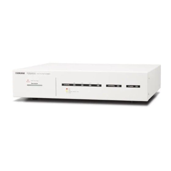
High voltage scanner TOS93 series Safety Precautions for Testing 9 TOS9320 Installation 13 External Control 25 Maintenance 29 Specifications 30 Appendix 34 DANGER This product generates high voltage! Improper operation can lead to serious accidents.
Page 2
Notes to the Supervisor • If the operators cannot understand the language used in this manual, translate the manuals into the appropriate language. • Make sure that the operators understand the information in this manual before they operate this product. •...
The TOS9320 High Voltage Scanner is an option for the • The TOS9320 High Voltage Scanner is also referred to as TOS93 Series Multifunction Safety Tester. It is equipped with a the TOS9320 scanner. function for distributing the test voltage supplied from the tes- •...
Notes on Usage Safety Precautions When using this product, be sure to observe the precautions in • When installing this product, be sure to observe the tem- the Safety Information manual. Items specific to this product perature and humidity ranges indicated below. are given below.
Checking Whether the Power Is On or Off ..14 ........14 Turning the power on ........14 Turning the power off Connecting to a TOS93 Series Tester..... 15 ........... 15 Before connecting ....17 Connecting to a TOS93 series tester Connecting TOS9320 Scanners to the EUT..
No. Name Function DANGER LED Lights in sync with the TOS93 series tester when the power is turned on, when a test p. 9 is in progress, when a high voltage is being output, or when there is residual voltage at the output terminals.
Page 8
Y terminals tial of your choice (high, low, or open) from the TOS93 series tester. IN HIGH VOLTAGE A terminal for connecting this product to a TOS93 series tester or to another p. 17 terminal TOS9320 scanner connected in parallel in order to receive the test voltage from the TOS93 series tester.
Risk of electric shock. The TOS9320 scanner supplies the 5.0 kVac, 7.2 kVdc, or higher voltage received from the TOS93 series tester to external devices. Handling the prod- uct improperly may lead to a fatal accident. To prevent accidents, strictly follow the precautions and always pay the utmost attention to safety concerns when you operate the product.
• During use, be sure to wear rubber gloves for electrical work. If obtaining these gloves is difficult, contact your Kikusui agent or distributor. During testing, the DANGER LED lights. Be careful because high voltage may be being output when the DANGER LED is lit.
EUT, the test leads, the test probes, and the areas near the output terminals. • After the output has been turned off, the TOS93 series tester’s internal discharge circuit goes into operation and discharges the output voltage. During testing and before this discharge completes, do not disconnect the tester from the EUT.
Immediately turn off the tester’s POWER switch, and disconnect the power cord from the outlet. Further, turn off the TOS9320 scanners’ POWER switches, disconnect the power cords, stop using the system immediately, and contact your Kikusui agent or distributor. Emergency measures There are two actions that you must carry out if, due to a malfunction in the test system or the EUT, there is a possibility of an emergency occurring such as electric shock or damage to the EUT.
If the supplied power cord cannot be used because the rated voltage or the plug shape is incompatible, have a qualified engineer replace it with an appropriate power cord that is 3 m or less in length. If obtaining a power cord is difficult, contact your Kikusui agent or dis- tributor.
Installation Checking Whether the Power Is On or Off Follow the procedure below when turning on or off each device in a system in which a TOS9320 scanner is connected. Turning the power on Turn on ( ) the POWER switch on the tester. POWER switch Turn on ( ) the POWER switch on the TOS9320 scanner.
Up to four TOS9320 scanners can be connected to a TOS93 series tester. The TOS9320 scanner is an option for the TOS93 series tester, but by using the CONTROLLER INTER- FACE connector, you can also control the scanner from an external device such as a Kikusui TOS5300 series withstanding voltage and insulation resistance tester 25).
Page 16
(for example, the tester assigns channels 1 to 4 to the TOS9320 scanner that it is directly connected to). The following table shows the mapping of the channel numbers as seen from the TOS93 series tester and the channel numbers of each scanner.
Installation | Connecting to a TOS93 Series Tester Connecting to a TOS93 series tester As an example, this section provides the connection diagram and procedure for connecting three TOS9320 scanners to a TOS93 series tester. Risk of electric shock. Connect the cables securely. If cable connections are incom- plete, the scanner chassis or the entire EUT may be charged to a high voltage.
Page 18
(p. 17). • If you remove or insert an interface cable while the POWER switch on the TOS93 series tester is on, the tester’s protection function is activated. The display will show the word “SCANNER.” To release the protection, press STOP.
EUT test points. As can be seen from the figure, the X terminal of each channel out- put (OUTPUT CH1-4) becomes a high voltage terminal, and the Y terminal becomes a low terminal. Each channel can be set to an electric potential of your choice (high, low, or open) from the TOS93 series tester.
Page 20
CH4 Y terminal OUT HIGH VOLTAGE terminal OUT LOW terminal IN HIGH VOLTAGE terminal IN LOW terminal OUT connector Control circuit IN connector SCANNER connector TOS9320 scanner HIGH VOLTAGE terminal LOW terminal TOS93 series tester 4 channel test system User’s Manual TOS9320...
Page 21
If you turn on the contact check function and press START on the TOS93 series tester, a contact check is performed before starting the test. The TOS93 series tester checks the continuity between the test leads and the EUT by turning on both relays x and y in the TOS9320 scanner for channels set to high or low, applying about 2 Vdc, and measuring the current.
Page 22
If measurements are unstable due to the effect of noise, such as when making highly sensitive measure- ments, using a shield box can stabilize the measurements.When using a shield box, connect the shield box’s chassis connection wire to the GUARD terminal on the rear panel. TOS93 series tester TOS9320 scanner HIGH...
Installation | Connecting TOS9320 Scanners to the EUT Connecting the EUT If you connect test leads to channels set to open, voltage may leak into those chan- nels through the stray capacitance in the scanner and between test leads during the test and may cause electric shock.
Installation | Connecting TOS9320 Scanners to the EUT Disconnecting test leads from the EUT To remove the test leads connected to the EUT, follow the procedure below. Check that the DANGER LED is turned off. Disconnect all the high-voltage test leads (red) from the EUT. Disconnect all the low-voltage test leads (black) from the EUT.
External Control The CONTROLLER INTERFACE connector can be used to control channels from an external device. Turning External Control On and Off External control is turned on and off using the EXTERNAL I/O switch on the rear panel. Setting the EXTERNAL I/O switch to on enables external control. EXTERNAL I/O switch User’s Manual TOS9320...
External Control CONTROLLER INTERFACE Connector Check the connector specifications, and then connect the external device to the CONTROLLER INTER- FACE connector. Pin arrangement CONTROLLER INTERFACE connector pin number Signal name IN/OUT Description 1CH HIGH SET Low level sets CH1 to high. 2CH HIGH SET Low level sets CH2 to high.
External Control | CONTROLLER INTERFACE Connector I/O signal circuit The input signal circuit and the output signal circuit share the same common. The input terminal is pulled up to +12 V by a resistor. Opening the input terminals is equivalent to high-level input. Input signal •...
External Control | CONTROLLER INTERFACE Connector Output signal usage example Driving a relay Use the output signal to drive a relay. To improve the safety of the circuit, we recommend that you insert a protection fuse or connect a diode. Relay 400 mA or less 30 V or less...
Maintenance Pre-Test Inspection To prevent accidents, inspect the following at the minimum before starting work. • Check that there are no breaks, cracks, or tears in the insulation of the high voltage test leads. • Check that the high voltage test leads are not broken. •...
3rd scanner: CH9 to CH12 4th scanner: CH13 to CH16 Contact check function Available Indicators DANGER Lights in sync with the TOS93 series tester CHANNEL Indicates the setting of each channel with color Red: High Green: Low Orange: Contact being checked...
Specifications Control switch EXTERNAL I/O switch for switching the following controls. ON: External control through the CONTROLLER INTERFACE OFF: Control from the TOS93 series tester CONTROLLER INTERFACE (external control) D-sub 25-pin connector. For the pin arrangement, see p. 26 Function Sets each channel to high or low or all channels to open.
Specifications General specifications Item Specifications Environment Installation location Indoors, 2000 m or less Spec guaranteed Temperature 5°C to 35°C (41°F to 95°F) range Humidity 20%rh to 70%rh (no condensation) Operating range Temperature 0°C to 40°C (32°F to 104°F) Humidity 20%rh to 80%rh (no condensation) Storage range Temperature -20°C to 70°C (-4°F to 158°F)
Appendix Timing Charts (Contact check operation) Setting conditions Model: TOS9301 (connect a high voltage scanner) Contact Check: ON CH1 to CH4 of the scanner: Low Rise Time: ON Test Time: ON Start the test with the SIGNAL I/O START H.V ON TEST 1CH High...
• KRB2-TOS: EIA inch rack Standard • KRB100-TOS: JIS millimeter rack standard For information about options, contact your Kikusui agent or distributor. To rack mount the product, remove the rubber feet from the product. When mounting the product on a rack, be sure to use support angles (auxiliary brackets) to safely support the product.
In some cases, the problem can be solved quite easily. If following the remedy does not solve your problem, contact your Kikusui agent or distributor. When contacting us about the product, please provide us with:...
Index accessories ........3 SCANNER connector....17 shield box ........22 specifications.......30 channel number ......16 component names......7 connections, number of....15 troubleshooting ......36 contact check ......21 CONTACT FAIL ......21 continuity check......21 X terminal ......19 CONTROLLER INTERFACE con- nector ......25 Y terminal ......19 DANGER LED.......9 EXTERNAL I/O switch ....25 GUARD terminal ......22...
Page 38
In either case, please contact your Kikusui agent or distributor. At that time, inform your agent or distributor of the “Part No.” written on the front cover of this manual.
Need help?
Do you have a question about the TOS93 series and is the answer not in the manual?
Questions and answers
Does the scaneer needs to be calibration?
Yes, the Kikusui TOS93 series scanner requires calibration. You can set a calibration period from 1 to 24 months or set it to "Infinity" to stop monitoring. When the calibration period elapses, it can either trigger a protection mode or show a warning depending on the Protection setting.
This answer is automatically generated