
Related Manuals for Kikusui 149-10A


Summary of Contents for Kikusui 149-10A
- Page 1 Part No. Z1-109-820, IA001705 Jul. 2016 OPERATION MANUAL High Voltage Digitalmeter 149-10A...
- Page 2 If you find any incorrectly arranged or missing pages in this manual, they will be replaced. If the manual gets lost or soiled, a new copy can be provided for a fee. In either case, please contact Kikusui distributor/agent, and provide the "Kikusui Part No." given on the cover.
-
Page 3: Power Requirements Of This Product
• Use a fuse element having a shape, rating, and characteristics suitable for this product. The use of a fuse with a different rating or one that short circuits the fuse holder may result in fire, electric shock, or irreparable damage. 149-10A... -
Page 4: Power Cord
Brown (LIVE) Green/Yellow (GND) Green or Green/Yellow (GND) Plug for USA Plug for China Plug for Europe NEMA5-15 CEE7/7 GB1002 Provided by Kikusui distributor/agent Kikusui agents can provide you with suitable power cord. For further information, contact Kikusui distributor/agent. 149-10A... -
Page 5: Safety Precautions
100 V and 200 V without switching between them. In such a case, use an appropriate power cord. For details, see the relevant page of this operation manual. 149-10A... - Page 6 • Use extra precautions such as using more people when relocating into or out of present locations including inclines or steps. Also handle carefully when relocating tall products as they can fall over easily. • Be sure the operation manual be included when the product is relocated. 149-10A...
- Page 7 , i t i s r e c o m m e n d e d t h a t p e r i o d i c maintenance, checking, cleaning, and calibration be performed. Service • Internal service is to be done by Kikusui service engineers. If the product must be adjusted or repaired, contact Kikusui distributor/agent. 149-10A...
-
Page 8: Safety Symbols
Describes technical terms used in this manual. Indicates action prohibited. Indicates general warning, caution, risk of danger. When this mark is indicated on the product, refer the relevant section of the Operation Manual. Indicates a protective conductor terminal. Indicates a chassis (frame) terminal. 149-10A... -
Page 9: Table Of Contents
3.2.2 To Correct the Meter Reading for High Impedance Measured Object 3.2.3 Measured Object's Polarity and Ground Chapter 4 Specifications ______________________ 16 Chapter 5 Calibration ________________________ 17 5.1 Calibration of Digitalmeter 5.2 Replacing the Fuse Chapter 6 Block Diagram _____________________ 19 149-10A... -
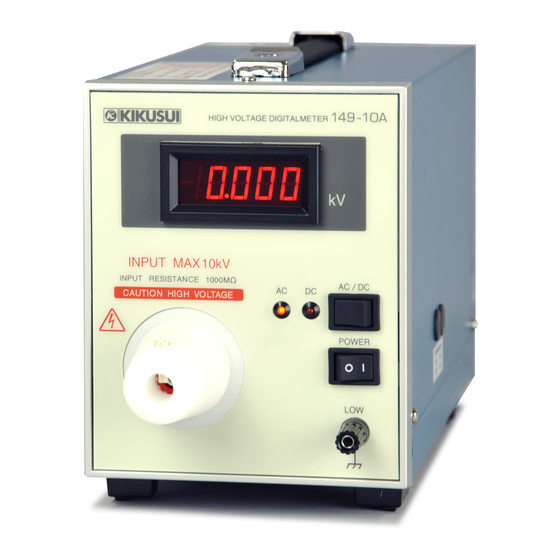
Page 10: Chapter 1 General Description
Chapter 1 General Description Kikusui Model 149-10A High Voltage Digitalmeter measures AC and DC voltages of up to 10 kV, with a high accuracy. As the meter input impedance is as high as 1000MΩ, the meter is best suited for measurement of voltages of high source impedance circuits. -
Page 11: Chapter 2 Preparation
Immediately upon receipt of the product, inspect it for any damage which might have been sustained while in transportation. If any signs of damage are found, contact Kikusui distributor/agent. 2.2 AC Line Requirements Before turning on the POWER switch of the tester, be sure that your AC line voltage. -
Page 12: Connecting The Power Cord
See section 2.2, "AC Line Requirements." 3. Connect the power cord to the AC inlet (AC LINE) on the rear- panel. 4. Connect the power cord plug to an outlet with a ground terminal. 149-10A... -
Page 13: Chapter 3 Operation Method
Terminal for high potential line of measured input voltage LINE VOLTAGE/FUSE Indicates the AC line voltage and fuse rating of the meter. FUSE Input power fuse Protective conductor terminal AC LINE Connect the supplied power cord here. Fig.3.1 Front panel/Rear panel 149-10A... -
Page 14: Measuring Method
• To measure with highest accuracy, warm up the 149-10A for at least 15 minutes. • If the 149-10A is used in dusty atmosphere or the meter is used continuously for a long time with a high voltage being input, dust may be collected on the INPUT terminal section. - Page 15 6. Connect the supplied high voltage test lead (red) to the high voltage side of the measured object. 7. Check that the 149-10A and measured object are connected as shown in Fig. 3.3. 8. Turn on the power of the measured object.
-
Page 16: To Correct The Meter Reading For High Impedance Measured Object
(protective conductor terminal) on the rear panel. As shown in Fig. 3.4, if the 149-10A is not grounded and the low and high voltage sides of the measured object are connected in reverse, the applied high voltage may damage the inside of the meter. - Page 17 If the 149-10A is grounded in Fig.3.4, terminals A and B of the measured object are shorted through the ground and the measured object is adversely affected. As such, if the low voltage side (GND side) of the measured object is unknown, determine it by following the procedure below, and connect properly.
-
Page 18: Chapter 4 Specifications
0˚C to 35˚C (32˚F to 95˚F), 80% RH and humidity: External dimensions : Overall Dimentions Maximum dimension Weight Approx. 3 kg (6.6 lbs) Power cord TL05-TOS High voltage test leads 1 set Accessories HTL2.5DH High voltage test lead Operation manual 149-10A... -
Page 19: Chapter 5 Calibration
• Before calibration, warm up the 149-10A for at least 60 minutes. ■ Calibration Set the 149-10A in the DC mode, apply a calibration voltage of 10 kV DC to the input terminal of the meter, and so adjust CALIBRATION (DC) semi-fixed resistor on the side panel of the 149-10A that it displays 10.000. -
Page 20: Replacing The Fuse
1. Turn off the POWER switch and unplug the power cord from the outlet. 2. Disconnect the power cord from the AC inlet on the rear panel. 3. Use a screwdriver to remove the fuse holder, as shown in Fig. 5.1. Fuse Fig. 5.1 Fuse holder 149-10A... -
Page 21: Chapter 6 Block Diagram
Chapter 5 Block Diagram 149-10A... - Page 22 KIKUSUI ELECTRONICS CORP. 1-1-3 Higashiyamata, Tsuzuki-ku, Yokohama, 224-0023, Japan Tel: +81-45-593-7570 Fax: +81-45-593-7571 http://www.kikusui.co.jp/en Website...
Need help?
Do you have a question about the 149-10A and is the answer not in the manual?
Questions and answers