Table of Contents
Advertisement
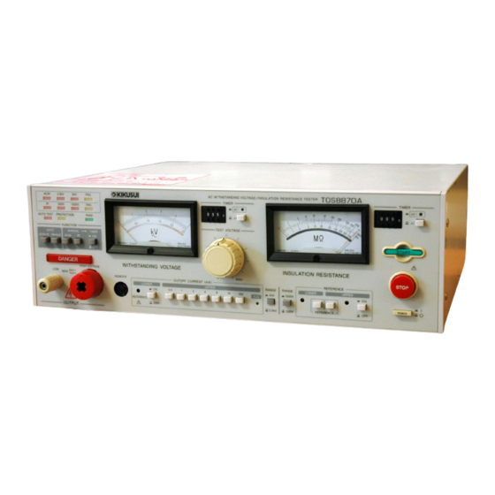
OPERATION MANUAL
WITHSTANDING VOLTAGE/
INSULATION RESISTANCE TESTER
TOS8870A
DANGER
This Tester generates high voltage!
○ Any incorrect handling may cause death.
○ Read Chapter 2 "WARNINGS AND CAUTIONS FOR
OPERATING THE TESTER" in this manual to prevent
accident.
○ Keep this manual near the tester for easy access of the
operator.
Part No. Z1-002-472, IB003175
Mar. 2004
Advertisement
Table of Contents

Related Manuals for Kikusui TOS8870A


Summary of Contents for Kikusui TOS8870A
- Page 1 Part No. Z1-002-472, IB003175 Mar. 2004 OPERATION MANUAL WITHSTANDING VOLTAGE/ INSULATION RESISTANCE TESTER TOS8870A DANGER This Tester generates high voltage! ○ Any incorrect handling may cause death. ○ Read Chapter 2 “WARNINGS AND CAUTIONS FOR OPERATING THE TESTER” in this manual to prevent ...
- Page 2 If you find any incorrectly arranged or missing pages in this manual, they will be replaced. If the manual it gets lost or soiled, a new copy can be provided for a fee. In either case, please contact Kikusui distributor/ agent, and provide the “Kikusui Part No.”...
- Page 3 • approach to any part connected to the output terminal while the power of the Tester is turned on. • the same action as above immediately after the power of Tester has been turned off. (in case of insulation resistance test) TOS8870A Safety Precautions...
-
Page 4: Power Requirements Of This Product
White (NEUTRAL) Black (LIVE) Brown (LIVE) Green/Yellow (GND) Green or Green/Yellow (GND) Plugs for USA Plugs for Europe Provided by Kikusui distributor/agent Kikusui distributor/agent can provide you with suitable AC power cord. For further information, contact Kikusui distributor/agent. TOS8870A Safety Precautions... -
Page 5: Safety Precautions
When replacing a fuse, use the one which has appropriate shape, ratings, and specifications. Cover • There are parts inside the product which may cause physical hazards. Do not remove the external cover. TOS8870A Safety Precautions... - Page 6 • To maintain performance and safe operation of the product, it is recommended that periodic maintenance, checking, cleaning, and calibration be performed. Service • Internal service is to be done by Kikusui service engineers. If the product must be adjusted or repaired, contact Kikusui distributor/agent. TOS8870A...
- Page 7 100V LOCK 110V AC LINE 120V 50 60Hz 220V 230V 240V WEIGHT APPROX 23kg KIKUSUI ELECTRONICS CORP. MADE IN JAPAN For Safety, be sure to connect this terminal to an electrical ground (safety ground). See "1.6 Grounding" TOS8870A Safety Precautions...
-
Page 8: Safety Symbols
Is placed before the sign “DANGER,” “WARNING,” or “CAU- TION” to emphasize these. When this symbol is marked on the product, see the relevant sections in this manual. Indicates a protective conductor terminal. Indicates a chassis(frame) terminal. Symbols TOS8870A Safety... -
Page 9: Overvoltage Category
Equipment of overvoltage IV is for use at the origin of the installation. Example of such equipment are electricity meters and primary overcurrent protec- tion equipment. Overvoltage category Overvoltage category Switchboard Drop wire Indoor wiring Equipment AC line Transformer Receptacle Overvoltage category Overvoltage category TOS8870A Overvoltage category... -
Page 10: Table Of Contents
2.5.2 Inhibition of shorting to earth ground ............. 10 Emergency handling ..................10 Troubleshooting ....................10 2.7.1 In case of trouble ................... 10 2.7.2 Fade out of DANGER lamp..............11 Attention for Trouble-Free Operation ............... 11 VIII Table of Contents TOS8870A... - Page 11 6) Reapplication of test voltage (retest) ................20 7) Checking discharge from DUT ..................20 Remote Control ....................21 1) Remote-control with the option..................21 2) Remote-control by the other control system ..............21 3) INTERLOCK terminal ....................23 Output Signals....................23 Special Test Modes..................26 TOS8870A Table of Contents...
- Page 12 Insulation resistance Tester ................38 Common Specifications ................... 39 Outline Drawing....................41 Options ......................42 1) Model RC01-TOS/RC02-TOS Remote Control Box ............. 42 2) Model HP01A-TOS/HP02A-TOS High Voltage Test Probe.......... 43 3) High Voltage Test Leadwires..................43 Table of Contents TOS8870A...
-
Page 13: Introduction
INTRODUCTION General Model TOS8870A is a combination of an withstanding voltage tester and an insulation resistance tester, and it is capable of performing withstanding voltage test and insulation resistance test in one continuous process. As for the withstanding voltage tester, the Tester can provide a maximum output voltage of 5 kV and an output capacity of 500 VA, and can be used for withstanding voltage test in compliance with JIS, UL, CSA, BS and other major electrical standards and ordinances. -
Page 14: Chapter 1 Setup
Unpacking The Tester should be checking upon receipt for damage that might have occurred during transporta- tion. Also check that all accessories have been provided. Should the Tester be damaged or accessory missing, notify your Kikusui agent/distributor. Accessories Item Parts No. -
Page 15: Precautions For Moving
For transportation, use the special packing material for the unit. ■ Transport the unit in its original package to prevent vibration and falls, which may damage the unit. If you require packing material, contact your Kikusui agent/distributor. ■ Do not move the unit by yourself. -
Page 16: Ac Line Requirements
100 V 110 V 120 V 220 V 230 V 240 V • Do not attempt to convert your Tester for AC line voltage change for yourself. Order WARNING your Kikusui agent/distributor for conversion of your Tester. SETUP 4 TOS8870A... -
Page 17: Connecting The Ac Power Cord
To make a secure grounding connection, use one of the following two methods: Plug the power cord into a three-pronged outlet with grounding installation. Connect the protective conductor terminal on the rear panel to a dedicated ground (GND) terminal securely using a tool. SETUP 5 TOS8870A... -
Page 18: Chapter 2 Warnings And Cautions For Operating The Tester
2.1.1 Wearing Insulation Gloves When handling the Tester, be sure to wear insulation gloves in order to protect yourself against high voltages. If no insulation gloves are available on your market, please order your Kikusui agent/dis- tributor for them. 2.1.2 Grounding the Tester Be sure to ground the Tester. -
Page 19: Warnings And Cautions When Operating The Tester
Change-over of the switches on the panel shall be made after confirming that the STOP switch has been pushed in and that the TEST VOLTAGE dial has been turned to the extreme left ("0" position). WARNINGS AND CAUTIONS FOR OPERATING THE TESTER 7 TOS8870A... -
Page 20: Suspension Of Testing
- the DANGER lamp has been turned off. In the case of insulation resistance test, DUT is charged after testing. Be sure to read "2.3.2 Cautions in electric charging in insulation resistance test". WARNINGS AND CAUTIONS FOR OPERATING THE TESTER 8 TOS8870A... -
Page 21: Cautions In Electric Charging In Insulation Resistance Test
HIGH VOLTAGE output terminal About 150 kΩ 0.01 MΩ µF Operates for about 70 ms LOW terminal TOS8870A Fig.2-5 Example of discharge of equivalent circuit WARNINGS AND CAUTIONS FOR OPERATING THE TESTER 9 TOS8870A... -
Page 22: Remote Controls Of The Tester
AC power cord from the socket of the power source, and suspend the operation of the Tester. WARNINGS AND CAUTIONS FOR OPERATING THE TESTER 10 TOS8870A... -
Page 23: Fade Out Of Danger Lamp
If the Tester shows any irregular performance, it is possible that a high voltage may be output irre- spective of the operator's will. Suspend the operation of the Tester immediately. • Never attempt to repair the Tester for yourself. Please order your Kikusui agent/dis- WARNING tributor for such service. -
Page 24: Chapter 3 Operation Procedure
With the CUTOFF CURRENT switch, set the high limit reference value (upper reference value) of leakage current of the DUT as required of standards, and other. If it is set to 108 mA or higher, PROTECTION results. OPERATION PROCEDURE 12 TOS8870A... -
Page 25: Setting The Test Time
Short the high voltage test leadwire to the LOW test leadwire to make sure that no high voltage is being delivered to the output terminal. Connect the LOW leadwire to the DUT. Connect the high voltage test leadwire to the DUT. OPERATION PROCEDURE 13 TOS8870A... -
Page 26: Test Procedure
The FAIL judgement can be made not only when the measured value is larger than the high limit reference value but also when it is smaller than the low limit reference value (0 to one-half of the high limit reference value). OPERATION PROCEDURE 14 TOS8870A... -
Page 27: Setting The Lower Reference Value
Set the LOWER ON/OFF switch in the OFF state. Turn the LOWER REFERENCE value control to the counterclockwise position. Connect the DUT as described in "6) Connecting the DUT". Make settings as shown in the flowchart on the Fig.3-2. OPERATION PROCEDURE 15 TOS8870A... - Page 28 (value 1). UPPER :High limit reference value of leakage current for withstanding voltage test. :Low limit reference value of leakage current for withstanding voltage test. LOWER Fig.3-2 Flowchart of set the LOWER REFERENCE value OPERATION PROCEDURE 16 TOS8870A...
-
Page 29: Single Insulation Resistance Test
The high and low limit reference values can be set with the potentiometers located at right and left of the switches. Set the values as required by the DUT. (To make a setting, press down the resistor with the trimming screw driver and then turn it.) OPERATION PROCEDURE 17 TOS8870A... -
Page 30: Setting The Test Time
Short the high voltage test leadwire to the LOW test leadwire to make sure that no high voltage is being delivered to the HIGH VOLTAGE terminal. Connect the LOW leadwire to the DUT. Connect the high voltage test leadwire to the DUT. OPERATION PROCEDURE 18 TOS8870A... -
Page 31: Test Procedure
The delay time is set at approximately 0.3 seconds. If the timer is set at a period shorter than 0.3 seconds, the effect of the above provision will be lost and a PASS judgement may be made erroneously. Be sure to set the timer for a period longer than 0.5 seconds. OPERATION PROCEDURE 19 TOS8870A... -
Page 32: Automatic Test
In case of "ACW → IR" test mode, DUT is charged after testing. Be sure to check WARNING discharge from DUT. Refer to "2.3.2 Cautions in electric charging in insulation resis- tance test" on page 9. OPERATION PROCEDURE 20 TOS8870A... -
Page 33: Remote Control
A 5-pin connector as per the DIN standard is required for the following operation. If it is difficult to obtain a DIN connector, contact your Kikusui agent/distributor. • Be extremely careful when using this method because the high voltage is on/off - WARNING controlled with an external signal. - Page 34 Low level input voltage : 0 V to 4 V Low level sweep out current : ≤ 5 mA Input pulse width : 20 ms minimum REMOTE control connector TOS8870A Photocupler ON STOP START 20 ms or more 20 ms or more Fig.3-6 The gates are pulled up to +15 V.
-
Page 35: Interlock Terminal
To cancel the protection mode by the interlock function, short-circuit the terminal to set it to the low level, then press the STOP switch on the front panel or input the STOP signal for remote control. INTERLOCK terminal TOS8870A (rear panel) Voltage, current rating of the S1 switch 30 VDC, 0.1 A or higher... - Page 36 Tester starts the test operation. Contact signals ■ The contact signals are only with contacts and without any power sources as Fig.3-10. Therefore, cannot drive any loads which have no power. TOS8870A SIGNAL OUT terminal TEST ON signal PASS signal IR/FAIL signal...
- Page 37 Use examples of contact signal ■ To drive a DC buzzer with an ACW/FAIL or IR/FAIL alarms. Closed when FAIL alarm is generated TOS8870A BUZZER Less than 30 V Less than 1 A Fig.3-11 To drive a lamp with the TEST ON signal.
-
Page 38: Special Test Modes
TOS8870A LOAD 100 VAC Less than 1 A R : Approx. 100 Ω, 2 W or over C : Approx. 0.1 µF, 250 VAC or higher (The R and C are reference values only. Select proper values in accordance with the actual conditions.) Fig.3-14... - Page 39 PROTECTION state are not reset. To reset the FAIL alarm and PROTECTIONS state, press the STOP switch on the front panel. This mode provides an effective means for confirming the FAIL alarm when HP01A-TOS or HP02A-TOS High Voltage Probe (optional) is used. Fig.3-20 FAIL ALARM mode OPERATION PROCEDURE 27 TOS8870A...
-
Page 40: Chapter 4 Operating Principle
WITHSTANDING VOLTAGE TESTER [10] [11] AC LINE VOLTAGE HIGH VOLTAGE RELAY REGULATOR TRANSFORMER OUTPUT [12] TERMINAL [14] [16] [13] CURRENT DETECTOR WINDOW COMPARATOR CONTROL CIRCUIT FAIL ALARM START STOP [15] PROTECTION CIRCUIT Fig.4-1 TOS8870A Block Diagram OPERATING PRINCIPLE 28 TOS8870A... -
Page 41: Description Of Individual Circuits
Boosts the voltage regulator output with a ratio of 1:25 or 1:50 into a high output voltage of 0 to 2.5 kV or 0 to 5 kV. The rating is 5 kV, 100 mA (500 VA) when the AC line voltage is 100 V. [12] Voltmeter Indicates the output voltage for withstanding voltage test. OPERATING PRINCIPLE 29 TOS8870A... -
Page 42: Zero-Start Switch
0 V level, thereby reducing transiential overshoots. START signal STOP signal TEST ON signal Test voltage waveform when mechanical relay is used Test voltage waveform when zero-start switch is used Fig.4-2 OPERATING PRINCIPLE 30 TOS8870A... -
Page 43: Chapter 5 Description Of Front And Rear Panel Items
PASS-FAIL judgment; when UPPER switch is pressed, the ohmmeter indicates the high limit refer- ence value. When both switches are pressed, the LOWER switch has a priority. The limit reference values are adjustable with the potentiometers located at right and left of the switches. DESCRIPTION OF FRONT AND REAR PANEL ITEMS 31 TOS8870A... - Page 44 When in the automatic test mode, the test period is as preset by the timer. When in the single test mode, use or unuse of the timer is selectable by the TIMER ON/OFF switch located in the right hand side. DESCRIPTION OF FRONT AND REAR PANEL ITEMS 32 TOS8870A...
- Page 45 PROTECTION state and have pressed the STOP switch, the most probable cause is a failure of the Tester. Immediately stop using the Tester. [16] OUTPUT HIGH VOLTAGE (HIGH VOLTAGE terminal) The hot line of the test voltage. DESCRIPTION OF FRONT AND REAR PANEL ITEMS 33 TOS8870A...
- Page 46 The adjustor in the centre of the meter is used to adjust mechanical "0". [21] TIMER Presets the insulation resistance test period. See " Selecting the timer range" on page 18. DESCRIPTION OF FRONT AND REAR PANEL ITEMS 34 TOS8870A...
-
Page 47: Description Of Rear Panel Items
LOCK 110V AC L INE 120V 50 60Hz 220V 230V 240V WEIGHT APPROX 23kg KIKUSUI ELECTRONICS CORP. MADE IN JAPAN [27] CURRENT MONITOR [23] AC LINE [28] INTERLOCK [24] TEST MODE [22] PROTECTIVE CONDUCTOR TERMINAL Fig.5-2 [22] PROTECTIVE CONDUCTOR TERMINAL To ground the Tester to an electrical ground (safety ground). -
Page 48: Chapter 6 Maintenance And Calibration
The high voltage relay of the internal discharge circuit is a wearable component. In this regard, it is recommended to order your Kikusui agent/distributor to overhaul the Tester at every approximately 200,000 repetitions of tests (although the service intervals may differ depend- ing on the conditions of use). -
Page 49: Chapter 7 Specifications
When making an FAIL judgement test with the output terminals shorted, a certain level of no-load output voltage is needed due to the internal resistance of the output circuit. The voltages shown here are this type of output voltages. SPECIFICATIONS 37 TOS8870A... -
Page 50: Insulation Resistance Tester
At 25 ˚C ± 10 ˚C The 1st effective measuring range is from 1/1000 to 1/2 of the maximum effective scale value. The 2nd effective measuring range is from the above to the maximum effective scale value. SPECIFICATIONS 38 TOS8870A... -
Page 51: Common Specifications
The rating of the signal contacts is 125 VAC, 1 A, or 30 VDC, 1 A. Loudness of the buzzer is adjustable with a knob in common for the PASS signal and FAIL alarm. SPECIFICATIONS 39 TOS8870A... - Page 52 Power consumption of the instrument modified to operate on an AC line voltage other than 100 V is as follows. 110 V / 120 V: 25 VA or less 220 V / 230 V / 240 V: 45 VA or less SPECIFICATIONS 40 TOS8870A...
-
Page 53: Outline Drawing
7.4 Outline Drawing Unit : mm Fig.7-1 SPECIFICATIONS 41 TOS8870A... -
Page 54: Options
RC01-TOS :200 W × 70 H × 39 D mm (7.9 W × 2.8 H × 1.5 D in.) RC02-TOS :330 W × 70 H × 39 D mm (13 W × 2.8 H × 1.5 D in.) RC01-TOS RC02-TOS Fig.7-2 SPECIFICATIONS 42 TOS8870A... -
Page 55: Model Hp01A-Tos/Hp02A-Tos High Voltage Test Probe
For details, refer to Item "FAIL ALARM" on Chapter 3 "3.7 Special Test Modes" on page 26. 3) High Voltage Test Leadwires Model Voltage rating Length TL01-TOS 5 kVAC rms, 50/60 Hz Approx. 1.5 m TL02-TOS 5 kVDC Approx. 3 m SPECIFICATIONS 43 TOS8870A...
Need help?
Do you have a question about the TOS8870A and is the answer not in the manual?
Questions and answers