
Related Manuals for Cyber Power MBP20HVIEC6


Summary of Contents for Cyber Power MBP20HVIEC6
- Page 1 User’s Manual MBP20HVAU3 MBP20HVDE3 MBP20HVIEC6 Cyber Power Systems, Inc. www.cyberpower.com K01-0000262-02...
-
Page 2: Important Safety Instructions
CAUTION! To avoid electric shock, turn off and unplug the unit before DRYERS TO MBP OUTPUT SOCKETS! installing the input/output power cord with a ground wire. Connect the ground wire prior to connecting the line wires! Copyright © 2012 Cyber Power Systems, Inc. - Page 3 IEC, AU or DE MBP (Maintenance Bypass PDU) C14/C19 Power cord (1) User’s manual Register card Flat head screws: M4X8L (4) Pan head screws: M5X12L (4) Rackmount brackets (2) Cable Ties (4) Power Cord Retention Clips (4) Copyright © 2012 Cyber Power Systems, Inc.
-
Page 4: Hardware Installation
MBP mounted horizontally in a rackmount MBP mounted vertically in a rackmount ○ ○ ○ ○ Wall-mounted ○ ○ MBP mounted with UPS in tower mode MBP mounted with UPS in rackmount mode Copyright © 2012 Cyber Power Systems, Inc. - Page 5 Connect the input/output as shown in the following diagram. C14/C19 Power cord C13/C20 Power cord 1K/1.5K configuration C14/C19 Power cord C13/C20 Power cord 2K configuration C19/C20 Power cord C20/C19 Power cord 3K configuration Copyright © 2012 Cyber Power Systems, Inc.
- Page 6 Place a Retention Clip on the power cord. Insert the power cord to the MBP. Align and Insert the Cable Tie into the Retention Clip. Step 3: Fasten Retention Clip Push the Retention Clip until it touches the plug and fasten the Retention Clip. Copyright © 2012 Cyber Power Systems, Inc.
-
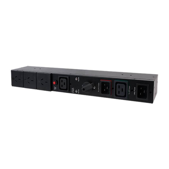
Page 7: Basic Operation
8. “Utility Power” Inlet 4. “Bypass” LED Indicator Connect the AC Power cord to a properly wired and grounded outlet. Indicate that the connected equipment is supplied directly by utility power. MBP20HVIEC6 MBP20HVAU3 MBP20HVDE3 Copyright © 2012 Cyber Power Systems, Inc. - Page 8 Switch is turned to “Bypass”. Cyber Power Systems, Inc. www.cyberpower.com © Entire contents copyright 2012 Cyber Power Systems, Inc., All rights reserved. Reproduction in whole or in part ® ® without permission is prohibited. PowerPanel Business Edition and PowerPanel Personal Edition are trademarks of Cyber Power Systems, Inc.
Need help?
Do you have a question about the MBP20HVIEC6 and is the answer not in the manual?
Questions and answers