Lexicon RV-5 User Manual
Lexicon rv-5: user guide
Hide thumbs
Also See for RV-5:
- User manual (202 pages) ,
- Supplementary manual (7 pages) ,
- Specifications (4 pages)
Table of Contents
Advertisement
Advertisement
Table of Contents
Troubleshooting

Related Manuals for Lexicon RV-5


Summary of Contents for Lexicon RV-5
- Page 1 RV-5 Receiver User Guide...
-
Page 2: Important Safety Instructions
Increase the separation between the equipment and the receiver. • Connect the equipment into an outlet on a circuit different from that to which the receiver is connected. • Consult the dealer or an experienced radio/ television technician for help. - Page 3 Lexicon, “Logic 7”, and the L7 logo are registered trademarks of Harman International Industries, Inc. Manufactured under license from Dolby Laboratories. “Dolby”, “Pro Logic”, and the double-D symbol are trademarks of Dolby Laboratories. “DTS” and “DTS-ES | Neo:6” are registered trademarks of DTS, Inc. and “96/24” is a trademark of DTS, Inc.
-
Page 4: Documentation Conventions
Introduction DOCUMENTATION CONVENTIONS This document contains general safety, installation and operation instructions for the RV-5 Receiver. It is important to read this user guide before attempting to use the product. Pay particular attention to safety instructions. Note: This manual is not intended as a general reference guide for home theater systems. If you’re uncertain how to proceed in setting up or maintaining your system, seek the advice of a professional installer or ask your dealer for their recommendations. -
Page 5: Table Of Contents
Utilizing Spare Channels ... 2-8 Tuner, PC, & Dock Overview... 2-9 Remote Control Overview ... 2-9 Operation Considerations ... 2-9 RV-5 Menu Overview ... 2-10 Menu Navigation ... 2-10 Remote Control Buttons ... 2-11 Menu Options ... 2-12 Menu Item Selection ... 2-12 Remote Control Light Button ... - Page 6 PC Controls ...5-4 Setting Up to Play ... 5-4 Playing PC Media ... 5-5 Dock Functionality...5-6 Connecting the Dock to the RV-5 ... 5-6 Selecting the Correct iPod Insert ... 5-6 Docking the iPod ... 5-7 Dock 2-line Display Characteristics ... 5-7 Controlling the iPod With the RV-5 ...
- Page 7 About the RV-5... 1-2 Product Registration ... 1-2 Highlights ... 1-2 What’s in the Box ... 1-3 Available Options ... 1-3 D-1 iPod Docking Station... 1-3 RF-1 Receiver... 1-3 Installation Considerations... 1-4 Remote Control Battery Installation ... 1-4 Getting Started...
-
Page 8: About The Rv-5
With the optional dock accessory, iPod owners can even connect and play their iPod through the RV-5. The RV-5 is designed to serve as the control center for your home theater system. A landmark product for Lexicon, the RV-5 offers capabilities never before offered as well as breaking ground with several brand new features. -
Page 9: What's In The Box
- you need only place the RF-1 Receiver in the rack or cabinet, or attach an emitter to the RV-5 front panel over the IR receiver. Every time a command is sent from the remote control, it sends both a standard IR and an RF signal. -
Page 10: Installation Considerations
Pay particular attention to the instructions below and to other precautions that appear throughout this user guide. install the RV-5 on a solid, flat, level surface such as a table or shelf. select a dry, well-ventilated location out of direct sunlight. -
Page 11: Basic Operation
Making Connections With the Amplifier Output... 2-8 Utilizing Spare Channels... 2-8 Tuner, PC, & Dock Overview... 2-9 Remote Control Overview ... 2-9 Operation Considerations... 2-9 RV-5 Menu Overview ... 2-10 Menu Navigation ... 2-10 Remote Control Buttons... 2-11 Menu Options... 2-12 Menu Item Selection ... 2-12 Remote Control Light Button ... -
Page 12: Front Panel Overview
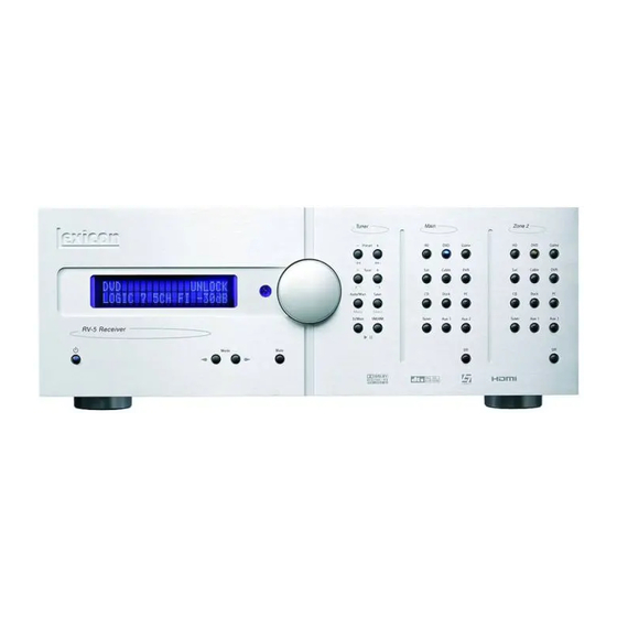
Basic Operation FRONT PANEL OVERVIEW The RV-5 is shown below. The numbers in the front panel illustration correspond with the numbered items in the text. 1. Front Panel Display 2. IR Receiver 3. Volume Knob 4. Tuner/iPod Control Buttons 5. Main Zone Input Selection Buttons 6. -
Page 13: Front Panel Display
Main Zone. When the RV-5 is in Standby, pressing a Main Zone input selection button powers on the RV-5, selects the input in the Main Zone, and turns off Zone 2. 6 ZONE 2 INPUT SELECTION BUTTONS Individually select each of the twelve inputs available in Zone 2. -
Page 14: Mode Buttons
Z o n e 2 i n p u t s e l e c t i o n b u t t o n a c t i v a t e s t h e corresponding input in Zone 2. When the RV-5 is in Standby, pressing a Zone 2 input selection button powers on the RV-5, selects the input in Zone 2, and turns off the Main Zone. 7 ZONE 2 OFF BUTTON Deactivates Zone 2. -
Page 15: Rear Panel Overview
Basic Operation REAR PANEL OVERVIEW The RV-5 rear panel is shown below. The numbers in the rear panel illustrations correspond with the numbered items in the text. 1. Microphone Input Connector 2. 8-CH Analog Audio Input Connector Array 3. Stereo Analog Audio Input Connectors 4. -
Page 16: Zone 2 Audio Output Connectors
3.5 mm mono mini phone jacks. The OUT 1 connector is the power trigger and is not configurable; it is activated when the RV-5 is powered on or taken out of Standby, and deactivated when the RV-5 is powered off, either from the rear panel or by putting the RV-5 into Standby mode. -
Page 17: S-Video/Composite Input Connectors
Standby button or remote control ON & OFF buttons can be used to activate and deactivate standby mode. When the RV-5 is powered off via the rear panel switch, the Standby and ON modes are not available. -
Page 18: Amplifier Overview
19 DOCK CONNECTOR Provides an interface for an iPod, which can then be accessed through the RV-5. To use this feature, the D-1 Dock option must be installed to the rear panel DOCK connector. With a compatible iPod connected to the RV-5, selecting the DOCK input allows you to play audio files from the iPod. -
Page 19: Tuner, Pc, & Dock Overview
TUNER, PC, & DOCK OVERVIEW The Tuner, PC, & Dock inputs are the only “hard-wired” inputs in the RV-5 Receiver. Unlike the other inputs, these three have very specific audio-only functionality. The Tuner input is for use with the internal AM/FM radio tuner. The PC input is tied to the USB input on the rear panel and is for use with media player software on a connected PC computer. -
Page 20: Rv-5 Menu Overview
RV-5 menu structure and has three branches: AUDIO CONTROLS, VIDEO STATUS, and SETUP. Note: The DVD menu layer of the touch screen controls the Lexicon RT-20 and RT-10, if installed. The AUDIO CONTROLS menu controls the audio-specific parameters, such as treble and bass, as well as providing an audio status menu. -
Page 21: Remote Control Buttons
14. EXIT 15. Transport functions (PLAY for source components Note: These are the names and functions for the universal remote control. For the RV-5 specific remote control functions, refer to the Command Matrix on the following page. Basic Operation , STOP... -
Page 22: Menu Options
Note: A brief description of each function is given in the table but refer to the Table of Contents for additional information on each function. For additional information on using and programming the remote control, refer to Appendix C. arrow Lexicon... - Page 23 (iPod controls) (PC controls) IPOD- Toggles the Auto EQ iPod parameter between ON & OFF. PRE1 IPOD+ Sets the RV-5 to the iPod Autocal Preset 1 saved values PRE2 CLIK PC II Sets the RV-5 to the iPod wheel click,...
- Page 24 Steps through the VIDEO STATUS menu INFO Steps through the AUDIO STATUS menu *The MAIN menu level does NOT control the RV-5. The remote control touch screen heading must read “LEX”, “TUNER”, or “ZONE 2” in order to control the RV-5 Receiver. TUNER...
- Page 25 Changes Front panel display illumination PAUSE (unused) PLAY *The MAIN menu level does NOT control the RV-5. The remote control touch screen heading must read “LEX”, “TUNER”, or “ZONE 2” in order to control the RV-5 Receiver. Basic Operation TUNER...
- Page 26 Aux 1 input Main Zone Enter Aux 2 input *The MAIN menu level does NOT control the RV-5. The remote control touch screen heading must read “LEX”, “TUNER”, or “ZONE 2” in order to control the RV-5 Receiver. TUNER ZONE 2...
- Page 27 Setup ... 3-2 Display Setup ... 3-3 Speaker/EQ Setup ... 3-5 Rear Amp ... 3-6 Manual ... 3-6 Semi Autocal ... 3-6 Full Autocal ... 3-7 Manual Speaker Setup... 3-9 Speakers Menu... 3-10 Speaker Distances Menu ... 3-11 Output Levels Menu... 3-12 Input Setup ...
-
Page 28: Setup Setup
Note: When a source is active, changing some audio or video parameters may cause the Main Zone audio to briefly mute the incoming source. If Zone 2 is set to DOWN MIX, the Zone 2 audio will also briefly mute. Lexicon... -
Page 29: Display Setup
DISPLAY SETUP SETUP Selects the CONNECTION parameter, which identifies the active video output connectors on the RV-5 rear panel. The following list of conditions identify the behavior of this parameter. • If ANALOG is selected, only the analog video connectors are available and will output the video signal. - Page 30 On the remote control, this parameter is controlled by the button while in the touch screen LEX or TUNER menus. Note: When the RV-5 is powered off or put into Standby mode, any changes to the BRIGHTNESS parameter are not saved. So when the RV-5 is powered on or taken out of Standby mode again, the BRIGHTNESS parameter will be set to FULL.
-
Page 31: Speaker/Eq Setup
RV-5 SPEAKER/EQ SETUP Select the SPEAKER/EQ SETUP menu to configure the Main Zone audio output connectors for the desired speaker setup. The Main Zone includes eight audio output connectors labeled Front L/R, Center, Subwoofer, Side L/R and Rear L/R. SETUP... -
Page 32: Rear Amp
REAR AMP, ZONE 2 In order to perform this test, the following initial setup is required: • All of the speakers are connected to the RV-5 and positioned in the listening space. • The cross-over points for each speaker are set through the MANUAL setup menu. -
Page 33: Full Autocal
In order to perform this test, the following initial setup is required: • All of the speakers are connected to the RV-5 and positioned in the listening space. • A monitor is connected to the RV-5 for viewing the OSD during the procedure. - Page 34 Setup Lexicon The microphone should be held within two feet of the speaker baffle as a test tone is sent to the speaker. The Subwoofer test is done in two parts. The user is instructed to hold the microphone to the left of the primary listening position and then to the right of the primary listening position.
-
Page 35: Manual Speaker Setup
RV-5 MANUAL SPEAKER SETUP Selecting the SETUP menu SPEAKER/EQ SETUP menu MANUAL option opens the MANUAL menu, which is used to manually set the speaker distances, cross-over points, and output levels. SETUP SPEAKER/EQ SETUP MANUAL SPEAKERS SPEAKER DISTANCES OUTPUT LEVELS... -
Page 36: Speakers Menu
When the speaker setup does not include side speakers, select NONE to redirect side channel signals to the Front L/R output connectors. If the Rear/Z2 L/R parameter is also set to NONE, the RV-5 will redirect surround channel signals to the Front L/R output connectors. FULL, 40 to 120HZ... -
Page 37: Speaker Distances Menu
NONE to redirect rear channel signals to the Side L/R output connectors. If the Side L/R parameter is also set to NONE, the RV-5 will redirect surround channel signals to the Front L/R output connectors. Note: When the Rear/Z2 L/R parameter is set to NONE, Dolby Digital PLIIx modes and DTS(-ES) decoding are not available. -
Page 38: Output Levels Menu
Subwoofer2 - can be set individually. Note: The speaker output level settings may affect the maximum volume level of the RV-5 Receiver. The maximum volume level is +10 dB minus the maximum output level setting of any speaker. Thus, if your Front L/R output levels are set to +3.0 dB, then the maxium allowable volume level... - Page 39 RV-5 To activate the Test Tone: 1. Press the Menu or Select button to enter the Menu structure. 2. Select Setup from the Main menu. 3. Select Speaker/EQ Setup. 4. Select Manual. 5. Select Output Levels. 6. Press the remote control arrows to highlight the Test Tone parameter.
-
Page 40: Input Setup
Allows the user to customize the name of the selected input. Custom input names can include up to eight characters. Note: A custom name cannot be assigned to the Tuner input. Lexicon ADVANCED VIDEO 1 ADVANCED VIDEO 2 FLESHTONE NR: ON... - Page 41 RV-5 To Customize the Name of the Selected Input: 11. Select the input and enter the Input Setup menu. 12. Select the Name parameter. Note that a blinking square appears in the first letter position. 13. Using the arrows, scroll through the letter list until you find the first desired letter.
- Page 42 Note: If VIDEO OUT is set to AUTO when the component input is not copy protected, the component output is always set to 1080i format. If the video monitor does not support 1080i format, the signal will not display correctly. Lexicon...
- Page 43 The parameter, when set to ON, identifies if there is both a digital and analog signal present to the input. If this condition is true, then the RV-5 prioritizes the digital signal over the analog signal. When the digital signal is interrupted, then it switches to the analog signal.
-
Page 44: Advanced Video
The STANDARD parameter activates the “standard” decoder of the source input. The USE LAST selection allows the RV-5 software to “remember” the last used listening mode for any given input source. Once selected, that mode will always be active on the corresponding input until another listening mode is selected. - Page 45 RV-5 Note: If you have 5.1-channel or 7.1-channel ANALOG AUDIO assigned to an Input using the BYPASS listening mode, only the Front Left and Front Right channels will be sent to Zone 2 OUT with the ANALOG setting. In this condition, DOWN MIX is not available.
- Page 46 CRT-based displays and digital sources. The Sharpness adjustment range is 0 to 100 in single increments. ADVANCED VIDEO 2 FLESHTONE NR: ON COMPNT ENHANCE: ON BRIGHTNESS: 100 CONTRAST: 100 COLOR: 100 INPUT SETUP SHARPNESS ADVANCED VIDEO Lexicon 0 TO 100...
- Page 47 RV-5 Most of the following Advanced Video parameters are simple ON/OFF toggle switches that apply to each input independently. FEATURE Noise Reduction X-Color Suppressor DCDi Interpolation Film Mode Detect Film Mode Edit Detect Component Video Enhancement Fleshtone NR NOISE REDUCTION...
- Page 48 Changes the color of the video to compensate for over- or under- color saturation conditions. The COLOR adjustment range is 50 to 150 in single increments. OFF, ON FLESHTONE NR OFF, ON COMPNT ENHANCE 50 TO 150 BRIGHTNESS 50 TO 150 CONTRAST INPUT SETUP ADVANCED VIDEO COLOR Lexicon 50 TO 150...
-
Page 49: Listening Modes
LISTENING MODES The RV-5 has a large selection of listening modes to choose from. The list of available listening modes is broken into two parts - the Mode Family and the Mode. The available listening modes vary depending upon the Mode Family selections, the input setup, and the incoming audio signal. -
Page 50: Available Listening Modes
Shaded cells indicate that there are no available modes in that Mode Family for that specific incoming data stream. Note: The table identifies all of the possible formats, but depending upon the Input setup and the Surround Configuration of the RV-5, all of these modes may not be available for selection. - Page 51 RV-5 Incoming DOLBY Dolby Datastream Dolby Digital 1.0 VS 2-SP REF & WIDE DOLBY DIGITAL DOLBY D STEREO Dolby Digital 2.0 PLIIx Film, Music, & Game PLII Film, Music, & Game Pro Logic VS 2-SP REF & WIDE VS 3-SP REF & WIDE...
- Page 52 Neo 6: 5ch Cinema Logic 7 5CH FILM Neo 6: 5ch Music Logic 7 5CH MUSIC Neo 6: 3ch Cinema Logic 7 7CH FILM Logic 7 7CH MUSIC Lexicon Stereo Stereo 2-ch Stereo Hall 1 5ch 2-ch Bypass* Hall 1 6ch...
-
Page 53: Listening Mode Descriptions
The following table provides a brief description of each listening mode. Logic 7 Film A proprietary Lexicon technology, Logic 7 is an advanced mode that extracts the maximum surround information from either surround-encoded pro- Logic 7 Music grams or conventional stereo material. Film 7.1 and Music 7.1 are tailored specifically for use with rear speakers, while Film 5.1 and Music 5.1 are spe- cifically formatted for use without rear speakers. - Page 54 The center channel is fed a summed mono mix of the in-phase material of the left and right channels. If the RV-5 has been configured for 6.1-/7.1-channel operation, both of these options are available for selection.
-
Page 55: 5.1-Channel & 7.1-Channel Direct Inputs
The upper right-hand corner of the front panel 2-line display may indicate status information regarding the incoming source. If a Dolby or DTS source is input and the RV-5 is configured to a surround system, the following status indicators may be displayed to indicate the state of the incoming source: •... -
Page 56: Surround Configuration
STEREO DOWN MIX: ON PCM 96kHz LOGIC 7: ON DOLBY PLII: ON DOLBY PLIIx: ON DTS NEO:6: ON 5/7 CH STEREO: ON Lexicon DOLBY MULTI-CHANNEL DOLBY 2.0 DOLBY VIRTUAL: OFF DOLBY PLII: ON LOGIC 7: ON DOLBY PLIIx: ON STEREO DOWN MIX: ON... - Page 57 LOGIC 7 DEFAULT Allows the user to choose Logic 7 as the default surround mode for all incoming audio signals. If this parameter is OFF, then the RV-5 selects the native format of the incoming signal as the default listening mode. If set to ON, then all incoming audio signals are defaulted to the Logic 7 listening modes.
-
Page 58: Dolby Configuration
Use the MID setting for mild compression and the MAX setting for more severe compression. R-1, R-2, R-3, O, F-1, F-2, F-3 DIMENSION DOLBY CONFIG PANORAMA DOLBY CONFIG OFF, MID, MAX DOLBY CONFIG NIGHT Lexicon OFF, ON... -
Page 59: Mute Levels
Dock input, refer to Section 5: Tuner, PC, & Dock Controls. Note: If the Main Zone is OFF when the RV-5 is put into Standby, when the iPod is plugged into the Dock, the RV-5 will power up but the Main Zone will remain OFF. - Page 60 Setup Lexicon 3-34...
-
Page 61: Audio Controls & Video Status
Audio Controls & Video Status Audio Controls ...4-2 Video Status ... 4-4... -
Page 62: Audio Controls
For more information on the AUTOCAL process, refer to Section 3: Setup. Lexicon EQ PRESET ACTIVE PS: USER PRESET 1: FACTORY PRESET 2: FACTORY... - Page 63 RV-5 To load a different saved EQ Preset into the system: 1. Decide which saved Preset location you want to load. 2. Select ACTIVE PS from the EQ PRESET menu. 3. Use the cursors to select the Preset location you want to load.
-
Page 64: Video Status
AUDIO: - - - MODE FAMILY: LOGIC 7 MODE: MUSIC 5.1 The AUDIO STATUS menu is an information-only menu identifying the current audio status of the RV-5. • INPUT identifies the currently selected input. • NAME identifies the customer-chosen name, if any, for the currently selected input. - Page 65 PC Controls...5-4 Setting Up to Play ... 5-4 Playing PC Media... 5-5 Dock Functionality ...5-6 Connecting the Dock to the RV-5 ... 5-6 Selecting the Correct iPod Insert ... 5-6 Docking the iPod ... 5-7 Dock 2-line Display Characteristics ... 5-7 Controlling the iPod With the RV-5 ...
-
Page 66: Tuner, Pc, & Dock Controls
ZONE 2 TUNER There is only one tuner in the RV-5 Receiver, but it can be accessed and output to either the Main Zone or the Zone 2 location. As a result, the Tuner display doesn’t indicate if the Main Zone or Zone 2 input is being altered, because only one tuner is being adjusted. -
Page 67: Tuner Controls
Main Zone heading on the front panel is lit with a blue LED; the Zone 2 TUNER input button lights with an amber LED. The front panel of the RV-5 and the 2-line OSD display TUNER and the current listening mode on the left side of the display; and the currently selected band frequency, preset location, and volume on the right side. -
Page 68: Pc Controls
The message, “Press again to write”, is displayed. Note: If no action is taken for five seconds, the RV-5 will time out and resume normal operation; the station will not be saved to the preset. -
Page 69: Playing Pc Media
Note: Whenever the USB jack is connected to the computer, the RV-5 will be selected as the sound card for the computer, even while the RV-5 is in... -
Page 70: Dock Functionality
Before connecting the Dock, turn the RV-5 off using either the main power switch or the Standby button. With the RV-5 off, press the button on each side of the connector at the end of the Dock cable and insert this plug into the DOCK connector on the rear panel of the RV-5. -
Page 71: Docking The Ipod
The ANLG signal type is identified on the top right side and the current volume setting of the RV-5 is identified on the bottom right side of the display, as shown:... -
Page 72: Controlling The Ipod With The Rv-5
RV-5. The Lexicon RV-5 remote control has a touch screen menu, page 3 of the “LEX” menu layer, devoted to controlling the iPod. In addition, the Tuner section of the RV-5 front panel is a multi-functional panel that also controls the iPod. The remote control menu buttons and the front panel tuner buttons provide identical controls. -
Page 73: Charging The Ipod
However, for the DOCK inputs, the OSD and front panel display reflect ONLY the Main Zone activity. Therefore, if the iPod is accessed in Zone 2, there is no visible indication on the RV-5 that a change has been made. - Page 74 Tuner, PC, & Dock Controls Lexicon 5-10...
-
Page 75: Troubleshooting & Maintenance
Troubleshooting & Maintenance Troubleshooting... 6-2 RV-5 Error Messages ... 6-7 Video Error Messages ... 6-7 Autocal Error Messages ... 6-8 Video Resolutions Table... 6-10 Routine Maintenance ... 6-12 Restoring Factory Default Settings ... 6-12... -
Page 76: Troubleshooting
1. Make sure the rear panel power switch is set to the ON position. 2. Attempt to power on the RV-5 with the front panel Standby button and remote control ON button. 3. Examine the power cord to ensure a good connection between the rear panel AC input connector and the wall outlet. - Page 77 Audio sounds distorted when using analog audio inputs. The likely cause for distorted audio while using the analog audio inputs is that the input voltage is too high. The RV-5 analog inputs have a maximum rating of 2 Vrms. Any input voltages higher than this limit will exhibit audible distortion.
-
Page 78: Installation Worksheet
2. Put the RV-5 into Standby mode. Wait 10 seconds. Then take the RV-5 out of Standby mode. 3. Set the rear panel power switch of the RV-5 to the OFF position. Wait 10 seconds. Then set the rear panel power switch to the ON position. - Page 79 VIDEO IN is set to NONE, but the monitor has a video error, or is showing a blue screen. When the VIDEO IN parameter is set to NONE, the RV-5 outputs a blue screen at 480i resolution. This blue screen cannot be disabled.
- Page 80 1. Make sure that the computer is properly connected to the USB input of the RV-5 Receiver. 2. Make sure that PC is selected as the active input on the RV-5 Receiver. 3. Make sure that the media player has been opened on the computer and is playing audio.
-
Page 81: Rv-5 Error Messages
RV-5 RV-5 ERROR MESSAGES RV-5 error messages are displayed on the OSD when certain error conditions exist. This section explains the meaning of these error messages and how to fix each problem. VIDEO ERROR MESSAGES The following error messages apply specifically to video issues. -
Page 82: Autocal Error Messages
BACK TO SPK/EQ SETUP the microphone is within two feet of the speaker under test, verify the sp eaker cables are connected properly, verify that the volume level is correct, and repeat the test. Lexicon SIDE-R: NO REAR-L: YES SIDE-L: YES... - Page 83 RV-5 SUBWOOFER CAL ERROR SUBWOOFER CAL ERROR Subwoofers detected: This error message will display w h e n t h e S u b w o of e r t e s t h a s SUBWOOFER 1: NO failed. Typically, this failure occurs...
-
Page 84: Video Resolutions Table
Troubleshooting & Maintenance VIDEO RESOLUTIONS TABLE The RV-5 Receiver is designed to allow flexibility in the selection of video output resolutions. However, there are restrictions on what resolutions can be made available due to incoming signal limitations. If you are not getting the expected resolution options for your video monitor, it is possible that there is an incompatability between the input setup selections and the incoming signal. - Page 85 RV-5 INPUT Video Mode Source Format 480i 480p HDMI 720p 1080i 480i 480p Component Analog 720p 1080i S-480i S-Video, Composite C-480i Analog S&C - 480i 480i 480p HDMI 720p 1080i 480i CONVERSION 480p Component Analog 720p 1080i S-480i S-Video, Composite...
-
Page 86: Routine Maintenance
Do not use a cloth made with steel wool or metal polish. If the RV-5 is exposed to a dusty environment, a low-pressure blower can be used to remove dust from its exterior surface. - Page 87 Appendix Specifications ... A-2 Declaration of Conformity... A-4...
-
Page 88: Appendix A Specifications
• 1 AM antenna • Input sensitivity = max input level 2Vrms Control • One RS-232, 9-pin, D-sub connector • One IR receiver, on front panel • One 3.5mm IR IN jack: Input Voltage: 3V - 15V Input Current: 10mA... - Page 89 RV-5 Component Video Performance Compatibility 3-channel (Y, Pr, Pb), format-independent Impedance 75Ω Insertion Loss <3dB Bandwidth >100MHz Amplifier Outputs Continuous Output 85W per channel, 8Ω, all channels driven, 20Hz to 20kHz Power Frequency Response 10Hz to 40kHz, +0, -2dB THD + Noise <0.05%, 20Hz to 20kHz, 1W...
-
Page 90: Declaration Of Conformity
• Depth*: 15.6 inches (397 mm) Weight • Net Weight: 39.7 lb (18 kg) • Gross Weight: 55.1 lb (25 kg) Rack-Mounting Lexicon built rack mount kit not available. Please seek alternative. Operating • Operating temperature: 0 to 45 C (32 to 113 F) Environment •... - Page 91 Main Menu: Setup ...B-3 Note: All parameter values shown in the following menu trees indicate the default parameter value if the RV-5 is restored to its factory default state. Setup Menu: Display Setup ... B-4 Setup Menu: Surround Config ... B-4 Setup Menu: Speaker/EQ Setup ...B-5...
-
Page 92: Main Menu: Audio Controls
BASS: 0dB TREBLE: 0dB AUDIO STATUS AUDIO STATUS INPUT: HD+ NAME: CONNECTOR: ANALOG 3 AUDIO: - - - MODE FAMILY: LOGIC 7 MODE: MUSIC 5.1 Lexicon EQ PRESET ACTIVE PS: USER PRESET 1: FACTORY PRESET 2: FACTORY PRESET 3: FACTORY... -
Page 93: Main Menu: Setup
RV-5 MAIN MENU: SETUP MAIN MENU SETUP AUDIO CONTROLS DISPLAY SETUP VIDEO STATUS SPEAKER/EQ SETUP SETUP INPUT SETUP SURROUND CONFIG DOLBY CONFIG MUTE LEVELS POWER ON SETTINGS DISPLAY SETUP CONNECTION: HDMI/DVI HDMI AUDIO OUT: NO ON-SCREEN DISPLAY FRONT PANEL DISPLAY... -
Page 94: Setup Menu: Display Setup
STEREO DOWN MIX: ON PCM 96kHz LOGIC 7: ON DOLBY PLII: ON DOLBY PLIIx: ON DTS NEO:6: ON 5/7 CH STEREO: ON Lexicon DOLBY MULTI-CHANNEL DOLBY 2.0 DOLBY VIRTUAL: OFF DOLBY PLII: ON LOGIC 7: ON DOLBY PLIIx: ON STEREO DOWN MIX: ON... -
Page 95: Setup Menu: Speaker/Eq Setup
RV-5 SETUP MENU: SPEAKER/EQ SETUP SETUP MAIN MENU DISPLAY SETUP AUDIO CONTROLS VIDEO STATUS SPEAKER/EQ SETUP SETUP INPUT SETUP SURROUND CONFIG DOLBY CONFIG MUTE LEVELS POWER ON SETTINGS SPEAKER/EQ SETUP REAR AMP: REAR SPK MANUAL PERFORMS SEMI-AUTOMATIC SEMI AUTOCAL CALIBRATION... -
Page 96: Setup Menu: Input Setup
X-COLOR SUPPRESS: ON COLOR: 100 DCDi INTERPOL: ON FILM DETECTION: ON FILM EDIT DETECT: ON DOCK TUNER AUX 1 None None None S-Video 2 None None Optical 2 Unplugged None TUNER None Lexicon AUX 2 S-Video 3 Optical 3 None... - Page 97 Setting Up the Remote Control... C-3 Lock Feature ... C-6 Advanced Customizing Tools ... C-6 Erasing Commands ... C-13 Restoring Factory Default Settings... C-14 Optional RF-1 Receiver ... C-14 Using the 3-Digit Code Library... C-15 3-Digit Pre-programmed Codes ... C-15 Appendix...
-
Page 98: Remote Control Programming
“learn” from another remote, one button at a time. The RV-5 remote control has many additional operating features to add convenience and enjoyment to the operation of any home entertainment system. -
Page 99: Setting Up The Remote Control
RV-5 SETTING UP THE REMOTE CONTROL The RV-5 remote control can be set up so that it controls all of the components of your home entertainment system, making remote access simple and efficient. There are two ways to set up the remote control: •... - Page 100 Button Learning procedure. The RV-5 remote control can “learn” commands from other remote controls, both old and new, one button at a time. Follow the steps below to allow your RV-5 remote control to learn the button commands from other remote controls in your home theater system.
- Page 101 1. Line up the RV-5 remote control with the other remote control, head-to-head, one or two inches apart. 2. On the RV-5 remote control, press and hold the MAIN and ENT (Enter) buttons at the same time. After about 3 seconds, “SETUP”...
-
Page 102: Lock Feature
To return to an original pre-programmed function, the learned function must be erased. LOCK FEATURE The RV-5 remote control has a locking feature, which prevents unauthorized use of the remote control. When the locking feature is active, all operations of the remote control are blocked. This feature can be used as a “child-lock”... - Page 103 RV-5 Back light Time Out: The back light feature lights the touch screen area and illuminates the buttons whenever the LIGHT button is pressed. The amount of time the back light remains on before timing out can be adjusted to your preferences.
- Page 104 Steps 4 to 8. 9. When finished, exit the Setup mode by pressing the MAIN button until the touch screen displays MAIN in the menu heading area. The remote control is in normal operation mode again. Lexicon...
- Page 105 RV-5 Favorite Channel Access: To access the Favorite Channel listings, press the MAIN button to display page 1 of the Main menu. Touch the FAV (Favorite Channel) button on the touch screen. A list of favorite TV & cable stations is now displayed.
- Page 106 Another option for the component button macros is to only send the macro if the component button is held down. The advantage of this option is that a normal press of the component button will simply Lexicon ) button. Each press adds button twice. The...
- Page 107 Cloning other Lexicon RV-5 Remote Controls: If you happen to own more than one RV-5 remote control, you can copy and transfer the setup from one remote to the other. Follow the instructions below to clone your RV-5 remote control.
- Page 108 5. The bottom of the display will then flash “PUNCH FROM”. Now select the MAIN component that has the volume commands that you want to use (for example, “LEX” for the RV-5 Receiver). The bottom of the touch screen flashes “SAVED”.
-
Page 109: Erasing Commands
RV-5 Note: The TEXT option allows the text of each menu to be changed. Refer to the “Customizing the Touch Screen” procedure, found earlier in this chapter, for instructions. 3. Touch the PAGE option. The menu name changes to “PAGE” and the component options are displayed. -
Page 110: Restoring Factory Default Settings
- you need only place the RF-1 Receiver in the rack or cabinet, or attach an emitter to the RV-5 front panel over the IR receiver. Every time a command is sent from the remote control, it sends both a standard IR and an RF signal. -
Page 111: Using The 3-Digit Code Library
AUX - Multimedia PCs, Xbox, iPod Controls, and Custom Installation Products Within each category, the code numbers are listed in rows by brand, such as Lexicon and Samsung. Some brands have more than one 3-digit code for you to try. 3-DIGIT PRE-PROGRAMMED CODES... - Page 112 280 374 550 KINERGETICS 140 220 KOSS 216 573 KRELL 072 150 376 384 KYOCERA LEXICON 120 235 236 237 357 358 359 360 361 362 363 364 LINN 124 377 LUXMAN 004 009 052 115 137 139 165 056 076 MAGNAVOX...
- Page 113 RV-5 AUDIO Manufacturer Codes SOUNDMATTERS SOUNDSTREAM 084 088 SUMO SUNFIRE 344 345 346 494 TAEKWANG TEAC 005 019 049 111 212 217 TECHNICS 122 176 177 178 193 200 219 257 262 THETA DIGITAL TOSHIBA 060 087 198 278 WARDS...
- Page 114 043 074 TIME WARNER 043 074 TOCOM 039 040 056 TOSHIBA UNITED CABLE 004 053 UNIVERSAL 005 007 014 032 035 VIDEOTRON VIEWSTAR 012 015 018 086 087 088 089 WIDE OPEN WEST 043 099 ZENITH 052 060 093 100 Lexicon...
- Page 115 RV-5 Manufacturer Codes ADCOM 042 062 AIWA 059 065 088 089 105 122 170 187 AKAI 085 195 202 231 232 AMEND ARCAM AUDIO ACCESS 119 147 AUDIO EASE AUDIO TECHNICA 037 057 CALIFORNIA AUDIO 008 103 CAPETRONIC CARRERA 057 080...
- Page 116 HARMAN KARDON 084 140 HITACHI INTEGRA 142 180 KENWOOD KISS 179 279 KRELL LEXICON 148 305 Note: 305 is factory default setting for Lexicon RT-20 057 074 091 LITEON 264 265 MAGNAVOX 066 096 MALATA MARANTZ 083 095 MERIDIAN MITSUBISHI...
- Page 117 RV-5 Manufacturer Codes NAKAMICHI ONKYO 035 076 180 OPPO PANASONIC 021 042 138 139 144 150 PHILIPS 066 083 095 105 166 PIONEER 023 092 099 107 108 131 POLAROID 233 234 237 PRIMARE 193 194 PROCEED PROSCAN 026 027...
- Page 118 MARANTZ MITSUBISHI OPTIMUS 013 049 PANASONIC PHILIPS PIONEER 106 117 121 RADIO SHACK REALISTIC RUNCO SANYO SHARP 013 152 SONY 053 110 TECHNICS THETA DIGITAL TOSHIBA 106 152 YAMAHA 043 129 PHONO Manufacturer Codes KENWOOD PIONEER YAMAHA 001 002 Lexicon...
- Page 119 RV-5 Manufacturer Codes CABLEVISION/VOOM DIRECTV ECHOSTAR/DISH 122 167 168 EXPRESSVU GENERAL ELECTRIC 106 150 151 GENERAL INSTRUMENT 148 HITACHI 139 140 HUGHES 068 108 117 154 161 162 165 166 MAGNAVOX MEMOREX MITSUBISHI 068 154 MOTOROLA NEXT LEVEL PANASONIC 142 160...
- Page 120 004 008 009 024 030 065 101 143 156 160 197 JENSEN 034 038 070 083 145 199 210 240 241 KENWOOD 070 197 KLOSS 002 059 043 143 154 197 004 102 106 112 113 116 119 127 143 243 284 363 365 LODGENET Lexicon...
- Page 121 RV-5 Manufacturer Codes LOEWE LOGIK LUXMAN 007 015 052 081 160 164 166 MAGNAVOX 003 004 022 059 060 061 063 064 094 127 160 164 197 226 239 273 MARANTZ 164 184 197 MATSUI MAXENT MEMOREX 004 007 072...
- Page 122 003 010 014 031 034 053 072 101 102 134 139 045 046 059 MINOLTA 013 020 MITSUBISHI 013 020 045 046 049 051 059 061 142 151 168 034 040 MULTITECH 024 034 012 023 039 043 048 NORDMENDE OPTONICA 053 054 Lexicon...
- Page 123 RV-5 Manufacturer Codes ORION PANASONIC 066 070 074 083 133 140 145 157 163 167 PENTAX 013 020 031 063 PHILCO 031 034 067 PHILIPS 031 034 054 067 071 101 156 PILOT PIONEER 013 021 048 PORTLAND PULSAR QUARTZ...
- Page 124 168 169 170 171 172 188 189 AUX-Media PC Controls DELL 261 262 GATEWAY 261 262 HAUPPAUGE 294 295 261 262 KEYSPAN SONY 261 262 TOSHIBA 261 262 WINBOOK 261 262 AUX-XBox Controls MICROSOFT/XBOX 107 408 AUX-iPod Controls APPLE/iPod BOSE KENSINGTON Lexicon...
- Page 125 Appendix Installation Worksheet ... D-2 3-Digit Preprogrammed Codes Worksheet ... D-6...
-
Page 126: Installation Worksheet
A/D SAMPLE RATE A/V SYNC DELAY TRIGGER 2 ZONE2 OUT** ADVANCED VIDEO INPUT TYPE SHARPNESS NOISE REDUCTION X-COLOR SUPPRESS DCDi INTERPOL FILM DETECTION FILM EDIT DETECTION FLESHTONE NR GAME CABLE DOCK TUNER AUX1 NONE NONE DOCK NONE TUNER Lexicon AUX2... - Page 127 RV-5 INPUT SETUP ADVANCED VIDEO (CONTINUED) COMPNT ENHANCE BRIGHTNESS CONTRAST COLOR SPEAKER SETUP AUTO SETTING REAR AMP**: _______ CROSS-OVER POINTS** DISTANCES (UNITS: ___)** OUTPUT LEVELS “ALL” INPUT** HD INPUT DVD INPUT GAME INPUT SAT INPUT CABLE INPUT DVR INPUT CD INPUT...
- Page 128 BASS TREBLE VIDEO CONTROLS 4:3 IN >16:9 DISPLAY** DOLBY CONFIG CENTER WIDTH DIMENSION PANORAMA NIGHT DISPLAY SETUP CONNECTION HDMI AUDIO OUT OSD: 2-LINE OSD OSD: MENU TIME OUT F/P DISPLAY: BRIGHTNESS F/P DISPLAY: TIME OUT Lexicon SETTING PLII** PLIIx** SETTING...
- Page 129 RV-5 R/P CONNECTIONS ANALOG AUDIO HD INPUT DVD INPUT GAME INPUT SAT INPUT CABLE INPUT DVR INPUT CD INPUT DOCK INPUT DOCK PC INPUT NONE TUNER INPUT TUNER AUX 1 INPUT AUX 2 INPUT TUNER FREQ / TUNER FREQ /...
-
Page 130: 3-Digit Pre-Programmed Codes Worksheet
Appendix D 3-DIGIT PRE-PROGRAMMED CODES WORKSHEET COMPONENT AUDIO CABLE LIGHT TAPE PHONO VCR2 XM RADIO IPOD X-BOX MANUFACTURER Lexicon CODE(S) USED... -
Page 131: Index
DIMENSION parameter, 3-32 DISPLAY SETUP menu, 3-2–3-3, 3-30, 3-32–3-33 dock input 2-line display characteristics, 5-7 charging the iPod, 5-9 connecting to the RV-5, 5-6 controlling the iPod, 5-8 DOCK AUTO POWER parameter, 3-33 Dock Functionality, 5-6 docking the iPod, 5-7... - Page 132 DOLBY CONFIG menu, 3-2 INPUT SETUP menu, 3-2, B-6 menu arrows, 2-10, 2-12 menu item selection, 2-10, 2-12 menu options, 2-12 MUTE LEVELS menu, 3-2 Lexicon navigation, 2-10 overview, 2-10 POWER ON SETTINGS menu, 3-2 SELECT button, 2-10 SETUP menu, 3-2, B-3...
- Page 133 Declaration of Conformity, A-4 installation considerations, 1-4 Product Registration, 1-2 routine maintenance, 6-12 specifications, A-2 What’s in the Box, 1-3 RV-5 error messages, 6-7 autocal errors, 6-8 video errors, 6-7 safety instructions, 1-ii SELECT button, 2-10 SEMI AUTOCAL menu, 3-6...
- Page 134 MUTE LEVELS menu, 3-33 V-PROCESS parameter, 3-15 X-COLOR SUPPRESS parameter, 3-21 Zone 2 input selection buttons, 2-3 INPUT SETUP menu, 3-2 mute levels paramater, 3-33 OFF button, 2-4 radio tuner, 5-2, 5-9 rear panel connectors, 2-6 ZONE-2 OUT parameter, 3-18 Lexicon...
-
Page 135: Limited Warranty
Harman Specialty Group Tel 781-280-0300 Fax 781-280-0490 3 Oak Park Drive Bedford, MA 01730-1413 www.lexicon.com What Limitations Implied Warranties? Any implied warranties, including warranties of mer- chantability and fitness for a particular purpose, are limited in duration to the length of this warranty.
Need help?
Do you have a question about the RV-5 and is the answer not in the manual?
Questions and answers