Advertisement
Quick Links
1
Insert the CY3210-PSoCEVAL1 kit DVD into
the DVD drive of your PC.
Install the kit contents, PSoC Designer,
and PSoC Programmer.
3
Plug in the MiniProg to the ISSP header
on the CY3210-PSoCEVAL1 board.
Connect the MiniProg to the PC using
the USB cable provided with the kit.
CY3210-PS
CEVAL1 EVALUATION KIT
O
QUICK START GUIDE
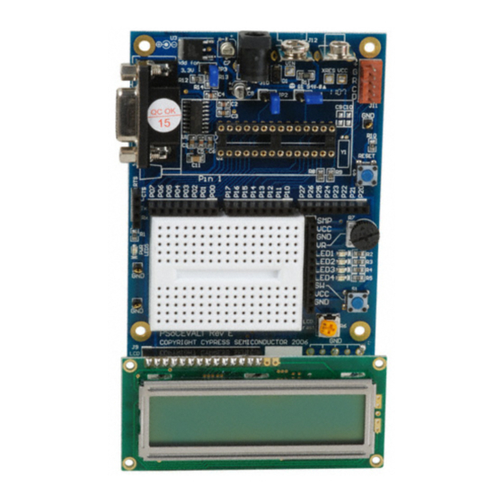
2
Remove the CY3210-PSoCEVAL1 board
from its package.
Place the character LCD provided with the
kit on J9.
Connect jumper (shunt) at JP1 and JP2.
Connect the single strand jumper wire
between P01 and VR.
4
Open PSoC Programmer; click on the
Toggle Power button to power the board.
Vary the potentiometer; the voltage is
measured by an ADC and is displayed in hex
format on the LCD module.
Advertisement

Related Manuals for Cypress CY3210-PSoCEVAL1


Summary of Contents for Cypress CY3210-PSoCEVAL1
- Page 1 CY3210-PS CEVAL1 EVALUATION KIT QUICK START GUIDE Insert the CY3210-PSoCEVAL1 kit DVD into Remove the CY3210-PSoCEVAL1 board the DVD drive of your PC. from its package. Install the kit contents, PSoC Designer, Place the character LCD provided with the and PSoC Programmer.
- Page 2 JP2 connects P27 to UART Tx Pin For the latest information about this kit, visit http://www.cypress.com/go/CY3210-PSoCEVAL1 © 2011-2012 Cypress Semiconductor Corporation. All rights reserved. All trademarks or registered trademarks referenced herein are the properties of their respective owners. Doc.#: 001-66719 Rev. *C...
Need help?
Do you have a question about the CY3210-PSoCEVAL1 and is the answer not in the manual?
Questions and answers