Table of Contents
Advertisement
Quick Links
Advertisement
Table of Contents

Related Manuals for Cypress CY3273


Summary of Contents for Cypress CY3273
- Page 1 CY3273 Cypress Low Voltage Powerline Communication Evaluation Kit Guide Doc. # 001-55382 Rev. *C Cypress Semiconductor 198 Champion Court San Jose, CA 95134-1709 Phone (USA): 800.858.1810 Phone (Intnl): 408.943.2600 http://www.cypress.com [+] Feedback...
- Page 2 Cypress Source Code and derivative works for the sole purpose of creating custom soft- ware and or firmware in support of licensee product to be used only in conjunction with a Cypress integrated circuit as speci- fied in the applicable agreement.
-
Page 3: Table Of Contents
A.1.1 Board Overview....................27 A.1.2 User Interface....................28 A.1.3 Transmit Amplification and Receive Filter............29 A.1.4 Power Supply ....................30 Layout ........................31 A.2.1 Top Layer .......................31 A.2.2 Ground Layer ....................32 CY3273 Cypress Low Voltage Powerline Communication Evaluation Kit Guide, Doc. # 001-55382 Rev. *C [+] Feedback... - Page 4 A.2.3 Power Layer....................33 A.2.4 Bottom Layer ....................34 A.2.5 Top Silkscreen ....................35 A.2.6 Bottom Silkscreen ..................36 Bill of Materials ......................37 CY3273 Cypress Low Voltage Powerline Communication Evaluation Kit Guide, Doc. # 001-55382 Rev. *C [+] Feedback...
-
Page 5: Introduction
CY8CPLC10 to transmit data at 2400 bps over low voltage (12 V to 24 V AC/DC) powerlines. This guide includes the following chapters: Chapter 1 provides a brief overview of the Cypress PLC solution. It describes the contents of the ■... - Page 6 C interface. To evaluate this kit, an external host must be created. The first option is to use a PC to install and run the Cypress PLC Control Panel GUI, which is ■ included with this kit. The PC interfaces to the CY3273 board through the CY3240-I2USB Bridge that is included with this kit.
-
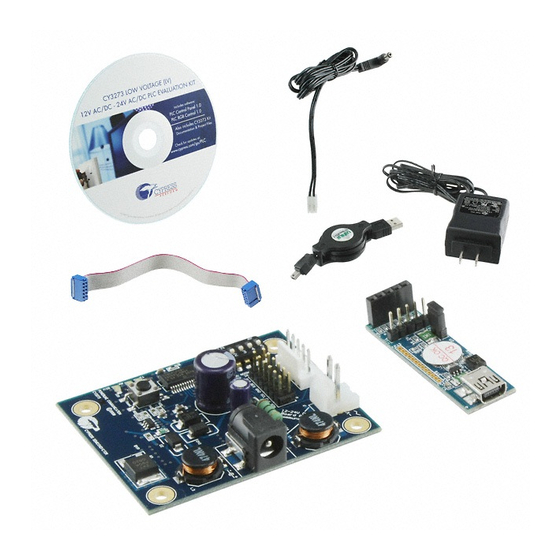
Page 7: Kit Contents
For more information regarding PSoC Programmer, supported hardware, and COM layer, go to ■ the PSoC Programmer web page: www.cypress.com/go/psocprogrammer ■ Designing an External Host Application for Cypress's Powerline Communication IC CY8CPLC10 - AN52478 http://www.cypress.com/?rID=37956 CY3273 Cypress Low Voltage Powerline Communication Evaluation Kit Guide, Doc. # 001-55382 Rev. *C [+] Feedback... -
Page 8: Additional Requirements
Introduction Additional Requirements The following Cypress demonstration kit is used in the example applications in this user guide. This kit is available for purchase from http://www.cypress.com/go/CY3210-PSoCEVAL1. CY3210-PSoCEval1 Kit This PSoC Evaluation Kit features an evaluation board and MiniProg1 programming unit. The evaluation board includes an LCD module, potentiometer, LEDs, and plenty of bread boarding space to meet all your evaluation needs. -
Page 9: Document Revision History
Click the File icon and then click Open. Displays an equation: Times New Roman 2 + 2 = 4 Text in gray boxes Describes cautions or unique functionality of the product. CY3273 Cypress Low Voltage Powerline Communication Evaluation Kit Guide, Doc. # 001-55382 Rev. *C [+] Feedback... - Page 10 Introduction CY3273 Cypress Low Voltage Powerline Communication Evaluation Kit Guide, Doc. # 001-55382 Rev. *C [+] Feedback...
-
Page 11: Getting Started
Getting Started This chapter describes how to install and configure the CY3273 - LV PLC Evaluation Kit. Kit Installation To install the kit software, follow these steps: 1. Insert the kit CD in your PC’s CD drive. The CD is designed to auto-run and the Kit Installer Startup Screen appears. - Page 12 Note If auto-run does not execute, double-click the cyautorun.exe file on the root directory of the CD. Figure 2-2. Root Directory of CD 3. The CY3273 - LV PLC Evaluation - InstallShield Wizard screen appears. Choose the folder location to install the setup files. You can change the location of the folder using Change.
- Page 13 5. On the Product Installation Overview screen, select the installation type that best suits your requirement. The drop-down menu has the options Typical, Complete, and Custom. 6. Click Next to start the installation. Figure 2-4. Installation Type Options CY3273 Cypress Low Voltage Powerline Communication Evaluation Kit Guide, Doc. # 001-55382 Rev. *C [+] Feedback...
- Page 14 8. A green check mark appears next to every package that is downloaded and installed. 9. Wait until all the packages are downloaded and installed successfully. Figure 2-5. Installation Page CY3273 Cypress Low Voltage Powerline Communication Evaluation Kit Guide, Doc. # 001-55382 Rev. *C [+] Feedback...
-
Page 15: Software Installation
2.2.3 Installing PLC Control Panel Software The PLC Control Panel GUI is installed as a prerequisite when you install the CY3273 PLC LV Eval- uation kit. Follow the steps on the screen to complete the installation. If you need to reinstall this application, select Install PLC Control Panel GUI from the installation... - Page 16 Click Start > All Programs > Cypress > PLC Control Panel > PLC Control Panel. The PLC Control Panel application controls the CY3273 PLC LV Evaluation Kit over USB interface from a PC. The application's startup display, when a board attached and operating, is shown in the following figure.
-
Page 17: Plc Lv Evaluation Board
Input current: 200 mA/150 mA Operating temperature: 0 °C to 40 °C ■ Operating humidity condition: 5% to 95% relative humidity (RH), non-condensing ■ CY3273 Cypress Low Voltage Powerline Communication Evaluation Kit Guide, Doc. # 001-55382 Rev. *C [+] Feedback... -
Page 18: Hardware Description
The core of the PLC LV board is the CY8CPLC10 chip. The board contains an I C connector, jumpers to control various functions, and a five-position DIP switch. CY3273 Cypress Low Voltage Powerline Communication Evaluation Kit Guide, Doc. # 001-55382 Rev. *C [+] Feedback... -
Page 19: Power Supply Circuit
PLC signal. The key components are circled in the following schematic. Figure 3-2. Power Supply Schematic CY3273 Cypress Low Voltage Powerline Communication Evaluation Kit Guide, Doc. # 001-55382 Rev. *C [+] Feedback... -
Page 20: Transmit Amplifier Circuit
This transistor controls whether transmission is allowed based on the output of the TXDISABLE pin The key components are circled in the following schematic. Figure 3-3. Transmit Amplifier Schematic CY3273 Cypress Low Voltage Powerline Communication Evaluation Kit Guide, Doc. # 001-55382 Rev. *C [+] Feedback... -
Page 21: Transmit And Receive Coupling Circuit
Its voltage rating must be higher than the voltage on the powerline.. The key components are circled in the following schematic. Figure 3-4. Transmit Amplifier Schematic CY3273 Cypress Low Voltage Powerline Communication Evaluation Kit Guide, Doc. # 001-55382 Rev. *C [+] Feedback... -
Page 22: Cypress Powerline Communication Transceiver And User Controls
This 32.768 kHz crystal is required for establishing the correct protocol timing and commu- nication signal frequencies of the CY8CPLC10. The key components are circled in the following schematic. CY3273 Cypress Low Voltage Powerline Communication Evaluation Kit Guide, Doc. # 001-55382 Rev. *C [+] Feedback... -
Page 23: Setting Up The Plc Lv Board
J8 is a five-pin header that can be used for communicating with an external board, powering an external board, and resetting the CY8CPLC10 device from an external board. A five wire ribbon cable provided with the CY3273 kit can be used to connect to J8. The following table describes the J8 header pins. -
Page 24: Setting Up Manual Addressing On Plc Boards
‘1’ and OFF position for it to be logic ‘0’. For example, for setting the logical address of 0X06 (see Figure 3-7): S2[5] → OFF = 0 S2[4] → ON = 1 S2[3] → ON = 1 CY3273 Cypress Low Voltage Powerline Communication Evaluation Kit Guide, Doc. # 001-55382 Rev. *C [+] Feedback... -
Page 25: Setting Up The I2C Address Of The Node
C addressing, refer to the data sheet available on the CD. 3.4.4 Jumper Settings for the PLC LV Boards Figure 3-8. Six Jumpers Available on Board CY3273 Cypress Low Voltage Powerline Communication Evaluation Kit Guide, Doc. # 001-55382 Rev. *C [+] Feedback... -
Page 26: Code Example
PSoC EVAL1 board with this board, the PLC board can supply power to that board too. The CY3273 board can provide a maximum of 50 mA at 5 V to an external board through the V and G pins on the I C header (J5). -
Page 27: Appendix
Appendix Schematics A.1.1 Board Overview CY3273 Cypress Low Voltage Powerline Communication Evaluation Kit Guide, Doc. # 001-55382 Rev. *C [+] Feedback... -
Page 28: User Interface
A.1.2 User Interface CY3273 Cypress Low Voltage Powerline Communication Evaluation Kit Guide, Doc. # 001-55382 Rev. *C [+] Feedback... -
Page 29: Transmit Amplification And Receive Filter
A.1.3 Transmit Amplification and Receive Filter CY3273 Cypress Low Voltage Powerline Communication Evaluation Kit Guide, Doc. # 001-55382 Rev. *C [+] Feedback... -
Page 30: Power Supply
A.1.4 Power Supply CY3273 Cypress Low Voltage Powerline Communication Evaluation Kit Guide, Doc. # 001-55382 Rev. *C [+] Feedback... -
Page 31: Layout
Layout A.2.1 Top Layer CY3273 Cypress Low Voltage Powerline Communication Evaluation Kit Guide, Doc. # 001-55382 Rev. *C [+] Feedback... -
Page 32: Ground Layer
A.2.2 Ground Layer CY3273 Cypress Low Voltage Powerline Communication Evaluation Kit Guide, Doc. # 001-55382 Rev. *C [+] Feedback... -
Page 33: Power Layer
A.2.3 Power Layer CY3273 Cypress Low Voltage Powerline Communication Evaluation Kit Guide, Doc. # 001-55382 Rev. *C [+] Feedback... -
Page 34: Bottom Layer
A.2.4 Bottom Layer CY3273 Cypress Low Voltage Powerline Communication Evaluation Kit Guide, Doc. # 001-55382 Rev. *C [+] Feedback... -
Page 35: Top Silkscreen
A.2.5 Top Silkscreen CY3273 Cypress Low Voltage Powerline Communication Evaluation Kit Guide, Doc. # 001-55382 Rev. *C [+] Feedback... -
Page 36: Bottom Silkscreen
A.2.6 Bottom Silkscreen CY3273 Cypress Low Voltage Powerline Communication Evaluation Kit Guide, Doc. # 001-55382 Rev. *C [+] Feedback... -
Page 37: Bill Of Materials
ES1B ES1B-FDICT-ND ULTRAFAST, 100V, 1A TVS, BI-DIR., 44V, SMBJ33CA LITTELFUSE SMBJ33CA SMBJ33CALFCT-ND 600W, SMB LED, BLUE CLEAR, BLUE ROHM SML-E12BC7TT86 511-1589-1-ND 470NM, 0603 SMD CY3273 Cypress Low Voltage Powerline Communication Evaluation Kit Guide, Doc. # 001-55382 Rev. *C [+] Feedback... - Page 38 0603, 1%, 1/10W, SMD RESISTOR, 4.99, RC0603FR- 4.99 YAGEO 311-4.99HRCT-ND 0603, 1%, 1/10W, SMD 074R99L RESISTOR, 0.0, 5% , ROHM MCR03EZPJ000 RHM0.0GCT-ND 1/10W, 0603 SMD CY3273 Cypress Low Voltage Powerline Communication Evaluation Kit Guide, Doc. # 001-55382 Rev. *C [+] Feedback...
- Page 39 32.768KHZ ECS INC ECS-3X8X X1123-ND SERIES ECS-31X OSC 24.000MHZ 5.0V 24.00 MHz Crystek C3290-24.000 C3290-24.000-ND +/-100PPM SMD Y2 (2nd CSX750FCC24.000 Citizen 300-7214-2-ND source) M-UT CY3273 Cypress Low Voltage Powerline Communication Evaluation Kit Guide, Doc. # 001-55382 Rev. *C [+] Feedback...
- Page 40 Mouser Electronics Authorized Distributor Click to View Pricing, Inventory, Delivery & Lifecycle Information: Cypress Semiconductor CY3273...
Need help?
Do you have a question about the CY3273 and is the answer not in the manual?
Questions and answers