Table of Contents
Advertisement
Quick Links
Download this manual
See also:
Manual
Advertisement
Table of Contents

Related Manuals for Cypress CY3273


Summary of Contents for Cypress CY3273
- Page 1 CY3273 Cypress Low Voltage Powerline Communication Evaluation Kit Guide Doc. # 001-55382 Rev. *A Cypress Semiconductor 198 Champion Court San Jose, CA 95134-1709 Phone (USA): 800.858.1810 Phone (Intnl): 408.943.2600 http://www.cypress.com [+] Feedback...
- Page 2 Cypress Source Code and derivative works for the sole purpose of creating custom soft- ware and or firmware in support of licensee product to be used only in conjunction with a Cypress integrated circuit as speci- fied in the applicable agreement.
-
Page 3: Table Of Contents
A.2.1 Top Layer .......................21 A.2.2 Ground Layer ....................22 A.2.3 Power Layer ....................23 A.2.4 Bottom Layer....................24 A.2.5 Top Silkscreen ....................25 A.2.6 Bottom Silkscreen ..................26 Bill of Materials ......................27 CY3273 Cypress Low Voltage Powerline Communication Evaluation Kit Guide, Doc. # 001-55382 Rev. *A [+] Feedback... - Page 4 Contents CY3273 Cypress Low Voltage Powerline Communication Evaluation Kit Guide, Doc. # 001-55382 Rev. *A [+] Feedback...
-
Page 5: Introduction
2400 bps over low voltage (12V to 24V AC/DC) powerlines. This guide includes the following chapters: Chapter 1 provides a brief overview of the Cypress PLC solution. It describes the contents of the ■... - Page 6 A two node system level diagram is shown in Figure 1-2. Figure 1-2. PLC System Level Block Diagram – Two Nodes CY3273 Cypress Low Voltage Powerline Communication Evaluation Kit Guide, Doc. # 001-55382 Rev. *A [+] Feedback...
-
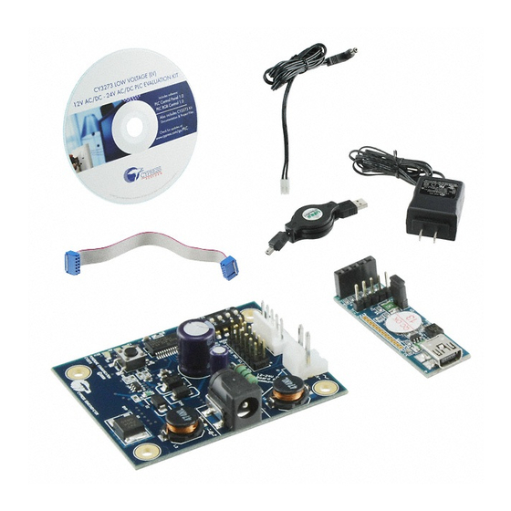
Page 7: Kit Contents
■ 1.3.1 Additional Requirements The following Cypress Demonstration Kit is used in the example applications in this user guide. This kit is available for purchase from http://www.cypress.com. CY3210-PSoCEval1 Kit This PSoC Evaluation Kit features an evaluation board and MiniProg programming unit. The evalua- tion board includes an LCD module, potentiometer, LEDs, and plenty of bread boarding space to meet all your evaluation needs. -
Page 8: Document Revision History
Click the File icon and then click Open. Displays an equation: Times New Roman 2 + 2 = 4 Text in gray boxes Describes cautions or unique functionality of the product. CY3273 Cypress Low Voltage Powerline Communication Evaluation Kit Guide, Doc. # 001-55382 Rev. *A [+] Feedback... -
Page 9: Plc Lv Evaluation Board
Input Voltage: 12/24V AC/DC ■ Input Current: 200 mA/150 mA ■ Operating Temperature: 0°C to 40°C ■ Operating Humidity Condition: 5% to 95% RH, non-condensing ■ CY3273 Cypress Low Voltage Powerline Communication Evaluation Kit Guide, Doc. # 001-55382 Rev. *A [+] Feedback... -
Page 10: Hardware Description
The core of the PLC LV board is the CY8CPLC10 chip. The board contains an I C connector, jump- ers to control various functions, and a five-position DIP switch. CY3273 Cypress Low Voltage Powerline Communication Evaluation Kit Guide, Doc. # 001-55382 Rev. *A [+] Feedback... -
Page 11: Power Supply Circuit
The red, blue, yellow, and green LEDs indicate the different status of the board when functioning. The key components and their use are as follows: CY3273 Cypress Low Voltage Powerline Communication Evaluation Kit Guide, Doc. # 001-55382 Rev. *A [+] Feedback... -
Page 12: Setting Up The Plc Lv Board
J8 is a five pin header that can be used for communicating with an external board, powering an external board, and resetting the CY8CPLC10 device from an external board. A five wire ribbon cable provided with the CY3273 kit can be used to connect to J8. The description for J8 header pins is as follows: CY3273 Cypress Low Voltage Powerline Communication Evaluation Kit Guide, Doc. -
Page 13: Setting Up Manual Addressing On Plc Boards
‘1’ and OFF position for it to be ‘0’. For example for setting Logical address of 0X06 (see Figure S2[5] → OFF = 0 S2[4] → ON = 1 S2[3] → ON = 1 CY3273 Cypress Low Voltage Powerline Communication Evaluation Kit Guide, Doc. # 001-55382 Rev. *A [+] Feedback... -
Page 14: Setting Up I2C Address Of The Node
C addressing, refer to the data sheet available on the CD. 2.4.4 Jumper Settings for the PLC LV Boards Figure 2-3. Six Jumpers Available on Board CY3273 Cypress Low Voltage Powerline Communication Evaluation Kit Guide, Doc. # 001-55382 Rev. *A [+] Feedback... - Page 15 When the jumper is connected, the SCL line will get pulled high. This needs to be done when the user wants the I2C link to be pulled up by the CY3273 board. This jumper does not need to be placed if the USB-I2C bridge is used for communication to the host.
- Page 16 PLC LV Evaluation Board CY3273 Cypress Low Voltage Powerline Communication Evaluation Kit Guide, Doc. # 001-55382 Rev. *A [+] Feedback...
-
Page 17: Appendix
Appendix Schematics A.1.1 Board Overview CY3273 Cypress Low Voltage Powerline Communication Evaluation Kit Guide, Doc. # 001-55382 Rev. *A [+] Feedback... -
Page 18: User Interface
A.1.2 User Interface CY3273 Cypress Low Voltage Powerline Communication Evaluation Kit Guide, Doc. # 001-55382 Rev. *A [+] Feedback... -
Page 19: Transmit And Receive Filters
A.1.3 Transmit and Receive Filters CY3273 Cypress Low Voltage Powerline Communication Evaluation Kit Guide, Doc. # 001-55382 Rev. *A [+] Feedback... -
Page 20: Power Supply
A.1.4 Power Supply CY3273 Cypress Low Voltage Powerline Communication Evaluation Kit Guide, Doc. # 001-55382 Rev. *A [+] Feedback... -
Page 21: Layout
Layout A.2.1 Top Layer CY3273 Cypress Low Voltage Powerline Communication Evaluation Kit Guide, Doc. # 001-55382 Rev. *A [+] Feedback... -
Page 22: Ground Layer
A.2.2 Ground Layer CY3273 Cypress Low Voltage Powerline Communication Evaluation Kit Guide, Doc. # 001-55382 Rev. *A [+] Feedback... -
Page 23: Power Layer
A.2.3 Power Layer CY3273 Cypress Low Voltage Powerline Communication Evaluation Kit Guide, Doc. # 001-55382 Rev. *A [+] Feedback... -
Page 24: Bottom Layer
A.2.4 Bottom Layer CY3273 Cypress Low Voltage Powerline Communication Evaluation Kit Guide, Doc. # 001-55382 Rev. *A [+] Feedback... -
Page 25: Top Silkscreen
A.2.5 Top Silkscreen CY3273 Cypress Low Voltage Powerline Communication Evaluation Kit Guide, Doc. # 001-55382 Rev. *A [+] Feedback... -
Page 26: Bottom Silkscreen
A.2.6 Bottom Silkscreen CY3273 Cypress Low Voltage Powerline Communication Evaluation Kit Guide, Doc. # 001-55382 Rev. *A [+] Feedback... -
Page 27: Bill Of Materials
LITE-ON (0805) C170KGKT LED, SUPER RED CLEAR, SMD, LTST- 160-1415-1- LITE-ON 2012 (0805) C170KRKT LED, CLEAR YELLOW, SMD, 2012 LTST- 160-1416-1- LITE-ON (0805) C170KSKT CY3273 Cypress Low Voltage Powerline Communication Evaluation Kit Guide, Doc. # 001-55382 Rev. *A [+] Feedback... - Page 28 CT-ND R13, R23, RESISTOR, 10.0K, 1%, 1/10W, 0603 MCR03EZPFX RHM10.0KH R33, R43, ROHM 1002 CT-ND RESISTOR, 402, 0603, 1%, 1/10W, MCR03EZPFX RHM402HCT ROHM 4020 CY3273 Cypress Low Voltage Powerline Communication Evaluation Kit Guide, Doc. # 001-55382 Rev. *A [+] Feedback...
- Page 29 CRYSTAL 32.768KHZ 12.5PF, CYL- 32.768 ECS-3X8X X1123-ND INDER, SERIES ECS-31X OSC 24.000MHZ 5.0V +/-100PPM 24.00 C3290- Crystek C3290-24.000 24.000-ND Y2 (2nd CSX750FCC2 300-7214-2- Citizen source) 4.000M-UT CY3273 Cypress Low Voltage Powerline Communication Evaluation Kit Guide, Doc. # 001-55382 Rev. *A [+] Feedback...
- Page 30 CY3273 Cypress Low Voltage Powerline Communication Evaluation Kit Guide, Doc. # 001-55382 Rev. *A [+] Feedback...
Need help?
Do you have a question about the CY3273 and is the answer not in the manual?
Questions and answers