Table of Contents

Related Manuals for Cypress CapSense Express SmartSense CY3280-MBR2


Summary of Contents for Cypress CapSense Express SmartSense CY3280-MBR2
- Page 1 ® CY3280-MBR2 CapSense Express™ with SmartSense™ Auto-Tuning Kit Guide Doc. # 001-71857 Rev. *C Cypress Semiconductor 198 Champion Court San Jose, CA 95134-1709 Phone (USA): 800.858.1810 Phone (Intnl): 408.943.2600 http://www.cypress.com...
- Page 2 Cypress Source Code and derivative works for the sole purpose of creating custom soft- ware and or firmware in support of licensee product to be used only in conjunction with a Cypress integrated circuit as speci- fied in the applicable agreement.
-
Page 3: Table Of Contents
Contents 1. Introduction Kit Contents .........................5 Factory Default Configuration ..................5 Reference Documents ....................5 Acronyms........................6 Document Revision History ..................6 Documentation Conventions ..................6 2. Getting Started Before you Begin ......................9 Installation Procedure ....................9 3. Kit Operation CY8CMBR2110 CapSense Controller Features............14 3.1.1 Configuring CY8CMBR2110 CapSense Controller ........14 Kit Features .......................16 3.2.1 SmartSense Auto-Tuning ................16 3.2.2 Toggle (Touch ON/OFF) .................18... - Page 4 Contents 3.2.10 Button Controlled LED Effects ............... 26 3.2.10.1 Enable Button Controlled LED Effects..........26 3.2.10.2 Test CapSense Buttons with Button Controlled LED Effects ..26 3.2.11 System Diagnostics ..................27 3.2.11.1 Enable System Diagnostics ............. 27 3.2.11.2 Test System Diagnostics - CapSense Button Short to Ground ..27 3.2.11.3 Test System Diagnostics - CapSense Button to Button Short..
-
Page 5: Introduction
This guide provides details on the kit contents, installation procedure, hardware descriptions, sample configurations, schematics, and the bill of materials. The kit package includes the EZ-Click customizer tool, which is required to configure the kit. For more information and to download the tool, visit http://www.cypress.com/go/ez-click. Kit Contents CY3280-MBR2 kit ■... -
Page 6: Acronyms
Introduction Acronyms Acronym Definition Simple Button Module CapSense Sigma-Delta Electrostatic Discharge Graphic User Interface Inter Integrated Circuit Light Emitting Diode Mechanical Button Replacement Not Connected Printed Circuit Board Personal Computer Universal Serial Bus Document Revision History Table 1-1. Revision History Revision PDF Creation Origin of Description of Change... - Page 7 Introduction Table 1-2. Document Conventions for Guides Convention Usage Represents menu paths: File > Open File > Open > New Project Displays commands, menu paths, and icon names in procedures: Bold Click the File icon and then click Open. Displays an equation: Times New Roman 2 + 2 = 4 Text in gray boxes...
- Page 8 Introduction CY3280-MBR2 CapSense Express with SmartSense Auto-Tuning Kit Guide, Doc. # 001-71857 Rev. *C...
-
Page 9: Getting Started
This chapter describes the installation of the CY3280-MBR2 CapSense Express with SmartSense Auto-Tuning Kit. Before you Begin All Cypress software installations require administrator privileges, but this is not required to run the installed software. 1. Shut down any Cypress software that is currently running. - Page 10 Getting Started Figure 2-1. Kit Installer Startup Screen Note If auto-run does not execute, double-click cyautorun.exe file on the root directory of the CD/DVD, as shown in Figure 2-2. To access the root directory, click Start > My Computer > CY3280-MBR2 <drive:>.
- Page 11 Getting Started Figure 2-3. InstallShield Wizard 6. On the Product Installation Overview screen, select the installation type that best suits your requirement. The drop-down menu has three options: Typical, Complete, and Custom, as shown in Figure 2-4. If you are uncertain, proceed with the default setting (Typical). 7.
- Page 12 Getting Started Figure 2-5. Installation Page 10.Click Finish to complete the installation. Figure 2-6. Installation Complete CY3280-MBR2 CapSense Express with SmartSense Auto-Tuning Kit Guide, Doc. # 001-71857 Rev. *C...
-
Page 13: Kit Operation
Kit Operation The CY8CMBR2110 CapSense controller supports multiple features. The CY3280-MBR2 CapSense Express Kit package includes the hardware required to demonstrate these features. This chapter details these features along with how to use them with the kit. To start using the kit, open the case using the screw driver and insert the two AAA batteries in the battery holder. -
Page 14: Cy8Cmbr2110 Capsense Controller Features
1. Connect the CY3280-MBR2 kit to the PC via the USB port using the USB cable and move the switch position to GUI. Ensure USB Status LED glows. 2. Open the EZ-Click customizer tool from the default location: Start > All Programs > Cypress > EZ-Click <version> > EZ-Click. - Page 15 Kit Operation 5. Connect the kit to the EZ-Click tool using the following steps. a. Click on the Connect button on the Main Console tab of the EZ-Click customizer tool. The EZ-Click will throw an error as shown. Click OK on the pop-up window. Ensure USB Power LED glows.
-
Page 16: Kit Features
Kit Operation Kit Features The following sections demonstrate each feature of this device. 3.2.1 SmartSense Auto-Tuning The CY8CMBR2110 CapSense controller is built with a robust CSD capacitive sensing method and patented SmartSense auto-tuning algorithm. SmartSense Auto-Tuning tunes each sensor automatically at power up; it then monitors and maintains optimum sensor performance during run time. - Page 17 Flex-PCB. BSM board is not provided as part of this kit. To purchase or know more about BSM board, refer to the Cypress website. The Flex-PCB needs to be disconnected from the kit to test the features mentioned in the subsequent sections.
-
Page 18: Toggle (Touch On/Off)
Kit Operation c. Apply the configuration to the kit by following step 7-9. d. Verify the feature as explained in the sections 3.2.2 to 3.2.10. Ensure that you have a new project every time you verify a different feature. Enabling two or more features may or may not work at the same time. -
Page 19: Flanking Sensor Suppression (Fss)
Kit Operation Figure 3-5. Toggle (Touch ON/OFF) Enabled Button LED glows on touch Button is “on” even after Button goes “off“ on second touch touch is removed 3.2.3 Flanking Sensor Suppression (FSS) 3.2.3.1 Enable Flanking Sensor Suppression Go to the Device Config tab; select the Flanking Sensor Suppression checkbox to enable the FSS feature for the desired number of buttons. -
Page 20: Led On Time
Kit Operation Figure 3-7. FSS Enabled Second button does not glow if Second button glows after the Button LED glows on touch the touch on the first button finger from the first touched is continued button is removed 3.2.4 LED ON Time 3.2.4.1 Enable LED ON Time Go to the Visual Config tab;... -
Page 21: Button Auto Reset (Arst)
Kit Operation Figure 3-9. LED ON Time Enabled Button is “on” even after Button goes “off” after the Button LED glows on touch touch is removed LED On time 3.2.5 Button Auto Reset (ARST) 3.2.5.1 Enable Button Auto Reset Go to the Device Config tab; select the Auto reset period menu to enable this feature. The reset time can be set as either 5 or 20 seconds. -
Page 22: Debounce Control
Kit Operation Figure 3-11. ARST Enabled Button LED glows on touch Button goes off when continuously touched for more than the ARST 3.2.6 Debounce Control 3.2.6.1 Enable Debounce Control Go to the Device Config tab; enter the required debounce number in the Debounce menu. Enter a value from 1 to 255 in the option available for CS0 and CS1-CS9. -
Page 23: Buzzer Signal Output
Kit Operation Figure 3-13. Debounce Enabled Button does not glow if pressed for less than the time set in the Debounce parameter settings 3.2.7 Buzzer Signal Output 3.2.7.1 Enable Buzzer Signal Output Go to the Device Config tab; enable the feature by selecting the Buzzer checkbox in the Buzzer Configuration section of the page. -
Page 24: Host Controlled Gpos
Kit Operation 3.2.8 Host Controlled GPOs 3.2.8.1 Drive Host Controlled GPOs Go to the Device Config tab; drive host controlled GPOs, HCG1 and HCG2, by selecting the Low or High options in the drop-down. The kit does not have any LEDs mapped to HCG3 and HCG4. These GPOs use the same pins as the buzzer output. -
Page 25: Power-On Led Effects
Kit Operation 3.2.9 Power-On LED Effects 3.2.9.1 Enable Power-On LED Effects Go to the Visual Config tab; select the At Power On checkbox under LED Effects to enable the feature. Select the values for different parameters such as ramp up time, ramp down time, high time, low time, high brightness, low brightness, and LED effect repeat rate in the At Power On tab. -
Page 26: Button Controlled Led Effects
Kit Operation - Ramp up time - High brightness time - Ramp down time - Low brightness time 3.2.10 Button Controlled LED Effects 3.2.10.1 Enable Button Controlled LED Effects Go to the Visual Config tab; select the On Button Touch checkbox under LED Effects to enable the feature. -
Page 27: System Diagnostics
Kit Operation Figure 3-20. Button Controlled LED Effects Pattern 3.2.11 System Diagnostics 3.2.11.1 Enable System Diagnostics The System Diagnostics feature is enabled in the CY8CMBR2110 CapSense controller by default; no change is needed in the kit. This feature sends out a 5-ms pulse on the GPO corresponding to a faulty sensor. -
Page 28: Test System Diagnostics - Capsense Button To Button Short
Kit Operation To observe the feature in GUI, go to Production line testing tab and click on the Start test button. Figure 3-22. System Diagnostics GUI - Shorting Button to Ground 3.2.11.3 Test System Diagnostics - CapSense Button to Button Short Follow these steps: 1. -
Page 29: Test System Diagnostics - Capsense Button To Vdd Short
Kit Operation Figure 3-24. System Diagnostics GUI - Shorting Button to Button 3.2.11.4 Test System Diagnostics - CapSense Button to Vdd Short Follow these steps: 1. Touch the power button to turn off the kit. 2. Connect a wire between pin #27 and pin #41 of the 44-pin expansion connector. This shorts but- ton #6 sensor with Vdd. - Page 30 Kit Operation Figure 3-26. System Diagnostics GUI - Shorting Button to Vdd CY3280-MBR2 CapSense Express with SmartSense Auto-Tuning Kit Guide, Doc. # 001-71857 Rev. *C...
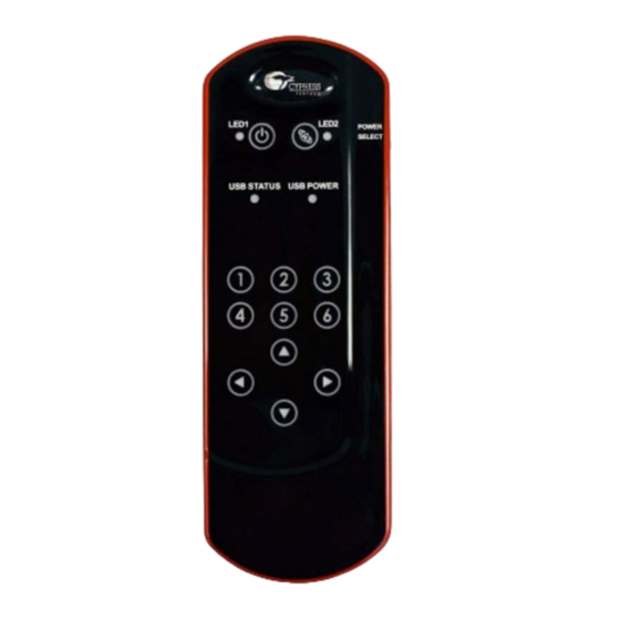
- Page 31 Hardware The CY3280-MBR2 CapSense Express Kit is designed to demonstrate the features of the CY8CMBR2110 register configurable CapSense controller. Figure 3-1 on page 13 illustrates ten CapSense buttons and CapSense-based power and attention buttons. The kit has two status LEDs to demonstrate the direct LED control feature.
-
Page 32: Power Block
Hardware Figure 4-2 shows the block diagram of the CY3280-MBR kit. The block diagram can be classified into four sections: Power, CY8CMBR2110 functional blocks, I2C to USB, and Connectors (USB-IIC and 44-pin expansion connector). Each section is explained in detail here. Figure 4-2. -
Page 33: Cy8Cmbr2110 Functional Block
Hardware Figure 4-3. Power Supply System Structure Schematic VDD_BAT VDD_USB VDD_Ext VDD_SW MBR0520L 0.1 uFd 0603 0805 VOUT SP4T Zero E 665 E PWR_ON VDD_Dev VDD_SW 0.1uf PWR_ON_INV GND1 Battery Clip AAA 0805 Zero E PWR_ON_INV 1206 10 uFd 16v SN74LVC1GU04 LED Red 1206... -
Page 34: Connector Details
Hardware Connector Details 4.4.1 USB-IIC Connector This kit is configurable through the IIC interface. The USB-IIC connector enables the kit to connect to the PC via the USB cable provided with the kit. This connector serves two main purposes: Enables powering the kit from the GUI ■... -
Page 35: Sample Configurations
1. Connect the CY3280-MBR2 kit to the PC via the USB port using the USB cable and move the switch position to GUI. Ensure USB Status LED glows. 2. Open the EZ-Click customizer tool from the default location: Start > All Programs > Cypress > EZ-Click <version> > EZ-Click. - Page 36 Sample Configurations 4. Navigate to the project directory <Install_Directory>:\Program Files\Cypress\ CY3280-MBR2\<version>\Sample Configurations\Sample Configuration 1 in the Open Project - Select Project Location window. 5. Double-click on the Sample Configuration 1 file to open. Figure 5-2. Open Configuration1 File 6. Connect the kit to the EZ-Click tool using the following steps.
-
Page 37: Loading Configuration File 2
The GUI images for the following steps are similar to 5.1.1 Loading Configuration File 1 on page 1. Steps 1 to 3 remains the same as mentioned 5.1.1. 2. Navigate to the project directory <Install_Directory>:\Program Files\Cypress\ CY3280-MBR2\<version>\Sample Configurations\Sample Configuration 2 in the Open Project - Select Project Location window. -
Page 38: Loading Configuration File 3
The GUI images for the following steps are similar to 5.1.1 Loading Configuration File 1 on page 1. Steps 1 to 3 remains the same as mentioned 5.1.1. 2. Navigate to the project directory <Install_Directory>:\Program Files\Cypress\ CY3280-MBR2\<version>\Sample Configurations\Sample Configuration 3 in the Open Project - Select Project Location window. -
Page 39: Schematics
Appendix Schematics A.1.1 CY3280-MBR2 Board VDD_BAT VDD_USB VDD_Ext VDD_SW MBR0520L 0.1 uFd 0603 0805 VOUT SP4T Zero E 665 E PWR_ON VDD_Dev VDD_SW 0.1uf PWR_ON_INV GND1 Battery Clip AAA 0805 Zero E 1206 PWR_ON_INV 10 uFd 16v SN74LVC1GU04 LED Red 1206 10 uFd 16v MIC94090 SC-70-6... - Page 40 VDD_Dev Sensor VDD_Ext CapSense Button 8mm Round GPO0 0805 VDD_Dev VDD_Ext 1206R VDD_Dev 665 E LED Red TVS3 .20A FUSE 5V 350W GPO1 0805 1206 10 uFd 16v 1206R Sensor 665 E CapSense Button 8mm Round I2CSDA I2CSCL LED Red 0.1uf GPO2 0805...
- Page 41 A.1.2 Flex-PCB Flex_BTN8 Flex_BTN5 Flex_BTN2 Flex_BTN9 Flex_BTN7 Flex_BTN4 Flex_BTN1 Flex_BTN6 Flex_BTN3 Flex_BTN0 VDD_Dev 22x2_RA_Header 22x2_RA_Header Flex_BTN8 Flex_BTN5 CapSense Button CSB15_92X7_96OBL_1MM CapSense Button CSB15_92X7_96OBL_1MM Sensor Sensor Sensor Sensor CapSense Button CSB_10MM_RND_2MM CapSense Button CSB_10MM_RND_2MM Flex_BTN9 Flex_BTN2 CapSense Button CSB13_26X6_63_OBL_1MM CapSense Button CSB13_26X6_63_OBL_1MM Sensor Sensor Sensor...
-
Page 42: Board Layouts
Board Layouts A.2.1 CY3280-MBR2 Board Primary Side CY3280-MBR2 CapSense Express with SmartSense Auto-Tuning Kit Guide, Doc. # 001-71857 Rev. *C... - Page 43 A.2.2 CY3280-MBR2 Board Secondary Side CY3280-MBR2 CapSense Express with SmartSense Auto-Tuning Kit Guide, Doc. # 001-71857 Rev. *C...
- Page 44 A.2.3 Power Layer CY3280-MBR2 CapSense Express with SmartSense Auto-Tuning Kit Guide, Doc. # 001-71857 Rev. *C...
- Page 45 A.2.4 Ground Layer CY3280-MBR2 CapSense Express with SmartSense Auto-Tuning Kit Guide, Doc. # 001-71857 Rev. *C...
- Page 46 A.2.5 Flex-PCB Primary Side A.2.6 Flex-PCB Secondary Side CY3280-MBR2 CapSense Express with SmartSense Auto-Tuning Kit Guide, Doc. # 001-71857 Rev. *C...
-
Page 47: Bill Of Materials (Bom)
Bill of Materials (BOM) Item Reference Description Manufacturer Mfr Part Number CAP .10UF 10V CERAMIC X7R C2,C1,C6,C12,C7 Kemet C0603C104K8RACTU 0603 CAP CERAMIC 10.0UF 16V C3,C4 Kemet C1206C106K4PACTU X5R 1206 CAP CER 2200PF 50V 5% C0G Murata Electronics North GRM2165C1H222JA01D 0805 America CAP 1.0UF 16V CERAMIC Y5V Murata Electronics North... - Page 48 Micrel Inc MIC94090YC6 TR SC70-6 IC SINGLE INVERTER GATE Texas Instruments SN74LVC1GU04DBVR SOT-23-5 IC MCU CAPSENSE QFN16 Cypress Semiconductor CY8CMBR2044-24LKXI IC LDO REG 1A SOT223-6 Texas Instruments TPS73701DCQ IC PSOC 16KB FLASH 56QFN Cypress Semiconductor CY8C24894-24LFXA IC SINGLE USB PORT TVS...
Need help?
Do you have a question about the CapSense Express SmartSense CY3280-MBR2 and is the answer not in the manual?
Questions and answers