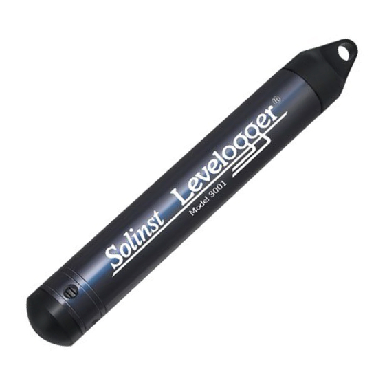
Solinst Levelogger Series User Manual
Hide thumbs Also See for Levelogger Series:
Table of Contents

Advertisement

User Guide
Levelogger Series
September 1, 2020

Advertisement

Table of Contents
loading
Need help?

Need help?

Do you have a question about the Levelogger Series and is the answer not in the manual?

Questions and answers

Summary of Contents for Solinst Levelogger Series

  • Page 1 User Guide Levelogger Series September 1, 2020...
  • Page 2 © 2020 Solinst Canada Ltd. All rights reserved. Printed in Canada. Solinst and Levelogger are registered trademarks of Solinst Canada Ltd. All other trademarks and registered trademarks are the property of their respective owners.
  • Page 3: Table Of Contents

    Levelogger Series User Guide - Table of Contents 1 Introduction 1.1 Levelogger Series 1.1.1 Levelogger 5 1.1.2 Barologger 5 1.1.3 Levelogger 5 Junior 1.1.4 Levelogger 5 LTC 1.1.5 Rainlogger 5 1.1.6 Levelogger Edge 1.1.7 Barologger Edge 1.1.8 Levelogger Junior Edge 1.1.9 LTC Levelogger Edge...
  • Page 4 Levelogger Series User Guide - Table of Contents 6 Conductivity Calibration 6.1 Restore Factory LTC Levelogger Calibration 7 Data Control 7.1 Downloading Options and Saving Data Files 7.1.1 Default File Format 7.1.2 Downloading Data 7.1.3 Saving Data 7.2 Graph Manipulation and Zoom Function 7.3 File Export and Print Function...
  • Page 5: Introduction

    Solinst dataloggers can also be used with the Solinst Levelogger App, which shares most of the features of Solinst Levelogger 4.5 Software, on your smart device. To use the Solinst Levelogger 5 App Interface, see the separate User Guide.
  • Page 6: Levelogger Series

    Water levels are displayed as temperature compensated pressure readings, and can be barometrically compensated with the aid of a Barologger 5. Note: Solinst recommends using the most recent Levelogger 5 firmware version with the latest Levelogger Software version. See Section 2.3.
  • Page 7 The Barologger 5 uses algorithms based on air pressure only. It measures and logs changes in atmospheric pressure and temperature, which are then used to compensate water level readings recorded by a Levelogger. Note: Solinst recommends using the most recent Barologger 5 firmware version with the latest Levelogger Software version. See Section 2.3.
  • Page 8: Levelogger 5 Junior

    The Levelogger 5 Junior provides an inexpensive alternative for measuring groundwater and surface water levels and temperature. Note: Solinst recommends using the most recent Levelogger 5 Junior firmware version with the latest Levelogger Software version. See Section 2.3. Levelogger 5 Junior Technical Specifications...
  • Page 9: Levelogger 5 Ltc

    The Levelogger 5 LTC provides an accurate and convenient method to measure water level, temperature and conductivity all in one probe. Note: Solinst recommends using the most recent Levelogger 5 LTC firmware version with the latest Levelogger Software version. See Section 2.3.
  • Page 10 Note: Solinst recommends using the most recent Rainlogger 5 firmware version with the latest Levelogger Software version. See Section 2.3.
  • Page 11: Levelogger Edge

    Water levels are displayed as temperature compensated pressure readings, and can be barometrically compensated with the aid of a Barologger. Note: Solinst recommends using the most recent Levelogger Edge firmware version with the latest Levelogger Software version. See Section 2.3.
  • Page 12: Barologger Edge

    The Barologger Edge uses algorithms based on air pressure only. It measures and logs changes in atmospheric pressure and temperature, which are then used to compensate water level readings recorded by a Levelogger. Note: Solinst recommends using the most recent Barologger Edge firmware version with the latest Levelogger Software version. See Section 2.3.
  • Page 13: Levelogger Junior Edge

    The Levelogger Junior Edge provides an inexpensive alternative for measuring groundwater and surface water levels and temperature. Note: Solinst recommends using the most recent Levelogger Junior Edge firmware version with the latest Levelogger Software version. See Section 2.3. Levelogger Junior Edge Technical Specifications...
  • Page 14: Ltc Levelogger Edge

    The LTC Levelogger Edge provides an accurate and convenient method to measure water level, temperature and conductivity all in one probe. Note: Solinst recommends using the most recent LTC Levelogger Edge firmware version with the latest Levelogger Software version. See Section 2.3.
  • Page 15: Rainlogger Edge

    (based on rainfall calibration constant). Note: Solinst recommends using the most recent Rainlogger Edge firmware version with the latest Levelogger Software version. See Section 2.3. Rainlogger Edge Technical Specifications...
  • Page 16: Measurement Parameters

    Levelogger Series User Guide 1.2 Measurement Parameters 1.2.1 Level All Leveloggers measure total (absolute) pressure. When submerged, the Levelogger is recording the combination of barometric pressure and water pressure. The actual pressure of just water ( ) above the sensor is...
  • Page 17: Temperature

    LTC Levelogger is being set up for its initial use and after long periods of dry storage. 1.2.5 Total Rainfall Solinst Rainloggers are designed to record the number of tips of an external tipping-bucket rain gauge, and output the amount of rainfall per tip.
  • Page 18: Communicating With Solinst Dataloggers

    Levelogger Series User Guide 2 Communicating with Solinst Dataloggers Levelogger Software is Windows based, and is therefore used with a desktop or laptop PC. Dataloggers connect to a PC with an Optical Reader or PC Interface Cable. The Optical Readers and PC Interface Cable use an optical data reader/port connected to the datalogger and a USB (or RS-232 Serial Com Port) to transfer information between the datalogger and computer.
  • Page 19 Levelogger Series User Guide You can also use an older style Optical Reader with an L5–Edge DRC Adaptor to communicate with a 5 Series datalogger. Note: The L5–Edge DRC Adaptor contains a small, long-lasting battery (not user-replaceable). The Adaptor should always be stored above freezing temperatures and with caps on to prevent unnecessary battery drainage and protect the optical eyes.
  • Page 20 Levelogger Series User Guide Field Reader 5 and Adaptor Edge–L5 DRC Adaptor Figure 2-5 Levelogger Edge Connected to a PC Using an Edge–L5 DRC Adaptor and Field Reader 5 Older Style Optical Reader Figure 2-6 Levelogger Edge Connected to a PC Using an Older Style Optical Reader...
  • Page 21: Pc Interface Cable

    Levelogger Series User Guide 2.2 PC Interface Cable If a datalogger is deployed in the field using a L5 Direct Read Cable (or older style Direct Read Cable), a PC Interface Cable connects to the L5 Direct Read Cable for communication with the PC—no need to remove the datalogger from the well.
  • Page 22: Backwards Compatibility

    5 Junior, Levelogger 5 LTC, and the Rainlogger 5. Note: It is always recommended to use the most recent version of software and firmware. Let Solinst keep you up-to-date with each new software and firmware release. Register your software at: www.solinst.com/Registration/ to receive these updates.
  • Page 23: System Requirements And Software Installation

    3) The Software Installation Wizard will guide you through the remaining installation process. Figure 3-1 shows the Levelogger Installation Wizard. 4) Restart the computer after installation is completed. Default Directory is C:\Program Files\Solinst\Levelogger4_5 Figure 3-1 Software Installation Wizard Page 23...
  • Page 24: Startup, Configurations And Settings

    Note: You can also check for updates using the Help menu. 4.1.2 Communicating with a USB Port There are two types of Solinst USB devices that you can use to communicate with Levelogger Software: 1) Older style Optical Readers (received before February 2018) and PC Interface Cables (received before July 2018) that sometimes require updating drivers.
  • Page 25: Older Style Usb Devices

    Levelogger Software Installation Wizard also copies a folder to the Levelogger folder containing all the Solinst USB drivers. When you plug in the Solinst USB device, check the Com Port designation after the device is installed. Note: to check the Com Port assigned to these USB devices after installation, open the Device Manager. Expand “Ports (COM &...
  • Page 26: Configuration And Settings

    Levelogger Series User Guide 4.2 Configuration and Settings 4.2.1 Data Directory Levelogger Software program will save data downloaded to the following default directory: <C:\Program Files\Solinst\Levelogger4_5\Data> Unless otherwise specified in the Default Directory field of the Application Settings window (Figure 4-1).
  • Page 27: Levelogger Series Setup

    5 Levelogger Series Setup Depending on the type of datalogger, there will be differences in programming options, memory, and battery life. See below for a summary of the differences: Table 5–1: Levelogger Series Programming Options. Memory & Battery Life Datalogger Type Sampling Options...
  • Page 28: Datalogger Settings

    Levelogger Series User Guide After you start the Levelogger Software, the main Levelogger Software window will appear, with the Datalogger Settings tab open. Note: Click on icons to get an explanation of that software feature. Figure 5-1 Datalogger Settings Tab Select the appropriate Com Port for the connected communications device from the centre drop-down menu.
  • Page 29: Setting Up Channel Information

    Levelogger Series User Guide 5.1.1 Setting Up Channel Information In the lower left portion of the Datalogger Settings tab is the area for setting channel parameters (level, temperature, conductivity, rainfall). The Levelogger Software will detect the available channels when the datalogger settings are retrieved.
  • Page 30: Conductivity Channel (Ch3)

    Levelogger Series User Guide 5.1.1.3 Conductivity Channel (Ch3) • Identification describes the measurement parameter of the channel and has already been configured as 'CONDUCTIVITY'. The channel can be re-named to suit each project. The Identification field will be the channel heading, data column heading and graph line name when viewing the data.
  • Page 31: Rainloggers

    Levelogger Series User Guide 5.1.1.4 Rainloggers There is one channel of measurement for a Rainlogger. The RainFall Channel records each tip time by the connected tipping-bucket and outputs the amount of rainfall per tip (input Rainfall Cal Constant). • Identification describes the measurement parameter of the channel and has already been configured as 'RainFall'.
  • Page 32: Datalogger Information

    Click Yes to synchronize the clock. It can be very useful to synchronize the clocks of all the Solinst Leveloggers and Barologgers when it comes to Barometric Compensation, especially when being used in the same project.
  • Page 33: Datalogger Sampling Mode

    Levelogger Series User Guide 5.5 Datalogger Sampling Mode The Datalogger Sampling Mode section allows you to choose the sampling measurement type. Options are Linear, Event Based and Schedule. Note: See Table 5-1 for model specific programming options. Linear refers to a set time interval between collection of readings. Sample Rate can be any number from 0.125 seconds to 99 hours for the Levelogger 5.
  • Page 34: Datalogger Memory Mode

    Levelogger Series User Guide Schedule Sampling allows you to select a logarithmic style sampling schedule adapted to the needs of each application. Schedule Sampling is set by using the plus and minus buttons to add or subtract line items in the Schedule window.
  • Page 35: Saving And Retrieving Levelogger Settings Files

    Levelogger Series User Guide 5.7 Saving and Retrieving Levelogger Settings Files To store settings as defaults, click . It will store the settings of the Levelogger into an *.dtf file as a series of defaults. The *.dtf file will save the Project ID, Location, Sample Mode, Sample Rate, Channel ID, Unit, and Offset.
  • Page 36: Starting And Stopping The Datalogger

    Levelogger Series User Guide 5.8 Starting and Stopping the Datalogger Starting the Solinst Datalogger There are two ways to start logging: Start Now or by programming a Future Start time. To start logging immediately, do not click the Future Start box and click, .
  • Page 37 Levelogger Series User Guide Figure 5-14 Future Start Setting Note: Retrieve the Levelogger settings in order to refresh the status (i.e. when the status changes from Future Start to Started). Note: Using a Future Start to synchronize all of your Loggers to start at the same time is recommended when deploying a Barologger to compensate a number of Leveloggers.
  • Page 38: Conductivity Calibration

    Calibration Wizard. You place the LTC Levelogger in a specified calibration solution and follow the steps provided by the LTC Levelogger Edge wizard. Conductivity calibration solutions are available from Solinst or any laboratory supply outlet. The Levelogger 5 LTC and LTC Edge have a 100,000 µS/cm conductivity range and a calibrated range from 50 to 80,000 µS/cm.
  • Page 39 Stop the LTC Levelogger by clicking Start the Solinst Levelogger Software Calibration Wizard by clicking the Conductivity Cal tab. The wizard will guide you through the calibration process. You can exit the wizard after any step to cancel the calibration session.
  • Page 40 Levelogger Series User Guide 1) Setting the Temperature Coefficient: The default setting for the Temperature Coefficient is 2.00. If the conductivity solution you are using to calibrate the LTC Levelog states a different temperature coefficient on the label, please input that number into the Temperature Coefficient field.
  • Page 41 Use fresh solution for calibration, and immerse the LTC Levelogger. Lightly tap and stir the Solinst LTC Levelogger to remove any bubbles from the sensor. Allow 2-3 minutes to stabilize, then select next to calibrate.
  • Page 42 If a second failure occurs during calibration, a warning message will appear indicating that your probe may still be dirty, or damaged. This may occur if your Solinst LTC Levelogger conductivity sensor has been affected by dirt, mineral build-up, etc., so it no longer responds like it did when it was first factory calibrated. This step allows your sensor to be calibrated within a wider range of the standard solution value.
  • Page 43: Restore Factory Ltc Levelogger Calibration

    If a third calibration error occurs, or the results of the calibration are outside the error tolerance range, a warning message will appear asking you to contact Solinst for more options (Figure 6-9). Figure 6-9 Levelogger Conductivity Calibration Warning 3 6.1 Restore Factory LTC Levelogger Calibration...
  • Page 44: Data Control

    Levelogger Series User Guide 7 Data Control (Downloading and Viewing Data) Click the Data Control tab on the Main window. From the Data Control tab you can download data from a Levelogger, display data in tabular or graphic format, and save and export data files.
  • Page 45: Downloading Options And Saving Data Files

    Levelogger Series User Guide Figure 7-2 Rainlogger Data When you view data downloaded from a Rainlogger, the RainFall data will be shown in a table and in a bar graph. A drop-down menu appears that allows you to select the time interval at which you would like the data shown, from 1 to 99 seconds, minutes, hours, days, or weeks (this acts like a zoom function).
  • Page 46: Downloading Data

    Levelogger Series User Guide 7.1.2 Downloading Data Note: Before downloading data you must select the Com Port that the datalogger is connected to and retrieve the settings from the attached datalogger by clicking in Datalogger Settings tab. Click from the Data Control tab to download data from a connected datalogger. There are four options for downloading data.
  • Page 47: Saving Data

    Levelogger Series User Guide For Levelogger 5 Series dataloggers, if you select Download Files, the software will bring up a window with a list of logging sessions currently stored in the datalogger’s memory. Select the files you want to download.
  • Page 48: Graph Manipulation And Zoom Function

    Levelogger Series User Guide 7.2 Graph Manipulation and Zoom Function To perform the Zoom In function on the graph, click To perform a Zoom Out function on the graph click . Click to undo all the zoom functions. The Zoom functions can also be used for data selections in the graph.
  • Page 49 Levelogger Series User Guide The Title and Axis Option is used to enter the title of the graph and change the Y axis label or user selected scale. Check the Best Fit box to enable the software to determine the best fit scale. If the Best Fit box is not checked, the user has to enter a maximum and minimum value of the selected channel.
  • Page 50 Levelogger Series User Guide There is also the option to view more than one graph at a time. Click and drag a File Name Tab and drop it when you see a shaded area on the window to open a separate graph of that data file. You can view any number of graphs at one time by re-sizing your window as required.
  • Page 51: File Export And Print Function

    Levelogger Series User Guide 7.3 File Export and Print Function Data can be exported in *.csv (comma separated value) file format or *.xml (extensible markup language) file format by clicking File > Export > Data or The *.csv and *.xml file formats are supported and can be imported by most spreadsheet and database programs.
  • Page 52: Data Compensation

    8.1 Data Wizard Open the Solinst Levelogger Software Data Wizard tab. The first step is to select your Data Compensation Path. The choices for Leveloggers are Basic or Advanced. Choosing Basic allows you to do a simple Barometric Compensation of Levelogger data only.
  • Page 53 Levelogger file to be offset by that amount. It is recommended to stay with the default zero value, unless a known offset has been determined (e.g. to correct for pressure sensor drift. See Solinst Technical Bulletin: Understanding Pressure Sensor Accuracy, Precision, Resolution & Drift: https://www.solinst.com/onthelevel-news/water-level-monitoring/water-level-datalogging/ understanding-pressure-sensor-accuracy-precision-resolution-drift/.
  • Page 54: Basic Compensation

    Data Control tab. Do not change or delete the file extension. All data files are saved to the default location: <C:\Program Files\Solinst\Levelogger4_5\Data>. Note: The default directory for saved files can be changed by clicking the Configuration menu at the top of the program window, selecting ‘Application Settings’...
  • Page 55 Levelogger Series User Guide The next window will show the results of the compensation. If the compensation was unsuccessful, there will be an explanation in the Reason column (e.g. time stamp of Levelogger and Barologger files were not close enough to perform an accurate compensation). You can still view the compensated file in the Data Control tab by clicking ‘Open’...
  • Page 56: Advanced Compensation

    Levelogger Series User Guide 8.1.2 Advanced Compensation When you select Advanced compensation, the Data Compensation Options window will open. Figure 8-5 Advanced Data Compensation Options First, you will select how you want your data displayed (Manual Data Adjustment): • Height of Water Above Sensor is the default display option. Select this option to perform a Barometric Compensation and/or Parameter Adjustments to one or more data files, while keeping the sensor diaphragm (zero point) as the reference point.
  • Page 57 Levelogger Series User Guide In the next window, you will choose the Levelogger file(s), Rainlogger file(s), and Barologger file(s) you would like to use in the compensation. Any files you have open in the Data Control tab will be listed.
  • Page 58 Levelogger Series User Guide Next, for each selected Levelogger file, you will enter the Field Zero(s) you would like to use to manually adjust your Levelogger data. (If you have selected Height of Water Above the Sensor or Parameter Adjustments Only, this window will not be shown.)
  • Page 59 Levelogger Series User Guide Example 8.1 Depth to Water Level Adjustment When using a manual depth to water measurement taken from the top of a well casing as a Field Zero, enter it as a positive value (e.g. 10 m).
  • Page 60 Levelogger Series User Guide For Elevation of Water Level adjustments, enter a Measuring Point Elevation (A) and a Field Zero (B) from that Measuring Point. If the static water level is below your Measuring Point, the Field Zero is input as a positive value (e.g. if you are using a manual depth to water measurement as a Field Zero, from the top of a well casing as the Measuring Point).
  • Page 61 Data Control tab. Do not change or delete the file extension. All data files are saved to the default location: <C:\Program Files\Solinst\Levelogger4_5\Data>. Note: The default directory for saved files can be changed by clicking the Configuration menu at the top of the program window, selecting ‘Application Settings’...
  • Page 62 Levelogger Series User Guide From the Data Control tab, you can view the data, save the compensated file with a new filename and/or export the data (see Section 7). All the original Levelogger settings and the channel information effective during data collection are shown on the top left of the window.
  • Page 63: Manual Barometric Compensation

    Note: It is important to remember that weather station barometric data will often contain an offset or normalization (i.e. normalization to sea level). Manual data conversation and barometric compensation should account for any variation of the normalization or offset used between the barometric data sourced and Solinst Leveloggers. Note: See our Technical Bulletin:...
  • Page 64: Real Time View

    Levelogger Series User Guide 9 Real Time View Click the Real Time View tab from the main software window (Figure 9-1). The purpose of this tab is to provide on-screen measurement as data is being recorded by the connected datalogger. The data is displayed in tabular and graphical format.
  • Page 65: Installation And Maintenance Of Leveloggers

    Levelogger Series User Guide 10 Installation and Maintenance of Leveloggers 10.1 Installation Many options exist for installation of the Levelogger, but essentially these installation methods can be classified into two broad categories: free suspended or fixed installations. 1) In free suspended installations, the Levelogger is hung via suspension wire/cord or Direct Read Cable from a well cap, or some fixed tie-off location, at the well head.
  • Page 66: Free Suspended Installations

    15 m (50 ft) to 150 m (500 ft), and Kevlar cord assemblies to 150 m (500 ft). Solinst also supplies the Model 3001 2" Well Cap Assembly from which the Levelogger can be suspended.
  • Page 67 Levelogger Series User Guide Follow these steps to install the Levelogger using stainless steel wire and Coil 1 hooks: Coil 3 1) Loop the cable through the coil 2 of the hook assembly, then wind the Coil 2 looped strands several times around the hook shaft and pass through coil 1.
  • Page 68: Direct Read Cable Assembly Installation

    Note: There is also the option to communicate with a DataGrabber 5 or Levelogger 5 App Interface (see separate User Guides). Solinst supplies L5 Direct Read Cable assemblies in lengths up to 1500 ft. The cable has a durable, flexible, abrasion-resistant polyurethane jacket.
  • Page 69 Levelogger Series User Guide Levelogger 5 Series dataloggers can be used with L5 Direct Read Cables, as well as the older style Direct Read Cables (used with Edge and Gold Series dataloggers). To use the older style Direct Read Cables, an L5–Edge DRC Adaptor is required.
  • Page 70 Levelogger Series User Guide Follow these steps to install a Direct Read Cable assembly to a Levelogger 5: 1) Remove the installation cap from the Levelogger, align the optical socket of the L5 Direct Read Cable with the Levelogger and threading the coupling onto the Levelogger tightly (while holding the datalogger still). If using an Adaptor, thread the Adaptor onto the Levelogger first, then thread the Direct Read Cable coupling onto the Adaptor (while holding the Adaptor still).
  • Page 71: Model 3001 Well Cap Assembly

    Levelogger Series User Guide 10.1.1.3 Model 3001 Well Cap Assembly The Model 3001 Well Cap Assembly is designed to fit 2" wells, and provides options for installing Leveloggers with wireline, Kevlar cord, or using a Direct Read Cable. The well cap base provides a tight friction fit onto the well casing. The cap is secured to the base with a twist lock.
  • Page 72: Fixed Installations

    Levelogger Series User Guide 10.1.2 Fixed Installations 10.1.2.1 Flowing Artesian Monitoring Monitoring of flowing artesian conditions using Leveloggers can be quite straight forward. Continuous artesian conditions infer that the piezometric surface never drops below the level of the ground surface, or particularly the top of casing elevation, and the casing is sealed with a wellhead.
  • Page 73: Barologger Installation

    Levelogger Series User Guide 10.1.3 Barologger Installation The Solinst Barologger is a Levelogger with a small range adequate to monitor the fluctuations that occur in barometric pressure. The Barologger’s readings are used to barometrically compensate Levelogger readings. As a rule of thumb, a Barologger can be used to compensate all the Leveloggers in a 30 km (20 mile) radius and/or with every 300 m (1000 ft) change in elevation.
  • Page 74: Rainlogger Installation

    Levelogger Series User Guide 10.1.4 Rainlogger Installation Solinst Rainloggers (Figure 10-19) are designed to log the tip times of an external tipping-bucket rain gauge, and output the amount of rainfall per tip. The Rainlogger 5 and Edge housings are made of ABS, while the Rainlogger housing is made of stainless steel.
  • Page 75: Installation In Extreme Environments

    Figure 10-22 Installation in Freezing Liquid With precautions, the Solinst Levelogger can be used in freezing liquid environments. If monitoring shallow water bodies or groundwater zones susceptible to freezing, the easiest way to avoid transducer damage is to lower the transducer to a point in the water column below the frost line or ice formation depth. In water bodies such as shallow streams, wetlands or ponds where freezing may penetrate to the bottom, install the Levelogger in a vented stilling well imbedded into the bottom of the water body beyond the frost line.
  • Page 76: Marine Or Brackish Installations

    Biofouling on the pressure sensor and conductivity cell can compromise the accuracy of the measurements. A Solinst Biofoul Screen can be used to protect the Levelogger from biofouling. The copper-coiled Delrin screen naturally reduces biofouling, and lengthens the time a Levelogger can be deployed before maintenance is required.
  • Page 77: Levelogger Maintenance

    Levelogger Series User Guide 10.2 Levelogger Maintenance Levelogger maintenance consists of inspecting and replacing o-rings, and cleaning the outside casing, the circulation holes and the optical eye(s). The required frequency of cleaning is dependent on several aspects of the monitored water quality. In freshwater with good to excellent water quality, the Levelogger cleaning requirements will be very minimal;...
  • Page 78 Levelogger optical end more frequently. This could result in damage to the o-rings. These o-rings should be inspected regularly and replaced as required (contact Solinst for replacements). Figure 10-25 Levelogger O-ring Damage Figure 10-26 Replacing Levelogger O-rings To remove the old o-ring, use your fingers to push the o-ring up and roll it off the Levelogger.
  • Page 79: Diagnostics Utility

    Sensor Test, this could mean that you have not calibrated your LTC in a while (~1 year). It is recommended that you perform a conductivity calibration, then ‘Run Diagnostics’ again. If any of these tests fail then a report should be created and emailed to Solinst Technical Support. To execute this function simply click the ‘Run Diagnostics’ button.
  • Page 80: Read Memory Dump

    If creating a report for a LTC Levelogger, the LTC Calibration History Report will be included. Note: The ‘Email Report’ option automatically creates a report and attaches it to an email to send to Solinst—all in one step.
  • Page 81: Email Report

    Clicking Email Report will guide you through the process of creating a Diagnostics Report, and it will automatically attach the report to an email to send to Solinst Technical Staff for troubleshooting. If you are emailing a report for a LTC Levelogger, the LTC Calibration History Report will be included.
  • Page 82: Ltc Calibration History Report

    This function creates a report of all previous user calibrations performed on the LTC Levelogger. Use it to send a history report to Solinst for analysis if the LTC Levelogger readings are irregular and/or the unit does not maintain its calibration. To execute this function simply click the LTC Calibration History Report button.
  • Page 83: Firmware Upgrade Utility

    Levelogger before the upload is finished. Note: Solinst recommends using an Optical Reader (Desktop Reader 5 or Field Reader 5) to connect your Levelogger to the PC during a firmware upgrade to avoid any interruptions during the extended communication period.
  • Page 84: Troubleshooting

    - Ask your System Administrator for assistance. 2) Some files got corrupted during installation of the Levelogger software. Use ‘Add/Remove Programs’ to uninstall then re-install the latest version of Levelogger Software downloaded from the Solinst website Downloads section. 13.2 Error During Software Uninstall Process The ‘Add/Remove Program’...
  • Page 85 2) In Notepad or Wordpad, open the <*.xle> or <*.lls> file to check for corruptions in the file. How are the Levelogger files ended? 3) If problems persist contact Solinst for assistance. ‘Time Span Error, some data cannot be compensated’...
  • Page 86 ‘The selected file is not a barometer’ Select a Barologger for the compensation process. ‘Data Corrupted’ Contact Solinst for assistance. Use Levelogger Diagnostic Utility to do a memory dump and sent the dump file to Solinst for further analysis. ‘Internal Error’...
  • Page 87 ± 10 cm (0.328 ft.) 0.0006% FS Note: Solinst recommends using the most recent Levelogger Gold firmware version with the latest Levelogger Software version. See Section 2.3. Contact Solinst if you need to upgrade your firmware from version 1.016 or lower.
  • Page 88 The Barologger Gold uses algorithms based on air pressure only. It measures and logs changes in atmospheric pressure, which are then used to compensate water level readings recorded by a Levelogger. Note: Solinst recommends using the most recent Barologger Gold firmware version with the latest Levelogger Software version. See Section 2.3.
  • Page 89 The Levelogger Junior provides an inexpensive alternative for measuring groundwater and surface water levels and temperature. Note: Solinst recommends using the most recent Levelogger Junior firmware version with the latest Levelogger Software version. See Section 2.3. Levelogger Junior Technical Specifications...
  • Page 90 The LTC Levelogger Junior provides an accurate and convenient method to measure level, temperature and conductivity all in one probe. Note: Solinst recommends using the most recent LTC Levelogger Junior firmware version with the latest Levelogger Software version. See Section 2.3.
  • Page 91 (based on rainfall calibration constant). Note: Solinst recommends using the most recent Rainlogger firmware version with the latest Levelogger Software version. See Section 2.3. If using a firmware version prior to version 2.000, the Rainlogger will function differently (See previous Levelogger User Guide).
  • Page 92 High Quality Groundwater and Surface Water Monitoring Instrumentation Solinst Canada Ltd. 35 Todd Road, Georgetown, Ontario Canada L7G 4R8 Tel: +1 (905) 873-2255; (800) 661-2023 Fax: +1 (905) 873-1992 instruments@solinst.com...

Table of Contents

Save PDF