Advertisement
Quick Links
1609 Park 370 Pl, Hazelwood, MO 63042
www.pottersignal.com
PAD300-HD
Contents
A. Introduction
E. Addressing
B. Specifications
F. Testing
C. Installation
G. Warranty
D. Locking Feature
A. Introduction
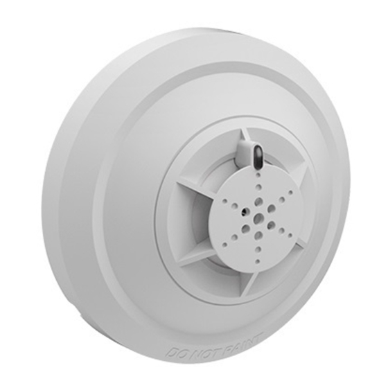
The PAD300-HD is an intelligent addressable thermal detector
with a programmable fixed temperature and a 15oF/min rate
of rise alarm.
Each detector includes one (1) LED to indicate the device
status. The LED flashes momentarily in normal conditions and
flashes at a fast rate when activated. The LED can be turned off
using the programming software.
The PAD300-HD is listed on maximum 70 ft spacing with
alarm set point from 135oF to 185oF on smooth ceiling.
Refer to NFPA 72 for specific information regarding detector
spacing, placement and special applications.
The PAD300-HD communicates on a proprietary protocol to
the addressable fire alarm control panel. It must be connected
to either the IPA series, AFC series, or ARC fire alarm
control panel for proper operation. For detector sensitivity
settings and supervision, please refer to the panel installation
instructions.
Refer to the company website for the latest revision of this
manual.
B. Specifications
Operating Voltage
Standby Current (*)
Alarm Indicator Current
Alarm Temp Rating
Installation Temp Range
Alarm Temp Rating
Installation Temp Range
Operating Humidity Range
0% - 93% (Non-condensing)
Dimension
Weight
Height
*Standby current is the current the device consumes when the device
is in a non-activated condition and where no communication current
is transmitted to the fire alarm control panel.
Sensitivity-Spacing Allocation:
The sensitivity of PAD300-HD heat detector is expressed in
terms of spacing limitations. Spacing limitations refer to the
maximum distance permitted between heat detectors mounted
on smooth ceilings.
See below table for the UL521 spacing limitations.
Spacing Allocation
Fixed Temperature 135ºF to
185oF
w/ Rate of Rise 15oF/min
NOTE:THE DEFAULT FIXED ALARM TEMPERATURE IS 135oF
WITH THE RATE-OF-RISE FUNCTION DISABLED. BOTH SET-
TINGS CAN BE CHANGED IN THE POTTER PROGRAMMING
SOFTWARE. FOR FURTHER INFORMATION, REFER TO THE
CONTROL PANEL INSTALLATION INSTRUCTIONS.
C. Installation
Installation must meet the requirements of the Authority
PAD300-HD
Having Jurisdiction (AHJ). It is recommended to follow
guidelines as described in NFPA 72.
24 VDC
1.
Before connecting a device to the SLC loop, take the
following precautions to prevent potential damage to the
SLC or device.
300 μA
•
1.4 mA
•
135oF to 174oF
32oF to 115oF
•
175oF to 185oF
32oF to 150oF
2.
Set the desired address using the DIP switch located
on back of the sensor. See section E for addressing
instructions.
3.
Plug detector into base and turn clockwise to secure in
Φ 3.93 in
place.
2.4 oz
1.5 in
DETECTOR GUARDS UNLESS THE COMBINATION HAS BEEN
EVALUATED AND FOUND SUITABLE FOR THAT PURPOSE.
D. Locking Feature
The device includes a tamperproof feature that locks the detec-
tor and does not allow removal without the use of a tool.
70 ft
70 ft
Insert a small
screwdriver into slot
to remove detector.
Use only the PAD300 series bases PAD300-4DB,
PAD300-6DB, PAD300-SB, PAD300-LFSB (supplied
separately).
Confirm the field wiring on device is correctly
installed on the base. Refer to the base manual.
Enable the locking feature if needed. Refer to section
D for details of the locking feature.
DETECTORS ARE NOT TO BE USED WITH
Break off tab (gray area in
image). The locking feature
is enabled.
Advertisement

Related Manuals for Potter PAD300-HD


Summary of Contents for Potter PAD300-HD
- Page 1 Spacing Allocation Break off tab (gray area in The PAD300-HD is listed on maximum 70 ft spacing with image). The locking feature alarm set point from 135oF to 185oF on smooth ceiling. Fixed Temperature 135ºF to 70 ft is enabled.
- Page 2 Upon a de- 2,3,4,6 4,5,8 CAUTION NOTIFY APPROPRIATE AUTHORITY BEFORE termination by POTTER that a product is not as warranted, 1,2,3,4,6 1,4,5,7 TESTING THE DETECTOR. PLACE FIRE PANEL IN WALK TEST POTTER shall, at its exclusive option, replace or repair said 2,4,5,7 MODE BEFORE CONDUCTING THE FOLLOWING TEST.
Need help?
Do you have a question about the PAD300-HD and is the answer not in the manual?
Questions and answers