Advertisement
Quick Links
PAD100-PD
PAD100-PHD
PAD100-HD
PAD100-CD
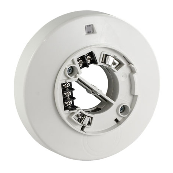
1. Description
This document provides instructions for mounting and wiring the Detector Bases
PAD100-IB, PAD100-RB and PAD100-SB. The following detectors are compatible
with Detector Bases PAD100-IB, PAD100-RB and PAD100-SB.
PAD100-PD:
Photoelectric Smoke Detector
PAD100-PHD:
Photoelectric Smoke / Heat Detector
PAD100-HD:
Heat Detector
PAD100-CD:
Carbon Monoxide Detector
2a. Field Wiring Diagram(s) for PAD100-IB
Typical field wiring diagrams for the Signaling Line Circuit (SLC) are shown in
FIGURE 1. The SLC supports NFPA wiring Class B, A and X.
First Base
To FACP
Loop (SLC)
ISOLATOR BASE
FACP
SLC
OUT
FIGURE 1: Wiring (Class B) Using PAD100-IB
FIGURE 1 is typical of NFPA Class B SLC (S+, S-) Wiring using the PAD100-IB base.
In Class A (FIGURE 2) arrangement two separate conducts would return from the
last detector base to a listed compatible Fire Alarm Control Panel (FACP). In
Class X, it is required to use PAD100-IB (Addressable Isolator Bases (FIGURE 3).
ISOLATOR BASE
FACP
SLC
IB
OUT
SLC
IB
IN
THE IB NEXT TO A FACP SHALL BE INSTALLED
WITHIN 20 FEET FROM THE TERMINAL OF THE FACP
FIGURE 2: Wiring (Class A) Using PAD100-IB
ISOLATOR BASE
FACP
SLC
OUT
SLC
IN
THE IB NEXT TO A FACP SHALL BE INSTALLED
WITHIN 20 FEET FROM THE TERMINAL OF THE FACP
FIGURE 3: Wiring (Class X) Using PAD100-IB
Installation Manual
Detector Bases:
PAD100-IB, PAD100-RB & PAD100-SB
Photoelectric Smoke Detector
Photoelectric Smoke / Heat Detector Combination (ANSI/UL 268 and ANSI/UL 521 Listed)
Heat Detector
Carbon Monoxide Detector
Last Base
ADDRESSABLE BASE / MODULE
IB
THE AREA TO BE ISOLATED BY
DETECTING THE SHORT CIRCUIT
IB
SHORT CIRCUIT
IB
IB
THE AREA TO BE ISOLATED BY
DETECTING THE SHORT CIRCUIT
IB
SHORT CIRCUIT
IB
IB
THE AREA TO BE ISOLATED BY
DETECTING THE SHORT CIRCUIT
IB
IB
SHORT CIRCUIT
(ANSI/UL 268 Listed)
(ANSI/UL 521 Listed)
(ANSI/UL 2075 Listed)
2b. Field Wiring Diagram(s) for PAD100-RB
Typical field wiring diagrams for the Signaling Line Circuit (SLC) are shown in
FIGURE 4. The SLC supports NFPA wiring Class B, A and X.
Normally
First Base
Open
Accessory
Alarm
Closed
Contacts
Normally
Closed
To FACP
Loop (SLC)
FIGURE 4: Wiring (Class B) Using PAD100-RB
FIGURE 4 is typical of NFPA Class B SLC (S+, S-) Wiring using the PAD100-RB base.
In Class A arrangement two separate conductors return from the last
detector base to a listed compatible Fire Alarm Control Panel (FACP). In Class
X, it is required to use PAD100-IB (Addressable Isolator Bases). The typical field
diagram is in Field Wiring Diagram(s) for PAD100-IB section of this manual.
2c. Field Wiring Diagram(s) for PAD100-SB
Typical field wiring diagrams for the Signaling Line Circuit (SLC) are shown in
FIGURE 5. The SLC supports NFPA wiring Class B, A and X.
24+
24-
To FACP
Loop (SLC)
FIGURE 5: Wiring (Class B) Using PAD100-SB
FIGURE 5 is typical of NFPA Class B SLC (S+, S-) Wiring using the PAD100-SB base.
In Class A arrangement two separate conductors would return from the last
detector base to a listed compatible Fire Alarm Control Panel (FACP). In Class
X, it is required to use PAD100-IB (Addressable Isolator Bases). The typical field
diagram is in Field Wiring Diagram(s) for PAD100-IB section of this manual.
3. Wiring Instruction
To ensure proper installation of the detector head to the base, wires shall be
dressed properly at the time of installation
When using PAD100 Bases, observe the correct polarity of SLC wiring.
NOTICE:
THE WIRING TO BE USED SHALL BE IN ACCORDANCE WITH THE
PROVISIONS OF ARTICLE 300.3(B) OF THE NATIONAL ELECTRICAL CODE,
NFPA 70, AS WELL AS ARTICLE 210.
THIS EQUIPMENT SHOULD BE INSTALLED IN ACCORDANCE WITH THE
NATIONAL FIRE PROTECTION ASSOCIATION STANDARD 72.
CAUTION! Break wire runs to provide supervision for connections made to each
wire pair.
Detector Base Mounting
PAD100-IB, PAD100-RB and PAD100-SB should be mounted directly on the
electrical box. The PAD100-IB, PAD100-RB and PAD100-SB mounting holes are
configured for a single gang, 4" octagon or 4" square box. Use a box for each
base and run the power circuit to all base locations.
Last Base
First Base
Last Base
Advertisement

Subscribe to Our Youtube Channel
Related Manuals for Potter PAD100-RB


Summary of Contents for Potter PAD100-RB
- Page 1 Last Base FIGURE 4: Wiring (Class B) Using PAD100-RB FIGURE 4 is typical of NFPA Class B SLC (S+, S-) Wiring using the PAD100-RB base. In Class A arrangement two separate conductors return from the last detector base to a listed compatible Fire Alarm Control Panel (FACP). In Class X, it is required to use PAD100-IB (Addressable Isolator Bases).
-
Page 2: Maintenance
OPERATION OF DIRTY VALUE READ / PRINT, ALARM SIMULATION AND WALK detector head. TEST. NOTICE: THE PAD100-IB, PAD100-RB AND PAD100-SB OBTAINS THE ADDRESS FROM Operational Testing THE DETECTOR HEAD. When PAD100-PD, PAD100-PHD, PAD100-HD and PAD100-CD are under normal THE DETECTORS AND THE PAD100 MODULES MUST HAVE INDIVIDUAL conditions in standby mode, the alarm indicator LEDs will pulse approximately ADDRESS(ES). -
Page 3: Locking Feature
4 inch detector base. See manual number: 550-0622-000 PAD100-4DB PAD100-IB 6 inch detector base with short circuit isolator PAD100-RB 6 inch detector base with relay module PAD100-SB 6 inch detector base with sounder module FIGURE 9: Replace Optic Cage into Optic Cage Base 8. -
Page 4: Limited Warranty
If the detector does not work properly, do not try and fix it yourself. This has been evaluated by a nationally recognized testing laboratory and found will void your warranty. For technical assistance, contact Potter Electric suitable for that purpose. - Page 5 10c. Specifications / Ratings for Use with Detector Bases: PAD100-RB Item PAD100-RB Working Voltage Range for SLC 24 VDC Standby / Alarm Current for SLC (*) 200 µA Auxiliary Contact Rating 2 A @ 30 VDC, 0.5 A @ 125 VAC...
- Page 6 These materials have been prepared by Potter Electrical Signal Company, LLC (“Potter”) for informational purposes only, are necessarily summary, and are not purported to serve as legal advice and should not be used as such. Potter makes no representations and...
Need help?
Do you have a question about the PAD100-RB and is the answer not in the manual?
Questions and answers