Table of Contents
Advertisement
Quick Links
EVD-2
ELECTRONIC VIBRATION DETECTOR
SYSTEM
INSTALLATION, OPERATION AND
INSTRUCTION MANUAL
EVD-R
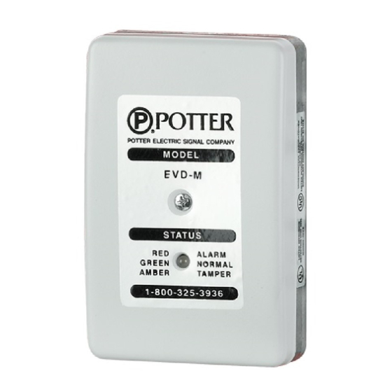
EVD-M
REMOTE PICKUP
CONTROLLER
RTA
(OPTIONAL)
POTTER ELECTRIC SIGNAL COMPANY
2081 CRAIG ROAD • P.O. BOX 28480 • ST. LOUIS, MO 63146-4161
(800) 325-3936 • (314) 878-4321 • FAX: (314) 878-7264
www.pottersignal.com
Manual #5401042 • Rev L • 5/03
ALL SPECIFICATIONS SUBJECT TO REVISION
Advertisement
Table of Contents

Subscribe to Our Youtube Channel
Related Manuals for Potter EVD-2


Summary of Contents for Potter EVD-2
- Page 1 EVD-R EVD-M REMOTE PICKUP CONTROLLER (OPTIONAL) POTTER ELECTRIC SIGNAL COMPANY 2081 CRAIG ROAD • P.O. BOX 28480 • ST. LOUIS, MO 63146-4161 (800) 325-3936 • (314) 878-4321 • FAX: (314) 878-7264 www.pottersignal.com Manual #5401042 • Rev L • 5/03 ALL SPECIFICATIONS SUBJECT TO REVISION...
- Page 2 The essential purpose of any sale or contract for sale of any of the products listed in the POTTER catalog or price list is the furnishing of that product. It is expressly understood that in furnishing said product, POTTER does not agree to insure the Purchaser against any losses the Purchaser may incur, even if resulting from the malfunction of said product.
-
Page 3: Table Of Contents
EVD-2 • 5401042 • REV L • 03/05 Contents GENERAL INFORMATION ....................5 FEATURES ..........................5 SPECIFICATIONS ........................ 5 ORDERING INFORMATION ....................5 EVD-M CONTROLLER ......................6 ACCUMULATOR FUNCTION ....................6 EVD-M CONTROLLER DETAILS ..................7 EVD-M TERMINAL CONNECTIONS ................... 7 EVD-R REMOTE PICKUP .................... - Page 4 EVD-2 • 5401042 • REV L • 03/05...
-
Page 5: General Information
The System must be used with an appropriate UL listed control unit. The standard EVD-2 system consists of a model EVD-M controller and a model EVD-R remote pickup. FEATURES •... -
Page 6: Evd-M Controller
When the number of valid signals matches the setting on the rotary switch, the EVD-M signals an alarm. This feature can be useful for installing an EVD-2 system where some noise is normal. The accumulator is only active when the rotary switch setting is NOT zero. -
Page 7: Evd-M Controller Details
EVD-2 • 5401042 • REV L • 03/05 Figure 1. EVD-M CONTROLLER DETAILS EVD-M TERMINAL CONNECTIONS TERMINAL TERMINAL DESCRIPTION NAME Power Supply Connection, +12 VDC, nominal (See note 1) Power Supply Connection, 0 VDC (See note 1) SPARE Spare Terminal Block Position... -
Page 8: Evd-R Remote Pickup
EVD-2 • 5401042 • REV L • 03/05 EVD-R REMOTE PICKUP The EVD-R remote pickup detects attack vibrations with the same vibration sensing components as the internal pickup on the EVD-M controller. The EVD-R amplifies and transmits these vibrations to the EVD-M controller. -
Page 9: Evd-R Remote Pickup Details
EVD-2 • 5401042 • REV L • 03/05 Figure 3. EVD-R REMOTE PICKUP DETAILS EVD-R TERMINAL CONNECTIONS TERMINAL TERMINAL DESCRIPTION NAME SHIELD Input Shield Connection from OUT SHIELD of Previous Pickup or End of Line Resistor (See note 1) SIGNAL... -
Page 10: Recommended Wiring Evd-2 System
EVD-2 • 5401042 • REV L • 03/05 Figure 4. RECOMMENDED WIRING EVD-2 SYSTEM (Shown with 2 additional EVD-R remote pickups) EVD-R EVD-M EVD-R EVD-R... -
Page 11: Recommended Wiring
EVD-2 • 5401042 • REV L • 03/05 RECOMMENDED WIRING Figure 4 shows the recommended wiring for an EVD-2 system with two additional EVD-R remote pickups. (All wiring should be as specified in Table 1 or with UL listed equivalents.) Cable clamp knockout locations are shaded. -
Page 12: Recommended Control Panel Wiring And Rta Connections
Verify proper installation of the end of line resistors. Refer to Figures 2b and 4 for systems with remote pickups. Wire control unit connections and apply 12 VDC to the EVD-2 system. Refer to Figure 5a. See Figure 5b & 5c for 4 or 6 wire installation wiring. -
Page 13: Evd Wiring With Safe Detector Zone And 24 Hour Alarm Zone
EVD-2 • 5401042 • REV L • 03/05 RECOMMENDED CONTROL PANEL WIRING WITH SAFE DETECTOR ZONE AND 24 HOUR ALARM ZONE (High security B cable and connections to 24 hr zone as shown are required for UL safe compatible installations) -
Page 14: Evd Wiring With Safe Detector Zone Only
EVD-2 • 5401042 • REV L • 03/05 RECOMMENDED CONTROL PANEL WIRING WITH SAFE DETECTOR ZONE ONLY (4 Conductor Shielded Cable Required) Figure 5c... -
Page 15: Sensitivity Adjustments
EVD-2 • 5401042 • REV L • 03/05 SENSITIVITY ADJUSTMENTS Adjust the EVD-M’s internal pickup sensitivity control, RV1, to 1/2 scale (12 o’clock position). Refer to Figure 1 for adjustment location. If remote pickups are installed, adjust the EVD-M’s remote pickup network sensitivity control, RV2, to the minimum setting listed in Table 2. -
Page 16: Testing
EVD-2 • 5401042 • REV L • 03/05 TESTING Applying a magnet to the side of the EVD-M controller, (see Figure 1), actuates a magnetic switch and generates a test signal. Similarly, applying a magnet to the side of an EVD-R remote pickup , (see Figure 3), actuates a magnetic switch and causes the EVD-R to transmit a test signal to the EVD-M controller. -
Page 17: Recommended Detector Locations
EVD-2 • 5401042 • REV L • 03/05 RECOMMENDED DETECTOR LOCATIONS Single Detector Applications All safe applications must have at least an EVD-M or an EVD-R on the body of the Figure 6. safe. When only one detector is required... -
Page 18: Determining The Number Of Detectors For A Safe Application
(if safe has double doors). In some single detector applications, the EVD-2 system may be used to protect multiple safes via a combination of an EVD-M and multiple EVD-R remote pickups. For applications with a larger distance than that shown in Table 5, consult Potter’s technical support for assistance. -
Page 19: Determining The Maximum Linear Distance On A Safe
In those cases, contact Potter’s technical support for assistance. Table 6 lists some common safe dimensions and their maximum linear distances when detectors are installed in recommended locations. -
Page 20: Typical Ul Complete Safe Installations
EVD-2 • 5401042 • REV L • 03/05 TYPICAL UL COMPLETE SAFE INSTALLATIONS 1. Install in accordance with Underwriter Laboratories’ standard UL 681. 2. Install EVD-M and EVD-R detectors in recommended locations at recommended spacings. 3. Install UL listed, high security contacts on the exterior of the safe or UL listed, ordinary use contacts on the inside of the safe. -
Page 21: Recommended Maximum Evd-M/Evd-R Spacing
EVD-2 • 5401042 • REV L • 03/05 Table 7. RECOMMENDED MAXIMUM EVD-M/EVD-R SPACING FOR WALL PROTECTION i t i i n i ' 0 . ' 3 . ' 9 . ' 5 . ' 6 . f l a ' 0 . -
Page 22: Evd-M Or Evd-R Mounting Template
EVD-2 • 5401042 • REV L • 03/05 Figure 11. EVD-M OR EVD-R MOUNTING TEMPLATE ALL DIMENSIONS IN INCHES...
Need help?
Do you have a question about the EVD-2 and is the answer not in the manual?
Questions and answers