Advertisement
Quick Links
PAD100-PD
PAD100-PHD
PAD100-HD
PAD100-CD
1. Description
This document provides instructions for mounting and wiring the detector bases
PAD100-LFSB and PAD100-SPKB. The following detectors are compatible with
detector bases PAD100-LFSB and PAD100-SPKB.
PAD100-PD:
Photoelectric Smoke Detector
PAD100-PHD:
Photoelectric Smoke / Heat Detector
PAD100-HD:
Heat Detector
PAD100-CD:
Carbon Monoxide Detector
2a. Field Wiring Diagram for PAD100-LFSB
Typical field wiring diagrams for the Signaling Line Circuit (SLC) (FIGURE 1). The
SLC supports NFPA wiring Class B, A and X. (FIGURE 1) Typical of NFPA Class B SLC
(S+, S-) Wiring using the PAD100-LFSB base. In Class A arrangement two separate
conductors would return from the last detector base to a listed compatible Fire
Alarm Control Panel (FACP).
24+
24-
To FACP
Loop (SLC)
FIGURE 1: Wiring (Class B) Using PAD100-LFSB
Class X Wiring (FIGURE 2), requires use of PAD100-IM (Addressable Isolator
Module). The typical field diagram is in Field Wiring Diagram(s) for PAD100-IM.
The PAD100-IM manual can be obtained at www.pottersignal.com
ISOLATOR MODULE
FACP
SLC
IM
OUT
SLC
IM
IN
THE IM NEXT TO A FACP SHALL BE INSTALLED
WITHIN 20 FEET FROM THE TERMINAL OF THE FACP
FIGURE 2: Wiring (Class X) Using PAD100-LFSB and PAD100-IM
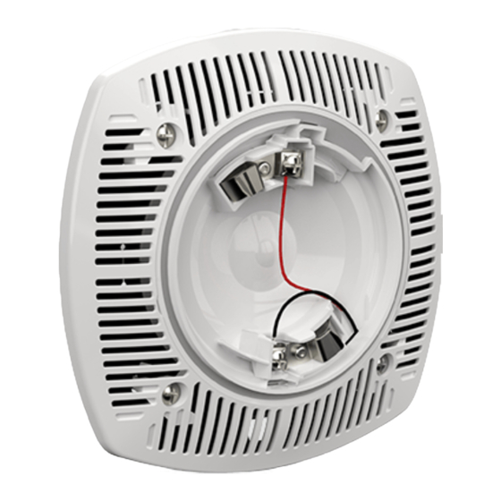
FIGURE 3: PAD100-LFSB Wiring
2b. Field Wiring Diagram for PAD100-SPKB
Typical field wiring diagrams for the Signaling Line Circuit (SLC) (FIGURE 4). The
SLC supports NFPA wiring Class B, A and X. The PAD100-SPKB offer a choice of
field selectable power taps: 1/8, 1/4, 1/2, 1, 2 and 4 watts (FIGURE 5) for use
with either 25 VRMs or 70.7 VRMs audio amplifiers. The frequency range of the
PAD100-SPKB is 400-4000 Hz. The PAD100-SPKB is suitable for line supervision.
The PAD100-SPKB includes DC blocking capacitor which allows for supervision
voltage of either polarity.
Installation Manual
Detector Bases:
PAD100-LFSB, PAD100-SPKB
Photoelectric Smoke Detector
Photoelectric Smoke / Heat Detector Combination (ANSI/UL 268 and ANSI/UL 521 Listed)
Heat Detector
Carbon Monoxide Detector
First Base
Last Base
IM
THE AREA TO BE ISOLATED BY
DETECTING THE SHORT CIRCUIT
IM
SHORT CIRCUIT
PWR
SLC
(ANSI/UL 268 Listed)
(ANSI/UL 521 Listed)
(ANSI/UL 2075 Listed)
FIGURE 4: PAD100-SPKB Wiring Diagram
Adjust power taps using
needle nose pliers.
FIGURE 5: PAD100-SPKB Wiring and Power Tap
3. Wiring Instruction
To ensure proper installation of the detector head to the base, wires shall be
dressed properly at the time of installation
When using PAD100-SPKB / PAD100-LFSB base, observe the correct polarity of
SLC wiring.
NOTICE:
THE WIRING TO BE USED SHALL BE IN ACCORDANCE WITH THE
PROVISIONS OF ARTICLE 300.3(B) OF THE NATIONAL ELECTRICAL CODE,
NFPA 70, AS WELL AS ARTICLE 210.
THIS EQUIPMENT SHOULD BE INSTALLED IN ACCORDANCE WITH THE
NATIONAL FIRE PROTECTION ASSOCIATION STANDARD 72.
DO NOT USE LOOPED WIRE UNDER TERMINALS. BREAK WIRE RUN TO
PROVIDE SUPERVISION OF CONNECTION.
CAUTION!
Break wire runs to provide supervision for connections made to each wire pair.
When installing, route field wiring away from sharp projections, corners and
internal components.
Detector Base Mounting
PAD100-LFSB / PAD100-SPKB should be mounted directly on the electrical box
(FIGURE 6a) or to the LFSBBB-W back box (FIGURE 6b). The PAD100-LFSB /
PAD100-SPKB mounting holes are configured for a 4" x 2-1/8" deep square box.
Use a box for each base and run the power circuit to all base locations.
Use 12 to 18 AWG conductors to connect to terminals of bases. It is
recommended that the SLC conductors be color-coded to avoid wiring errors and
assist in system troubleshooting. Improper SLC connections may prevent the
system from operating normally. Disconnect power to the SLC until the detectors
are installed.
1. Wire the detector bases according to Field Wiring Diagrams.
2. Use the dip switches (SECTION 11) to set address(es) (1 - 127) for each
detector head.
NOTICE:
THE PAD100-LFSB /PAD100-SPKB OBTAINS THE ADDRESS FROM THE
DETECTOR HEAD.
THE DETECTORS AND THE PAD100 MODULES MUST HAVE INDIVIDUAL
ADDRESS(ES).
3. To install the detector head onto the base, match the detector heads to the
base using the alignment feature and twist clockwise until the detector heads
snap into place (FIGURE 6a).
SPK
SLC
Manual Number: 550-0706
Advertisement

Related Manuals for Potter PAD100-LFSB


Summary of Contents for Potter PAD100-LFSB
- Page 1 SLC supports NFPA wiring Class B, A and X. (FIGURE 1) Typical of NFPA Class B SLC FIGURE 4: PAD100-SPKB Wiring Diagram (S+, S-) Wiring using the PAD100-LFSB base. In Class A arrangement two separate conductors would return from the last detector base to a listed compatible Fire Alarm Control Panel (FACP).
-
Page 2: Maintenance
Alarm Set-Point Rate of Rise Spacing Fixed Temperature Spacing Mount the PAD100-LFSB / to 174 Maximum 60 ft. Maximum 60 ft. Alignment PAD100-SPKB base to the to 79 Features electrical box using the provided mounting to 185 Maximum 15 ft. -
Page 3: Locking Feature
See manual number: 550-0671-000 6 inch detector base with sounder module. PAD100-SB See manual number: 550-0671-000 PAD100-LFSB 6 inch detector base with low frequency sounder module FIGURE 9: Replace Optic Cage into Optic Cage Base PAD100-SPKB 6 inch detector base with speaker module... - Page 4 The standby current is the current that the device consumes when the device is in a non-activated condition and where no communication current is transmitted to the FACP. ** Reference spacing requirements in Section 4. 10b. Specifications / Ratings for Use with Detector Bases: PAD100-LFSB Item...
-
Page 5: System Considerations
10c. Specifications / Ratings for Use with Detector Bases: PAD100-SPKB Item PAD100-SPKB Working Voltage Range for SLC 24 VDC Standby / Alarm Current for SLC (*) 150 µA Active Current (Including Indicator) 3.8 mA Working Voltage for SPK 25 Volts, 70.7 Volts Power Tap Selection for SPK 1/8 Watt , 1/4 Watt, 1/2 Watt, 1 Watt, 2 Watt, 4 Watt Applicable SLC Wiring Style... - Page 6 These materials have been prepared by Potter Electric Signal Company, LLC (“Potter”) for informational purposes only, are necessarily summary, and are not purported to serve as legal advice and should not be used as such. Potter makes no representations and...
Need help?
Do you have a question about the PAD100-LFSB and is the answer not in the manual?
Questions and answers