Table of Contents
Advertisement
Available languages
Available languages
Quick Links
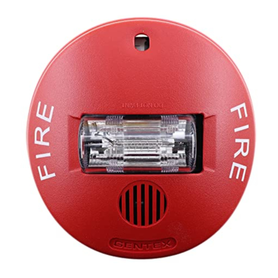
SELECTABLE CANDELA CEILING STROBE AND HORN/STROBE
ADDITIONAL CAN/ULC LISTED PRODUCT INFORMATION IS FOUND ON PAGE 4
I. INTRODUCTION
The Potter Electric Model CS-24, CHS-24, CCS-24A, CCHS-24A, CCS-24B, CCHS-24B, CCS-24G, CCHS-24G, CCS-24R, CCHS-24R strobe and horn/strobe, is a high quality visible or
audible/visible signaling appliance intended for ceiling applications. The high intensity strobe utilizes a Xenon flash tube that generates a high-intensity flash visible from all angles. This appliance
is intended to provide a visible or audible/visible, depending on the model, notification signal for the purpose of life safety and property protection. This appliance is ideal for any occupancy that
requires notification appliances per the applicable building or fire code or wherever dependable alarms are required. The CS-24 and CHS-24 strobe is listed in compliance with ANSI/UL 1971,
Signaling Appliances for the Hearing Impaired. The CCS-24A, CCHS-24A, CCS-24B, CCHS-24B, CCS-24G, CCHS-24G, CCS-24R, CCHS-24R strobe is listed in compliance with ANSI/UL 1638,
Visual Signaling Appliances - Private Mode Emergency and General Signaling.
II. LOCATION
This appliance is intended for use in Fire Alarm Systems and is to be installed in accordance with this manual, the recommendation of the local authorities having jurisdiction, and other NFPA
documents that provide standards on notification appliances for protective signaling systems. The CS-24, CHS-24, CCS-24A, CCHS-24A, CCS-24B, CCHS-24B, CCS-24G, CCHS-24G, CCS-24R,
CCHS-24R is intended for indoor installations only. This appliance is not listed for outdoor or drip proof applications. Spacing for the CS-24 and CHS-24 shall be in accordance with Table A. If a
room configuration is not square, the room size that will entirely encompass the room or subdivide the room into multiple squares shall be used.
III. MOUNTING, ROUGH-IN BOX AND RUN WIRING
This unit is designed for mounting to most single gang boxes, 4" square outlet boxes, 2-gang masonry boxes or non-metallic 2-gang switch boxes. Conduit entrance to boxes should be selected to
insure sufficient wiring clearance.
1. Run a minimum 18 gauge insulated 2 or more conductor cable.
2. Mount a box for each remote signaling appliance. Screw bracket onto box. Insert signal into bracket and slide to the right firmly into the terminal block receptacle. Insert mounting screw as
shown and tighten. Cover assembly with the plastic housing.
NOTICE: WIRING SHOULD BE CONNECTED TO MOUNTING BRACKET PRIOR TO MOUNTING SIGNAL. INCOMING POSITIVE POWER LEAD MUST BE BROKEN AND EACH LEAD IS TO
BE INSERTED INTO EACH OF THE TOP TWO TERMINALS. IF TWO POWER RUNS ARE MADE TO THE SIGNAL, ONE FOR THE STROBE AND ONE FOR THE HORN, ONLY ONE OF THE
RUNS MUST HAVE ITS POSITIVE LEAD BROKEN AND PLACED UNDER THE TWO SEPARATE TOP TERMINALS. A BARRIER IS PROVIDED TO PREVENT BOTH LEADS FROM BEING
PLACED UNDER THE SAME TERMINAL
Table A
6.10 x 6.10
9.14 x 9.14
13.4 x 13.4
15.2 x 15.2
Regulated 24VDC Max.
Candela
Operating Current (mA)
15
120
30
120
75
200
95
220
115
290
150
321
CS-24 & CHS-24 SERIES
ANSI/UL & CAN/ULC COMPLIANT
CCS-24A, CCHS-24A, CCS-24B, CCHS-24B,
CCS-24G, CCHS-24G CCS-24R, & CCHS-24R SERIES
ANSI/UL & CAN/ULC COMPLIANT
.
CS-24 AND CHS-24 PRODUCT INFORMATION
Room Spacing for Ceiling-Mounted Visible Appliances per NFPA 72, 2013 Edition
Maximum Room Size
Meters
Feet
10 Foot Ceiling
20 x 20
30 x 30
44 x 44
50 x 50
CLEAR Lens Strobe Current Ratings
Use with CS-24 & CHS-24 Products
Regulated 24VFWR Max.
Operating Current (mA)
190
191
277
298
418
427
firealarmresources.com
Minimum Required Light Output (Effective Intensity, Cd; One Light)
Maximum Ceiling Height
20 Foot Ceiling
15
30
30
45
75
75
NA
NA
CAUTION: Strobe light must be installed within 16
feet of the pillow when used in a sleeping area.
NOTICE: THE VISUAL SIGNAL MUST BE IN THE DIRECT VIEWING AREA OF THE OCCUPANT IN ORDER
TO BE SEEN.
Strobe light can not be seen when objects such as doors, furniture or walls block
strobe light.
NOTICE: VISUAL SIGNALS FOR THE HEARING IMPAIRED ARE ONLY ONE METHOD OF ALERTING THE
HEARING IMPAIRED. VISUAL SIGNALS MAY NOT BE THE PREFERRED METHOD FOR NOTIFYING ALL
HEARING IMPAIRED INDIVIDUALS.
NOTICE: THE STROBE LIGHT MUST BE SEEN BY THE SLEEPING PERSON. IF THE PERSON HAS HEAD
TURNED OR OTHERWISE UNABLE TO BE ALERTED BY VISUAL, THE STROBE WILL NOT BE EFFECTIVE.
24VDC Nominal
Operating Current (mA)
97
97
143
148
201
205
30 Foot Ceiling
55
75
NA
95
NOTICE: DC VOLTAGE RANGE LIMITS: 16-33V. FWR VOLTAGE
RANGE LIMITS: 16-33V. THIS PRODUCT WAS ONLY TESTED TO
THE STATED VOLTAGE RANGE(S); DO NOT APPLY 80% AND
110% OF THIS RANGE FOR SYSTEM OPERATION.
NA = Not allowable
550-0594
Page 1
Advertisement
Table of Contents

Subscribe to Our Youtube Channel
Related Manuals for Potter CS-24 Series


Summary of Contents for Potter CS-24 Series
- Page 1 I. INTRODUCTION The Potter Electric Model CS-24, CHS-24, CCS-24A, CCHS-24A, CCS-24B, CCHS-24B, CCS-24G, CCHS-24G, CCS-24R, CCHS-24R strobe and horn/strobe, is a high quality visible or audible/visible signaling appliance intended for ceiling applications. The high intensity strobe utilizes a Xenon flash tube that generates a high-intensity flash visible from all angles. This appliance is intended to provide a visible or audible/visible, depending on the model, notification signal for the purpose of life safety and property protection.
- Page 2 ON position on the CHS-24, CCHS-24A, CCHS-24B, CCHS-24G, CCHS-24R). Mute the horn only when the temporal horn option has been selected. Use the Potter Electric AVSM synchronization protocol to provide synchronization and mute the horn, if available. Wiring for synchronized parallel (unison) horn/strobe operation.
- Page 3 5. Return to: Potter Electric Signaling Company, LLC 1609 Park 370, Hazelwood, MO 63042. Prior to returning, call the Potter Electric field service department at 1-800-325-3936 to obtain a RMA number.
- Page 4 LIMITED WARRANTY For a period of 60 months from the date of manufacture (or as long as required by applicable law), Potter Electrical Signal Company, LLC warrants to you the original purchaser that your appliance will be free from defects in workmanship and materials under normal use and service.
- Page 5 I. INTRODUCTION Les modèles CS-24, CHS-24, CCS-24A, CCHS-24A, CCS-24B, CCHS-24B, CCS-24G, CCHS-24G, CCS-24R, CCHS-24R de stroboscope et avertisseur stroboscope de Potter Electric sont des appareils de signalisation visuelle ou sonore et visuelle de grande qualité conçus pour être installés au plafond. Le stroboscope à haute intensité fait appel à un tube à éclair au xénon qui émet un puissant flash à...
- Page 6 Couper l’avertisseur uniquement lorsque le mode temporel a été sélectionné. CONDUCTIVITE w Utiliser le AVSM protocole de synchronisation Potter Electric, s’il est disponible, pour assurer la synchronisation et couper l’avertisseur. 18 AWG Câblage pour la synchronisation parallèle (mode unisson) du stroboscope et de l’avertisseur.
- Page 7 5. Retourner à : Potter Electric Signaling Company, LLC 1609 Park 370, Hazelwood, MO 63042. Avant de retourner l’appareil, appeler Potter Electric au 1 800 325-3936 pour obtenir un numéro d’autorisation de retour (RMA) du Service à...
- Page 8 à la mise en application de ces lois et règlements en fonction des situations particulières. Les activités de chaque personne peuvent modifier les obligations pertinentes en vertu des lois ou des règlements en vigueur. Par conséquent, ces renseignements ne doivent être utilisés qu’à des fins infor- mationnelles et ne doivent pas servir à remplace un avis juridique professionnel. Potter n’assumera aucune responsabilité quant aux mesures ou activités qui pourraient être, ou ne pas être, prises ou effectuées à la suite de ces renseignements.
Need help?
Do you have a question about the CS-24 Series and is the answer not in the manual?
Questions and answers