Table of Contents
Advertisement
Quick Links
Installation Manual: PAD100-DUCT Analog Addressable Duct Detector
NOTICE TO THE INSTALLER
This manual provides an overview and the installation instructions for the PAD100-DUCT module. This module is only compatible
with addressable fire systems that utilize the PAD Addressable Protocol.
All terminals are power limited and should be wired in accordance with the requirements of NFPA 70 (NEC) and NFPA 72 (National
Fire Alarm Code). Failure to follow the wiring diagrams in the following pages will cause the system to not operate as intended. For
further information, refer to the control panel installation instructions.
The module shall only be installed with listed control panels. Refer to the control panel installation manual for proper system
operation.
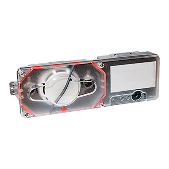
1. Description
The PAD100-DUCT duct smoke detector provides early detection of smoke and products of combustion present in the air moving
through HVAC ducts in commercial, industrial and residential applications. The PAD100-DUCT is designed and built to meet all
local requirements, as well as the NFPA regulations regarding duct smoke detectors.
Air sampling is accomplished by two tubes which protrude into the duct. An exhaust tube of one standard length (7") is supplied
in the installation kit with the smoke duct unit. Once the duct width has been determined, the air intake sampling tubes must be
ordered. Sampling tubes are supplied in three standard lengths: 2.5 ft., 5 ft., and 10 ft. and cut to size to fit the duct. Mounting
the duct smoke unit is accomplished by the use of a template and 2 sheet metal screws, which are provided. Mounting can be
achieved without the removal of the clear cover which is secured by 4 capture screws.
2. Setting the Address
All PAD protocol detectors and modules require an address prior to connection to the panel's SLC loop. Each PAD device's
address (i.e., detector and/or module) is set by changing the dip switches located on the device. PAD device addresses are
comprised of a seven (7) position dip switch used to program each device with an address ranging from 1–127.
Figure 1. PAD Device Dip Switch Addresses Table (Addresses 1–127)
1
2
4
8 16 32 64
1
27
2
28
3
29
4
30
5
31
6
32
7
33
8
34
9
35
10
36
11
37
12
38
13
39
14
40
15
41
16
42
17
43
18
44
19
45
20
46
21
47
22
48
23
49
24
50
25
51
26
52
1
2
4
8 16 32 64
Note: Each "gray" box indicates that the dip switch is "On," and each "white" box indicates "Off."
Potter Electric Signal Company, LLC
1
2
4
8 16 32 64
1
2
53
54
55
56
57
58
59
60
61
62
63
64
65
66
67
68
69
70
71
72
73
74
75
76
77
1
2
1
2
4
8 16 32 64
•
St. Louis, MO
Document 5406322-A 05/16
firealarmresources.com
4
8 16 32 64
1
2
4
8 16 32 64
78
79
80
81
82
83
84
85
86
87
88
89
90
91
92
93
94
95
96
97
98
99
100
101
102
4
8 16 32 64
1
2
4
8 16 32 64
•
Phone: (800) 325-3936
1
2
4
8 16 32 64
103
104
105
106
107
108
109
110
111
112
113
114
115
116
117
118
119
120
121
122
123
124
125
126
127
1
2
4
8 16 32 64
•
www.pottersignal.com
PAGE 1 OF 4
Advertisement
Table of Contents

Subscribe to Our Youtube Channel
Related Manuals for Potter PAD100-DUCT


Summary of Contents for Potter PAD100-DUCT
- Page 1 1. Description The PAD100-DUCT duct smoke detector provides early detection of smoke and products of combustion present in the air moving through HVAC ducts in commercial, industrial and residential applications. The PAD100-DUCT is designed and built to meet all local requirements, as well as the NFPA regulations regarding duct smoke detectors.
- Page 2 Sampling Tube Part Numbers 2.5' = 1000274, 5' = 1000275, 10' = 1000276 4. Wiring Diagram The wiring diagram shown below illustrates how to wire a PAD100-DUCT duct detector. Figure 3. Example of Wiring a PAD100-DUCT Duct Detector +SLC TO NEXT MODULE...
- Page 3 LOCATION PREREQUISITES: This guideline contains general information on the PAD100-DUCT duct smoke detector installation, but does not preclude the NFPA and/or ICC documents listed. Potter Electric Signal Company assumes no responsibility for improperly installed duct detectors. To determine the correct installation position for a PAD100-DUCT duct smoke detector, the following factors must be considered.
- Page 4 Specifications subject to change without prior notification. For Technical Assistance contact Potter Electric Signal Company at 866-956-1211. Actual performance is based on proper application of the product by a qualified professional.
Need help?
Do you have a question about the PAD100-DUCT and is the answer not in the manual?
Questions and answers