Advertisement
Quick Links
Advertisement

Related Manuals for Poynting EPOYNT-4


Summary of Contents for Poynting EPOYNT-4
- Page 1 Revision 2.0...
- Page 2 Revision 2.0...
- Page 3 Packing Check List Introduction Setting up the CPE CPE Mounting Configurations CPE Mounting Precautions Cable Routing Safety Basic Troubleshooting Revision 2.0...
- Page 4 Item Description Quantity EPOYNT-4 CPE Only Wall Knock-in Screws 3mm Allen Key 5mm Allen Key Pipe Clamp Surface Mount Gasket M6 x 90mm Stainless Steel U-Bolts PCB Mounting Screws 4 Cable Ties M6 Nyloc and Standard Stainless Steel Nuts M6 Stainless Steel Flat Washers Revision 2.0...
- Page 5 EPoynt-4 CPE Wall Knock-in Screw Allen Key Pipe Clamp Surface Mount Gasket Revision 2.0...
- Page 6 PCB Mounting Screws U-Bolt Cable Tie M6 Nut and Washer Cable Tie Revision 2.0...
- Page 7 6mm Masonry Drill Bit Impact Drilling Machine Hammer Safety Goggles Screwdriver – Cross Slot/Philips Revision 2.0...
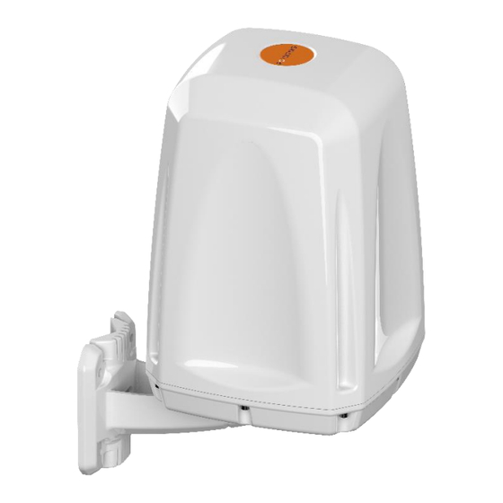
- Page 8 This User Guide provide information on the installation instructions of the EPoynt-4 CPE. Install your router into the CPE Step 1 • Carefully unscrew the bracket cap screws using the provided 5mm allen key. Revision 2.0...
- Page 9 • To access the router mounting plate, carefully unscrew the cap screws at the bottom of the CPE using the provided 3mm allen key • Remove the mounting plate from the CPE base by carefully unscrewing it using a Philips screwdriver. •...
- Page 10 • Connect the CPE’s antenna cables to the respective connectors on the router (LTE and/or Wi-Fi) using a suitable fly lead (sold separately). Unused antenna cables should be neatly wound and attached to the antenna plate appropriately. • Route an Ethernet cable through the bracket and into the CPE’s base.
- Page 11 Note: If you are using a power supply to power your router, route your power cable through the bracket and into the central hole in the middle of the CPE base. • Connect the Ethernet cable from the CPE’s base to the router port labelled “PoE” or to any other router Ethernet port in case you will be using a power supply to power your router.
- Page 12 • Carefully place the CPE cover to close the CPE and screw the cap screws at the bottom of the base firmly. Do not over- tighten the screws, as this could strip the plastics. • Carefully screw the bracket back to the CPE using the provided 5mm allen screw.
- Page 13 Step 2 Power your CPE • Connect the other end of the Ethernet cable protruding from the CPE’s bracket to the port labelled “PoE” on the PoE adapter. • Connect another network cable to the port labelled “LAN” on the PoE adapter and connect the other end of the cable to a computer or to a WAN/LAN port of an access point or switch.
- Page 14 Note: Ensure that all RF/electrical connections made outdoors are adequately waterproofed. Waterproof connector boots are recommended. Wall mount with wall knock-in screws. • Select a suitable place for mounting the • Use a 6mm masonry drill bit to drill four holes into the wall.
- Page 15 Pole mount with supplied U-bolts or pipe clamps. • Select a suitable place for mounting the • Lay the CPE out at the installation site and assemble the CPE on the ground. • Place the pipe clamps or U-bolts through the bracket as shown below.
- Page 16 a) Surface mount with supplied surface mount gasket. • Select a suitable surface for mounting the CPE • Remove the CPE bracket by unscrewing the cap screws on the bracket using the provided 5mm allen key. • Use a 6mm masonry drill bit to drill four holes into the surface.
- Page 17 • Route the Ethernet cable from the gasket through the drilled central hole and then carefully screw the CPE onto the surface using appropriate M6 machine screws. b) Surface mount using optional bracket (BRKT- 038) and MISC 103 Kit - NOT provided. •...
- Page 18 • Place the CPE base followed by the second locking nut over BRKT-038 and tighten the CPE base firmly into place. Do not over-tighten the nuts, as this could crack the CPE base. • Route the Ethernet cable through the CPE base.
- Page 19 • Mount your CPE to a suitable horizontal rail. Note: The installer should ensure that the BRKT-38 cable entry hole is adequately waterproofed to maintain the CPE’s IP rating. Additionally, should the thread of the marine mount bracket protrude too far into the CPE, make use of the locking nuts to raise the CPE base on it.
- Page 20 • Avoid installing the antenna near a chimney, as the smoke and soot emitted by the chimney can obstruct the signal level achieved by the CPE’s antenna. • Install the CPE away from heat sources and flammable gases. • If the CPE is mounted on a pole, avoid wrapping the Ethernet cable around the pole.
- Page 21 • If you are installing the CPE for the first time or unsure about how to install your CPE, obtain the help of a professional installer. • Carefully survey the installation site before installation to locate secure handholds, dangerous conditions (such as powerlines and weak roofs) and the safest and most convenient placement for ladders if necessary.
- Page 22 • When drilling remember: 1. Use safety goggles when drilling the holes. 2. Avoid using bits that are dull, bent or damaged. 3. Be aware of where your fingers are in relation to the drill bit when using the drilling machine. 4.
- Page 23 1. The CPE does not power ON. • Make sure that the PoE adapter is fully plugged into the electrical socket and that the PoE power light is ON. • If the PoE 's power light does not turn ON, check the electrical outlet with another electrical device that you know works or try a different outlet.
- Page 24 Landmarks Ave 81677 München Suite 104, Mansfield, Samrand, 0157 Germany TX 76063 South Africa Tel: +49 89 2080 265 38 Tel: +1 817 533-8130 Tel: +27 12 657 0050 Mob.: +49 176 529 733 50 sales-us@poynting.tech info@poynting.tech sales-europe@poynting.tech Revision 2.0...
Need help?
Do you have a question about the EPOYNT-4 and is the answer not in the manual?
Questions and answers