Advertisement
Quick Links
www.poynting.tech
South Africa
Unit 4, N1 Industrial Park
Landmarks Ave
Samrand, 0157,
South Africa
Tel: +27 12 657 0050
info@poynting.tech
Making wireless happen
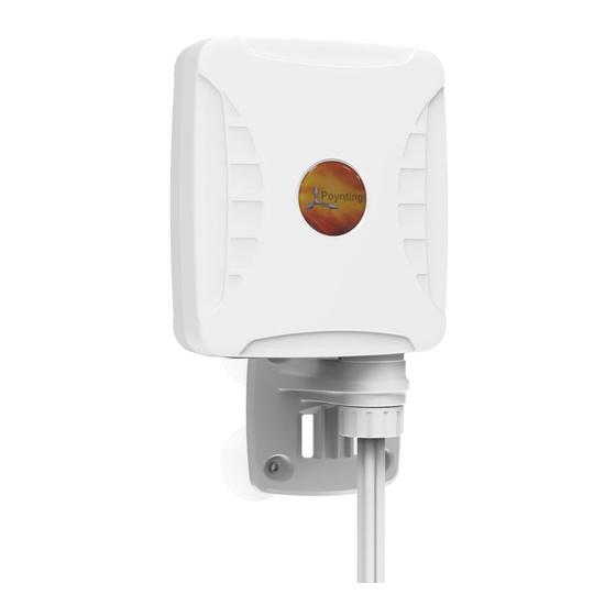
XPOL-1-5G
User Guide
Version: 3.0
Europe
Kronstadler Straße 4,
81677 München
Germany
Tel: +49 89 2080 265 38
Mob.: +49 176 529 733 50
sales-europe@poynting.tech
Advertisement

Related Manuals for Poynting XPOL-1-5G


Summary of Contents for Poynting XPOL-1-5G
- Page 1 Making wireless happen www.poynting.tech XPOL-1-5G User Guide South Africa Europe Unit 4, N1 Industrial Park Kronstadler Straße 4, Landmarks Ave 81677 München Samrand, 0157, Germany South Africa Tel: +49 89 2080 265 38 Tel: +27 12 657 0050 Mob.: +49 176 529 733 50 info@poynting.tech...
- Page 2 XPOL-1-5G_PCL...
- Page 3 Index Packing Check List Tools Required Introduction Antenna Mounting Precautions Cable Routing Safety Version: 3.0...
- Page 4 Packing Check List Item Description Quantity A-XPOL-1-5G Antenna Only Pipe clamp Suckers Sucker mounting pins Wall knock-in screws SMA grip extender XPOL-1-5G_PCL...
- Page 5 The appearance of each component Antenna Unit Pipe Clamp Suckers Sucker mounting pins Wall knock-in screws SMA grip extender Version: 3.0...
- Page 6 Tools Required Tools which may be required: 6mm Masonry drill bit Impact drilling machine Screw driver-Cross slot/Philips Hammer XPOL-1-5G_PCL...
-
Page 7: Mounting Configurations
Introduction XPOL-1-5G is a unique window, wall or pole mountable, high gain, CPE antenna. It can be mounted outdoors on a pole of up to 50mm in diameter, against a window or against a wall. Follow the instructions below for installation. - Page 8 Introduction 2. Window Mounting • Select a suitable mounting place for mounting the antenna. • Clean the selected area to remove the dirt. • Place each of the four suckers through the holes in the bracket. • Insert the sucker pins from the front of the bracket into the hole in the four suckers.
- Page 9 Introduction 3. Pole Mounting • Lay the antenna out at the installation site and assemble the antenna on the ground. • Place the pipe clamp through the bracket as shown below. • Place the cable clamp around the pole and tighten the screw on the cable clamp until the bracket is secured to the pole.
-
Page 10: Cable Routing
Antenna Mounting Precautions • Place the antenna at the highest point possible and ensure that there aren’t any surrounding obstructions to the antenna. • In order to avoid communication interference, ensure that the antenna is placed at least 0.5m away from other antennas and metal objects. •... - Page 11 Cable Routing 4x4 Cable Connection • Connect Cell 1(Main) cable to the respective Cell 1(Main) connector of the router. Similarly, connect Cell 2(Main) cable to the respective Cell 2 (Main) connector of the router. • Connect Cell 1 (Aux/Div) cable to the respective Cell 1 (Aux/Div) connector of the router.
- Page 12 2(Aux/Div) connector of the router. • In case of a 2-port LTE router, use one of the antenna diversity cable pairs. Use either Cell 1 (Main) & Cell 1 (Aux/Div) cables or Cell 2 (Main) & Cell 2 (Aux/Div) cables. Incase of two routers that have two LTE •...
- Page 13 5. Make sure that any loose-fitting jewellery or clothing is secured and tie back long hair as they can get caught in moving parts during installation. If the antenna assemble starts to fall, get away from it and let it fall to avoid harm to yourself.
Need help?
Do you have a question about the XPOL-1-5G and is the answer not in the manual?
Questions and answers