Table of Contents
Advertisement
Quick Links
Advertisement
Table of Contents

Related Manuals for Poynting Wavehunter


Summary of Contents for Poynting Wavehunter
- Page 1 Head Office Johannesburg A: Unit 4, N1 Industrial Park, Landmarks Ave, Samrand, 0157, South Africa P: PO Box 76579, Wendywood, 2144, South Africa Poynting Group (Pty) Ltd T: +27 12 657 0050 | E: info@poynting.tech Registration Number: 2014/239013/07 www.poynting.tech...
- Page 2 Page 2 of 31 Poynting Group (Pty) Ltd Registration Number: 2014/239013/07 www.poynting.tech...
-
Page 3: Table Of Contents
6.5. Step 5. Closing the Radome...................... 23 Antenna Mounting Templates .................. 24 Mounting the Antenna ....................26 8.1. Mounting WaveHunter with the Pedestal Option..............26 8.2. Mounting WaveHunter without the Pedestal................ 26 8.3. Following the recommendation to mount the ................26 8.4. - Page 4 Version Control. Version Date Description of Changes Responsible Pieter Prinsloo/ Andre First Public Release 1.00 21/04/2022 Killian WaveHunter in ‘open’ position showing Antenna Array and opened Equipment Bay Page 4 of 31 Poynting Group (Pty) Ltd Registration Number: 2014/239013/07 www.poynting.tech...
-
Page 5: Before The Installation
Any substantial structures in the path between the WaveHunter and the shore based towers it is pointing to will cause degradation of the signal. The location of the WaveHunter should be chosen to minimize blockage caused by the structures of the ship. -
Page 6: Recommended Size Of The Pedestal
If these conditions can be only partially satisfied, find the best compromised installation site between the various considerations. 1.1.6. Ideal Height of Installation - Since the Router/s installed in the WaveHunter will be... - Page 7 1.3.5. High performance System - Whilst the above recommendations are set out to ensure optimal performance and cares which should be taken in positioning the WaveHunter , the patented Directional Antennas, configured to provide an Omni-Directional pattern for MIMO enabled...
-
Page 8: Tools Needed
The method of installation and mounting of Antenna may vary with vessel design but the following procedures are applicable in most situations, and will result in a secure and effective installation. Space left blank intentionally Page 8 of 31 Poynting Group (Pty) Ltd Registration Number: 2014/239013/07 www.poynting.tech... -
Page 9: Unpacking The Wooden Crate With Pedestal Base, Step-By-Step
Remove 8 Top clips from the edge of the wooden crate and detach the top panel. 3.1.2. Step 2. Remove Top Lid and unclip the first side panel as shown in images below then continue to next step. Page 9 of 31 Poynting Group (Pty) Ltd Registration Number: 2014/239013/07 www.poynting.tech... - Page 10 3.1.3. Step 3. Remove Side panel and continue to unclip all side panels till you only have base and exposed WaveHunter Page 10 of 31 Poynting Group (Pty) Ltd Registration Number: 2014/239013/07 www.poynting.tech...
- Page 11 3.1.4. Step 4.(Steps 4 & 5 details Antenna shipped with Pedestal; Steps 6 & 7 details Antenna shipped without Pedestal) Using a 19mm wrench, remove 8 shipping bolts that mount the Antenna to the pallet. Please see images blow for more detail. Page 11 of 31 Poynting Group (Pty) Ltd Registration Number: 2014/239013/07 www.poynting.tech...
- Page 12 3.1.7. Step 7. Removing the base of the Antenna shipped without Pedestal. Please see images below for more detail. Please ask for assistance as the Antenna is big and heavy (+/- 50Kg). Page 12 of 31 Poynting Group (Pty) Ltd Registration Number: 2014/239013/07 www.poynting.tech...
-
Page 13: Removing The Radome Assembly To Install Router Equipment
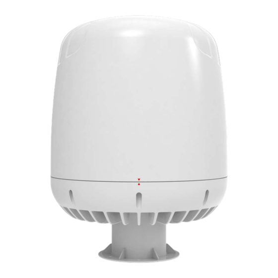
Step 1. Orienting the Antenna. Orientate the Antenna that the alignment notches are facing in your direction. Then inspect the fastening hole from angle below. See next image. Page 13 of 31 Poynting Group (Pty) Ltd Registration Number: 2014/239013/07 www.poynting.tech... -
Page 14: Step 2. Locating Dome Screws
M8 cap screw. The Cap screws are captive screws and only need to be Unscrewed till it drops lose into the cavity below. Continue to next step. Page 14 of 31 Poynting Group (Pty) Ltd Registration Number: 2014/239013/07 www.poynting.tech... -
Page 15: Step 4. Opening The Radome
Grab the Radome on the sides and lift it in an upwards direction till it stops moving. Please look at the image below and continue to next step Page 15 of 31 Poynting Group (Pty) Ltd Registration Number: 2014/239013/07 www.poynting.tech... -
Page 16: Step 5. Unscrewing The Gas Lifters
Step 5. Unscrewing the gas lifters. Unscrew all four M5 Cap screws that fastens gas lifters to base as shown in image below and continue to next step Page 16 of 31 Poynting Group (Pty) Ltd Registration Number: 2014/239013/07 www.poynting.tech... - Page 17 Main base is now open and ready for integration of electronic equipment. When done with Integration, please follow steps in reverse to assemble radome and to close unit. Page 17 of 31 Poynting Group (Pty) Ltd Registration Number: 2014/239013/07 www.poynting.tech...
-
Page 18: Fitting The Routers Inside The Antenna
Please study the following picture to decide where to place equipment and areas that are allowed to drill & tap holes and to witch recommended maximum depth. Space left blank intentionally Page 18 of 31 Poynting Group (Pty) Ltd Registration Number: 2014/239013/07 www.poynting.tech... -
Page 19: Connecting Antenna Rf Cables And Closing The Radome
Once the Router equipment has been installed in the base, hold the Radome on the sides and lower it onto the base in a downward movement until it lines up with the entry holes of the hydraulic lifters as shown below. Page 19 of 31 Poynting Group (Pty) Ltd Registration Number: 2014/239013/07 www.poynting.tech... -
Page 20: Step 2. Fasten All Four M5 Cap Screws
The purpose of the gas lifters is to keep the dome in the ‘open’ position in order to connect the Router RF connections as per Section 6.1 above. Page 20 of 31 Poynting Group (Pty) Ltd Registration Number: 2014/239013/07 www.poynting.tech... -
Page 21: Step 4: Connector Layout Inside The Antenna
Step 4: Connector layout inside the Antenna. Please study the following pictures to decide how to do cable management to routers installed. Antenna connections panel; larger image on following page Page 21 of 31 Poynting Group (Pty) Ltd Registration Number: 2014/239013/07 www.poynting.tech... - Page 22 Page 22 of 31 Poynting Group (Pty) Ltd Registration Number: 2014/239013/07 www.poynting.tech...
-
Page 23: Step 5. Closing The Radome
The Cap screws are captive screws and one only need to insert the 6mm Allen key and tighten each of the M8 screws to secure the dome. The dome should now be secured to the base and the WaveHunter ready to be installed. -
Page 24: Antenna Mounting Templates
7. Antenna Mounting Templates 7.1. Overview 7.2. Option 01 Mounting Option 01 with WaveHunter Base Holes Marked in Orange with Ø240 mm PCD Page 24 of 31 Poynting Group (Pty) Ltd Registration Number: 2014/239013/07 www.poynting.tech... - Page 25 7.3. Option 02 Mounting Option 02 with WaveHunter Base Holes Marked in Orange with Ø350 mm PCD. Intellian VSAT Mounting Spec Space left blank intentionally Page 25 of 31 Poynting Group (Pty) Ltd Registration Number: 2014/239013/07 www.poynting.tech...
-
Page 26: Mounting The Antenna
Marine Antenna deployment should be followed. 8.3. Following the recommendation to mount the WaveHunter as high as possible above the waterline, possibly on one of the Mast telecommunication equipment extensions, the Pedestal may not be required. -
Page 27: External Cables To The Wavehunter
IEC 60092-352 for specific guidance in choosing cables and installing cables onboard a ship. Within these guidelines, Poynting will provide some very general information regarding the electrical installation. In general, all cable shall be protected from chaffing and secured to a cableway. Cable runs on open deck or down a mast shall be in metal conduit suitable for marine use. -
Page 28: Grounding And Rf Protection
‘G-Shocks’, and it is therefore important to make sure that Router installation provides the necessary secure installation to the base of the WaveHunter to prevent these from detaching from the base and damaging the entire System. Poynting cannot be held liable for Antenna System damage due to poor securing of Router and/or Cables. -
Page 29: Rf Cable Check
11. After sale 11.1. Maintenance and Service. Poynting advises to perform an inspection, and the below mentioned maintenance steps, to the WaveHunter every six (6) months as from Commissioning. Customer shall report its findings to the system integrator immediately after the inspection in writing. Ideally, the system integrator/installer, should go on board the vessel every twelve (12) months to make a formal inspection him/herself. -
Page 30: Troubleshooting
Antenna. 11.3. Spare Parts. The following spare parts are shipped with the system: Spare part description Quantity M5 Bolts connecting the Gas-lifters to the WaveHunter base. ‘Captive Bolts’ securing the Radome to the WaveHunter base. Gas-lifters. Space left blank intentionally... - Page 31 Johannesburg A: Unit 4, N1 Industrial Park, Landmarks Ave, Samrand, 0157, South Africa P: PO Box 76579, Wendywood, 2144, South Africa T: +27 12 657 0050 | E: info@poynting.tech Space left blank intentionally Page 31 of 31 Poynting Group (Pty) Ltd Registration Number: 2014/239013/07 www.poynting.tech...
Need help?
Do you have a question about the Wavehunter and is the answer not in the manual?
Questions and answers